Downloaded 283 times


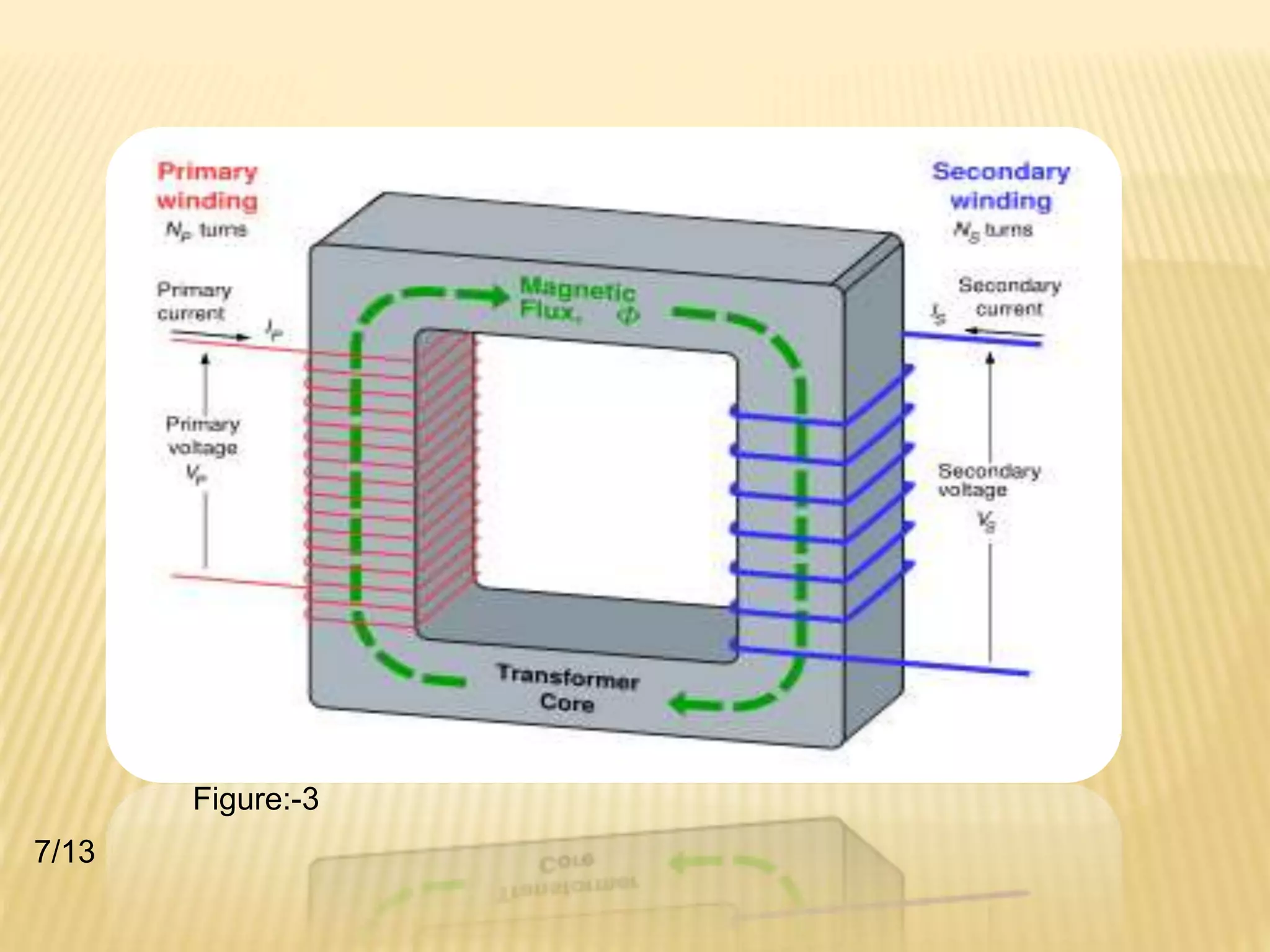

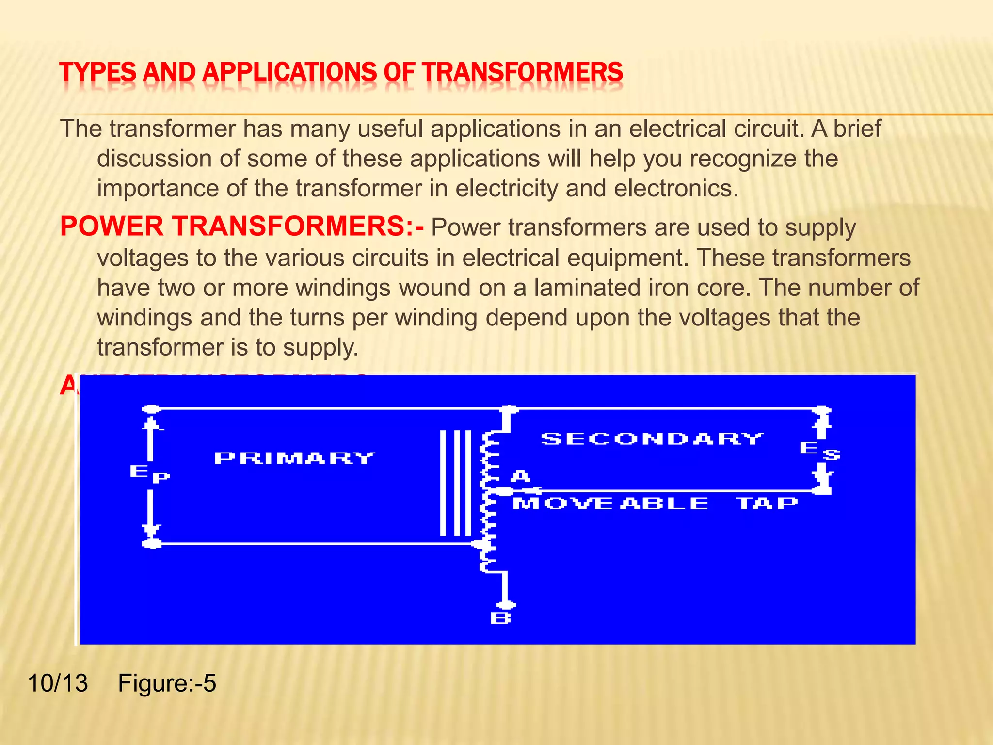


A transformer transfers electrical energy from one circuit to another through electromagnetic induction. It works by using two coils - a primary winding that receives energy from an alternating current source, and a secondary winding that delivers energy to a load. As the magnetic field in the primary coil fluctuates, it induces an alternating voltage in the secondary coil. This allows the transformer to increase or decrease voltage levels while keeping frequency constant. Common transformer types include power transformers used in electrical equipment and autotransformers with a single winding and movable tap to select different output voltages.


