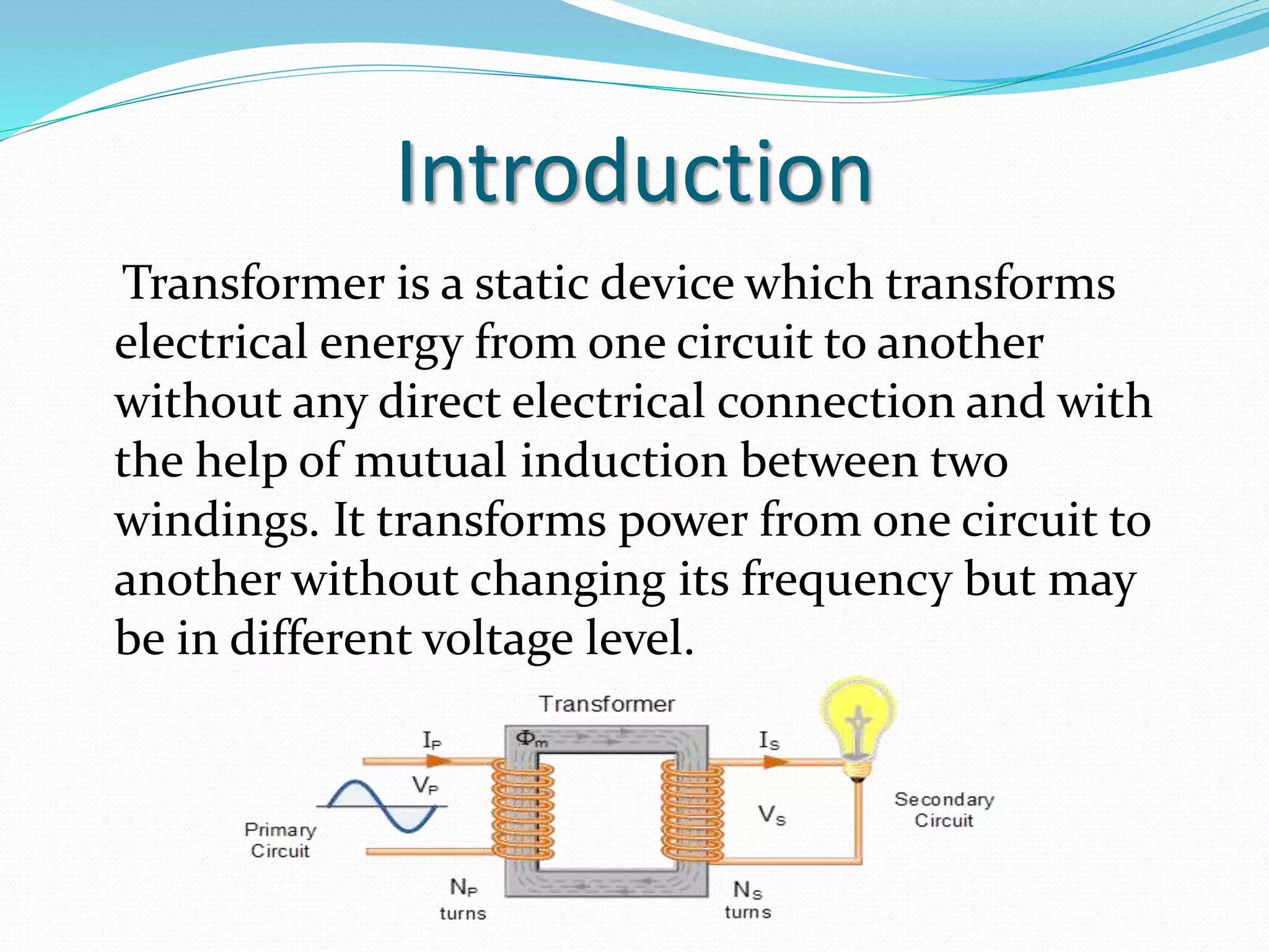
- Transformers transfer electrical energy from one circuit to another through mutual induction between two windings, and can change the voltage but not the frequency.
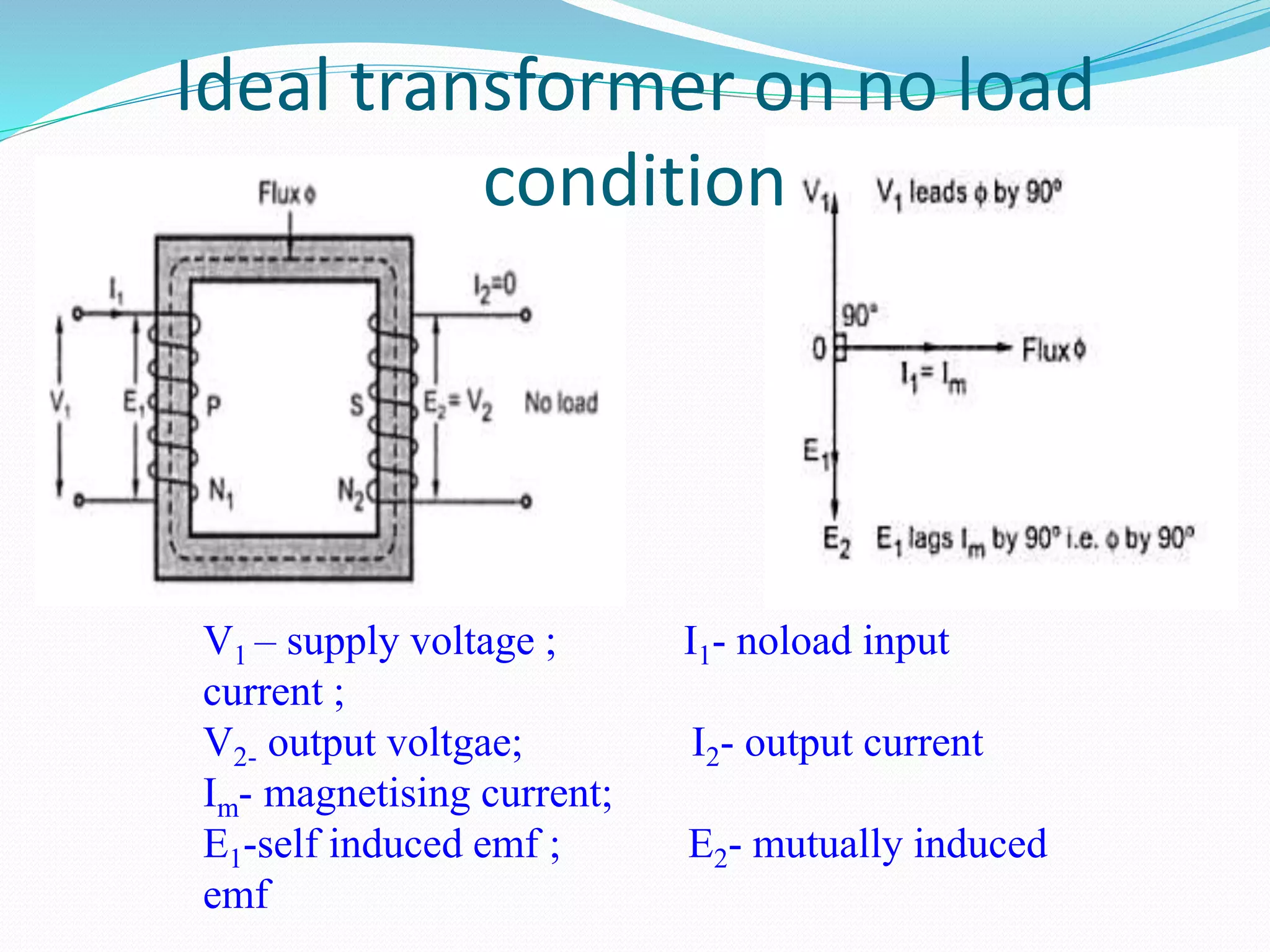
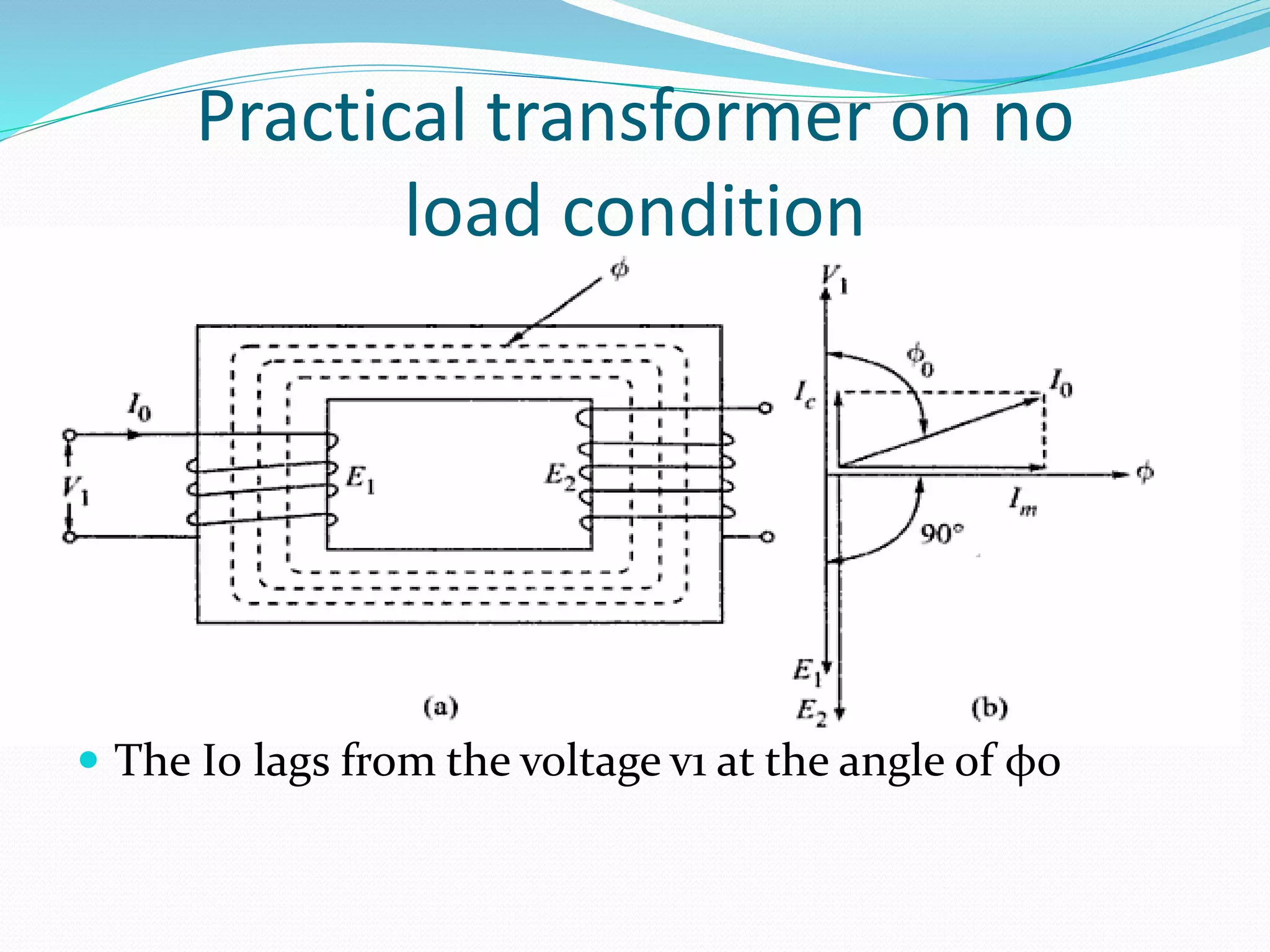
- They work on the principle of Faraday's law of induction, where a changing magnetic field in the primary coil induces an electromagnetic force (EMF) in the secondary coil.
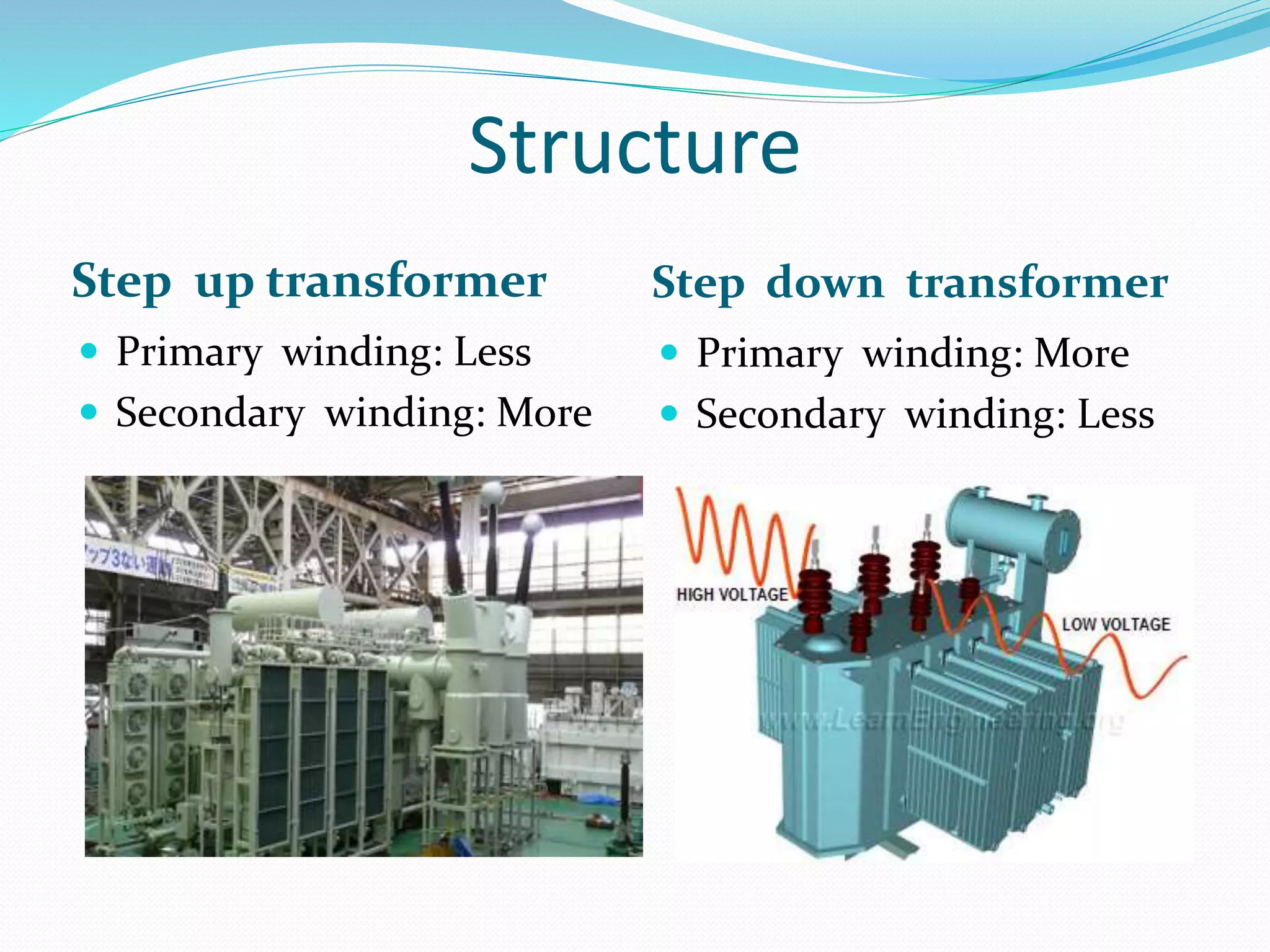
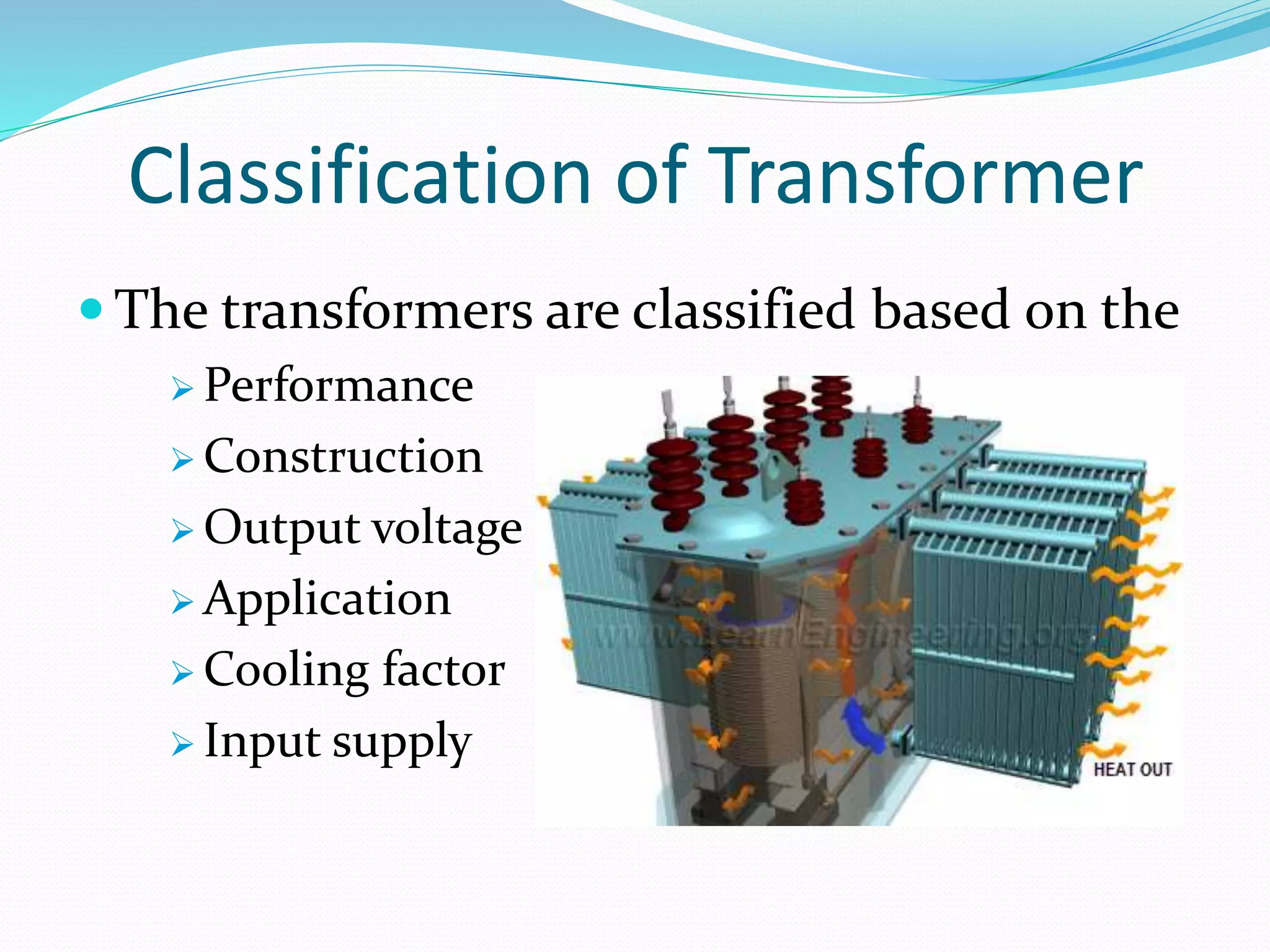
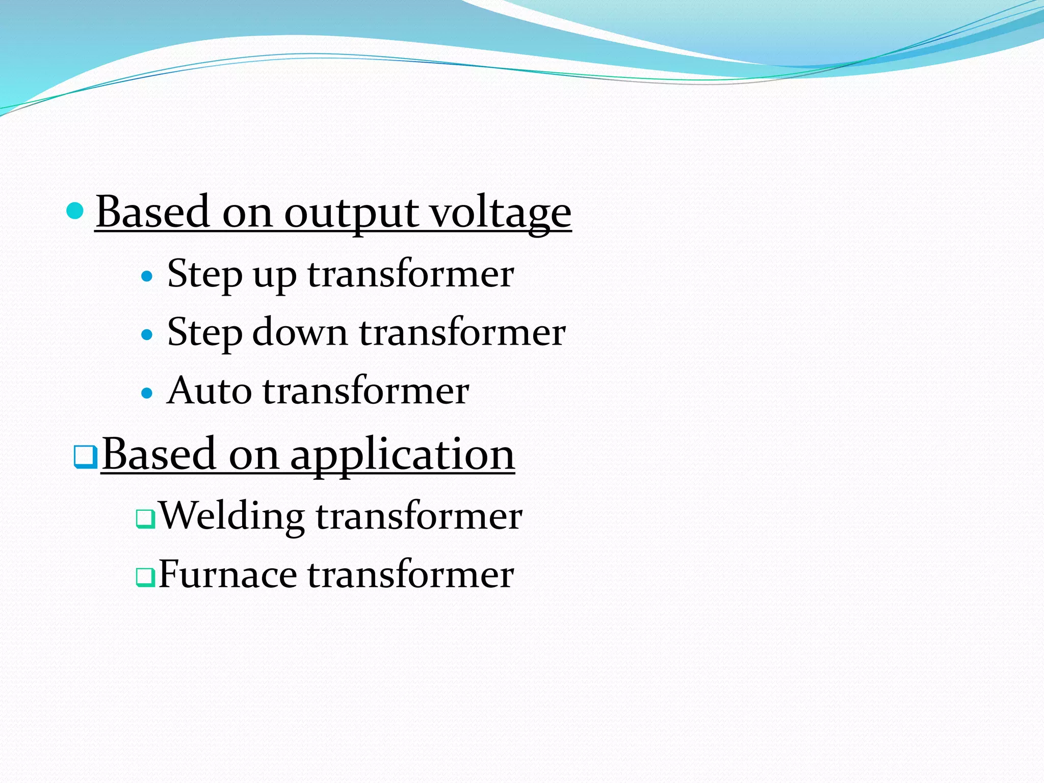
- Transformers are classified based on factors like performance, construction, voltages, applications, cooling, and input supply, and can be used to step up or step down voltages.