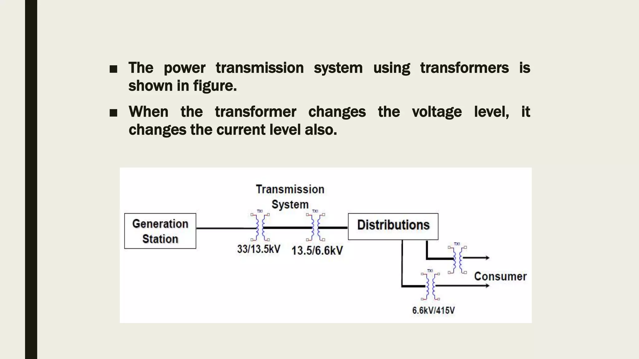
Persented by-vishal sahu
BPT=1semester
Jaipur national university
TRANSFORMER
Introduction
■ The transformer is a static device which is used to transfer electrical
energy from one ac circuit to another ac circuit.
■ Input to a transformer and output from a transformer both are
alternating quantities (AC).
■ Electrical energy is generated and transmitted at an extremely high
voltages. The voltage is to be then reduced to a lower value for its
domestic and industrial use.
■ This is done by using a transformer.
■ The power transmission system using transformers is
shown in figure.
■ When the transformer changes the voltage level, it
changes the current level also.
Basic Principle
■ The primary winding is connected to the single-phase ac
supply, an current starts flowing through it.
■ The ac primary current produces an alternating flux (Ф) in the core.
■ Most of this changing flux gets linked with the secondary winding
through the core.
■ The varying flux will induce voltage into the secondary
winding according to the faraday’s laws of electromagnetic
induction.
■ Voltage level change but frequency i.e. time period remains
same.
■ There is no electrical contact between the two winding, an
electrical energy gets transferred from primary to the
secondary.
■ A simple transformer consists of two electrical
conductors called the primary winding and the
secondary winding.
■ Energy is coupled between the windings by the
time varying magnetic flux that passes through(
links) both primary and secondary windings.
Construction
■ For the simple construction of a transformer, you must need two coils
having mutual inductance and a laminated steel core.
■ The two coils are insulated from each other and from the steel core.
■ The device will also need some suitable container for the assembled core
and windings, a medium with which the core and its windings from its
container can be insulated.
■ In order to insulate and to bring out the terminals of the winding
from the tank, apt bushings that are made from either porcelain or
capacitor type must be used.
■ In all transformers that are used commercially, the core is made out
of transformer sheet steel laminations assembled to provide a
continuous magnetic path with minimum of air-gap included.
■ The steel should have high permeability and low hysteresis
loss.
■ For this to happen, the steel should be made of high silicon
content and must also be heat treated.
■ By effectively laminating the core, the eddy-current losses
can be reduced.
■ The lamination can be done with the help of a light coat of
core plate varnish or lay an oxide layer on the surface.
■ For a frequency of 50 Hertz, the thickness of the
lamination varies from 0.35mm to 0.5mm for a frequency
of 25 Hertz.
Types of transformer
■ 2 types
• 1. Core- Type Transformer
• 2. Shell-Type Transformer
■ 1.Core-type Transformer
• the windings are given to a considerable part of the core.
• The coils used for this transformer are form-wound and are
of cylindrical type.
• The general arrangement of the core-type transformer
with respect to the core is shown below.
• Both low-voltage (LV) and high voltage (HV) windings
are shown.
• The low voltage windings are placed nearer to the core
as it is the asiest to insulate.
• The effective core area of the transformer can be
reduced with the use of laminations and insulation.
■ 2. Shell-Type Transformer
• In shell-type transformers, the core surrounds a considerable portion
of the . windings.
• The comparison is shown in the figure below.
• The coils are form-wound but are multi layer disc type usually wound
in the form of pancakes.
• Paper is used to insulate the different layers of the multi-layer discs.
• The whole winding consists of discs stacked with insulation spaces
between the coils.
■ Applications of a transformer
■ Transformers are used in most electronic circuits. A transformer
has only 3 applications;
■ To step up voltage and current.
■ To Step down voltage and current
■ To prevent DC – transformers can pass only Alternating
Currents so they totally prevent DC from passing to the next
circuit.
Uses of transformer
■ The most important uses and application of Transformer are:
■ It can rise or lower the level of level of Voltage or Current
( when voltage increases, current decreases and vice virsa
because P =V x I, and Power is same ) in an AC Circuit.
■ It can increase or decrease the value of capacitor, an inductor
or resistance in an AC circuit. It can thus act as an impedance
transferring device.
■ It can be used to prevent DC from passing from one circuit
to the other.
■ it can isolate two circuits electrically.
Article....
Faradic current
■ ABSTRACT
■ Here we report a facile approach to synthesize a novel nanostructured
thin film comprising Cu nanoparticles (NPs) and reduced graphene
oxide (rGO) on a glassy carbon electrode (GCE) via the direct
electrochemical reduction of a mixture of cupper and graphene oxide
(GO) precursors.
■ The effect of the applied potential on the electrochemical reduction of
CO2 was investigated using linear sweep voltammetric (LSV) and
chronoampero- metric (CA) techniques.
■ Carbon monoxide and formate were found as the main products based
on our GC and HPLC analysis.
Results and discussion
■ As seen from the FE-SEM images, a graphene-like thin film was
formed following the electrochemical reduction of graphene oxide
(Fig. 1a), while a crystal-like cluster structure of Cu NPs appeared
subsequent to the electrochemical reduction of the CuSO4
precursor (Fig. 1b).
■ The simultaneous formation of the Cu/rGO thin film was achieved
following the electrochemical reduction of the mixed GO and CuSO4
precursor (Fig. 1c), where Cu NPs with ~20 nm were uniformly
distributed on the rGO sheets.
Conclusions
■ A novel nanostructured Cu/rGO thin film was directly formed on the
GCE surface via a facile one-step electrochemical reduction of their
precursor mixture.
■ The SEM images showed that Cu nanoparticles were uniformly
distributed on the rGO nanosheets.
■ LSV and CA were em-ployed to study the effect of the applied
potential on the electro-chemical reduction of CO2 and to determine
the instant and the steady- state current efficiency of the Cu/rGO
thin film, demonstrating that the Cu/rGO thin film was highly
efficient for CO2 reduction.
Transformer  bpt students in physiotherapy

Transformer bpt students in physiotherapy

  • 1.
    Persented by-vishal sahu BPT=1semester Jaipurnational university TRANSFORMER
  • 2.
    Introduction ■ The transformeris a static device which is used to transfer electrical energy from one ac circuit to another ac circuit. ■ Input to a transformer and output from a transformer both are alternating quantities (AC). ■ Electrical energy is generated and transmitted at an extremely high voltages. The voltage is to be then reduced to a lower value for its domestic and industrial use. ■ This is done by using a transformer.
  • 3.
    ■ The powertransmission system using transformers is shown in figure. ■ When the transformer changes the voltage level, it changes the current level also.
  • 4.
  • 5.
    ■ The primarywinding is connected to the single-phase ac supply, an current starts flowing through it. ■ The ac primary current produces an alternating flux (Ф) in the core. ■ Most of this changing flux gets linked with the secondary winding through the core.
  • 6.
    ■ The varyingflux will induce voltage into the secondary winding according to the faraday’s laws of electromagnetic induction. ■ Voltage level change but frequency i.e. time period remains same. ■ There is no electrical contact between the two winding, an electrical energy gets transferred from primary to the secondary.
  • 7.
    ■ A simpletransformer consists of two electrical conductors called the primary winding and the secondary winding. ■ Energy is coupled between the windings by the time varying magnetic flux that passes through( links) both primary and secondary windings.
  • 8.
    Construction ■ For thesimple construction of a transformer, you must need two coils having mutual inductance and a laminated steel core. ■ The two coils are insulated from each other and from the steel core. ■ The device will also need some suitable container for the assembled core and windings, a medium with which the core and its windings from its container can be insulated.
  • 9.
    ■ In orderto insulate and to bring out the terminals of the winding from the tank, apt bushings that are made from either porcelain or capacitor type must be used. ■ In all transformers that are used commercially, the core is made out of transformer sheet steel laminations assembled to provide a continuous magnetic path with minimum of air-gap included.
  • 10.
    ■ The steelshould have high permeability and low hysteresis loss. ■ For this to happen, the steel should be made of high silicon content and must also be heat treated. ■ By effectively laminating the core, the eddy-current losses can be reduced.
  • 11.
    ■ The laminationcan be done with the help of a light coat of core plate varnish or lay an oxide layer on the surface. ■ For a frequency of 50 Hertz, the thickness of the lamination varies from 0.35mm to 0.5mm for a frequency of 25 Hertz.
  • 12.
    Types of transformer ■2 types • 1. Core- Type Transformer • 2. Shell-Type Transformer ■ 1.Core-type Transformer • the windings are given to a considerable part of the core. • The coils used for this transformer are form-wound and are of cylindrical type.
  • 13.
    • The generalarrangement of the core-type transformer with respect to the core is shown below. • Both low-voltage (LV) and high voltage (HV) windings are shown. • The low voltage windings are placed nearer to the core as it is the asiest to insulate. • The effective core area of the transformer can be reduced with the use of laminations and insulation.
  • 14.
    ■ 2. Shell-TypeTransformer • In shell-type transformers, the core surrounds a considerable portion of the . windings. • The comparison is shown in the figure below. • The coils are form-wound but are multi layer disc type usually wound in the form of pancakes. • Paper is used to insulate the different layers of the multi-layer discs. • The whole winding consists of discs stacked with insulation spaces between the coils.
  • 15.
    ■ Applications ofa transformer ■ Transformers are used in most electronic circuits. A transformer has only 3 applications; ■ To step up voltage and current. ■ To Step down voltage and current ■ To prevent DC – transformers can pass only Alternating Currents so they totally prevent DC from passing to the next circuit.
  • 16.
  • 17.
    ■ The mostimportant uses and application of Transformer are: ■ It can rise or lower the level of level of Voltage or Current ( when voltage increases, current decreases and vice virsa because P =V x I, and Power is same ) in an AC Circuit. ■ It can increase or decrease the value of capacitor, an inductor or resistance in an AC circuit. It can thus act as an impedance transferring device. ■ It can be used to prevent DC from passing from one circuit to the other. ■ it can isolate two circuits electrically.
  • 18.
    Article.... Faradic current ■ ABSTRACT ■Here we report a facile approach to synthesize a novel nanostructured thin film comprising Cu nanoparticles (NPs) and reduced graphene oxide (rGO) on a glassy carbon electrode (GCE) via the direct electrochemical reduction of a mixture of cupper and graphene oxide (GO) precursors. ■ The effect of the applied potential on the electrochemical reduction of CO2 was investigated using linear sweep voltammetric (LSV) and chronoampero- metric (CA) techniques. ■ Carbon monoxide and formate were found as the main products based on our GC and HPLC analysis.
  • 19.
    Results and discussion ■As seen from the FE-SEM images, a graphene-like thin film was formed following the electrochemical reduction of graphene oxide (Fig. 1a), while a crystal-like cluster structure of Cu NPs appeared subsequent to the electrochemical reduction of the CuSO4 precursor (Fig. 1b). ■ The simultaneous formation of the Cu/rGO thin film was achieved following the electrochemical reduction of the mixed GO and CuSO4 precursor (Fig. 1c), where Cu NPs with ~20 nm were uniformly distributed on the rGO sheets.
  • 20.
    Conclusions ■ A novelnanostructured Cu/rGO thin film was directly formed on the GCE surface via a facile one-step electrochemical reduction of their precursor mixture. ■ The SEM images showed that Cu nanoparticles were uniformly distributed on the rGO nanosheets. ■ LSV and CA were em-ployed to study the effect of the applied potential on the electro-chemical reduction of CO2 and to determine the instant and the steady- state current efficiency of the Cu/rGO thin film, demonstrating that the Cu/rGO thin film was highly efficient for CO2 reduction.