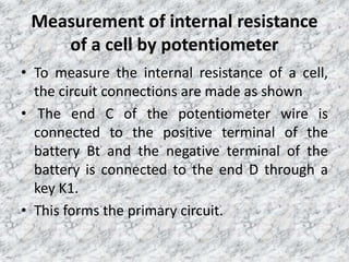
Downloaded 325 times

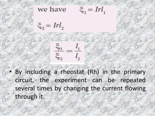
![• The DPDT switch is pressed towards M1, N1 so
that cell ξ1 is included in the secondary circuit
and the balancing length l1 is found by
adjusting the jockey for zero deflection.
• Then the second cell ξ2 is included in the circuit
and the balancing length l2 is determined.
• Let r be the resistance per unit length of the
potentiometer wire and I be the current
flowing through the wire ]k](https://image.slidesharecdn.com/7-potentiometer-191008051115/85/POTENTIOMETER-9-320.jpg)
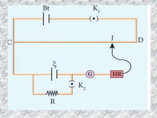


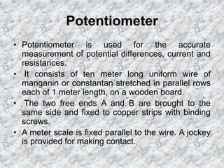
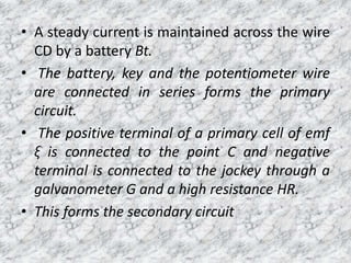
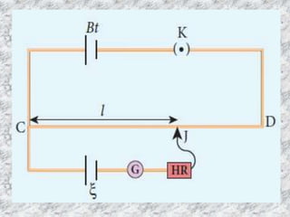
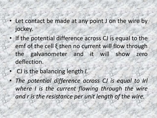
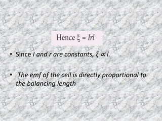
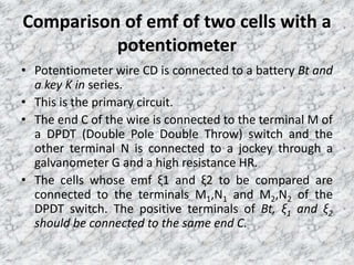
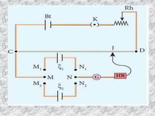
The potentiometer is used to accurately measure potential differences, currents, and resistances. It consists of a long uniform wire stretched parallel on a board, with terminals at both ends connected to copper strips. A battery maintains a current through the wire, forming the primary circuit. A cell's terminals connect to points on the wire in a secondary circuit including a galvanometer. The balancing length where no current flows through the galvanometer is directly proportional to the cell's electromotive force. A potentiometer can also compare emf values of two cells and determine a cell's internal resistance by varying an external resistor connected across it.


![potentiometer presentation slide [Autosaved].pptx](https://cdn.slidesharecdn.com/ss_thumbnails/potentiometerpresentationslideautosaved-240204142748-a5b488e5-thumbnail.jpg?width=640&height=640&fit=bounds)


![ppt current electricity -2developed [Autosaved] (1).pptx](https://cdn.slidesharecdn.com/ss_thumbnails/pptcurrentelectricity-2developedautosaved1-250724095217-f3899f3e-thumbnail.jpg?width=640&height=640&fit=bounds)


