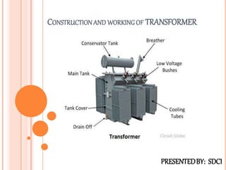
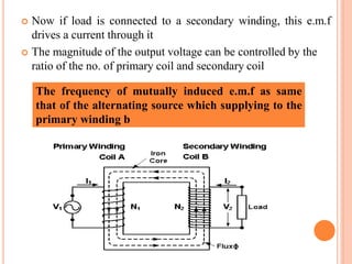
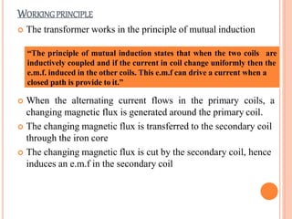
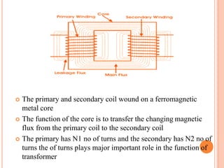
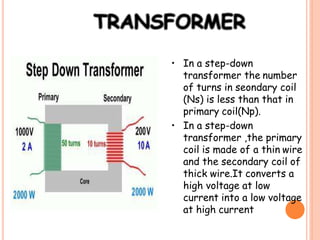
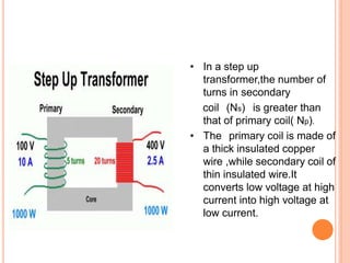
2. CONTENT
What is transformer
Structure and working principle
Construction of transformer
Classification of transformer
Losses in transformer
Uses and application of transformer
3. WHAT IS TRANSFORMER
A transformer is a static piece of apparatus by means of
which an electrical power is transferred from one
alternating current circuit to another electrical circuit
There is no electrical contact between them
The desire change in voltage or current without any
change in frequency
Symbolically the transformer denoted as
NOTE :
Itworkson theprincipleof mutualinduction
4. STRUCTURE OF TRANSFORMER
The transformer two inductive coils ,these are electrical
separated but linked through a common magnetic current
circuit
These two coils have a high mutual induction
One of the two coils is connected of alternating voltage .this
coil in which electrical energy is fed with the help of source
called primary winding (P) shown in fig.
The other winding is connected to a load the electrical energy
is transformed to this winding drawn out to the load .this
winding is called secondary winding(S) shown in fig.
5. Now if load is connected to a secondary winding, this e.m.f
drives a current through it
The magnitude of the output voltage can be controlled by the
ratio of the no. of primary coil and secondary coil
The frequency of mutually induced e.m.f as same
that of the alternating source which supplying to the
primary winding b
6. WORKINGPRINCIPLE
The transformer works in the principle of mutual induction
“The principle of mutual induction states that when the two coils are
inductively coupled and if the current in coil change uniformly then the
e.m.f. induced in the other coils. This e.m.f can drive a current when a
closed path is provide to it.”
When the alternating current flows in the primary coils, a
changing magnetic flux is generated around the primary coil.
The changing magnetic flux is transferred to the secondary coil
through the iron core
The changing magnetic flux is cut by the secondary coil, hence
induces an e.m.f in the secondary coil
7. The primary and secondary coil wound on a ferromagnetic
metal core
The function of the core is to transfer the changing magnetic
flux from the primary coil to the secondary coil
The primary has N1 no of turns and the secondary has N2 no of
turns the of turns plays major important role in the function of
transformer
8. • In a step-down
transformer the number
of turns in seondary coil
(Ns) is less than that in
primary coil(Np).
• In a step-down
transformer ,the primary
coil is made of a thin wire
and the secondary coil of
thick wire.It converts a
high voltage at low
current into a low voltage
at high current
9. • In a step up
transformer,the number of
turns in secondary
coil (Ns) is greater than
that of primary coil( Np).
• The primary coil is made of
a thick insulated copper
wire ,while secondary coil of
thin insulated wire.It
converts low voltage at high
current into high voltage at
low current.
13. Three phase transformer
Normally , when three-phase is required, a single enclosure with three
primary and three secondary windings wound on a common core is all that
is required. However three single-phase transformers with the same rating
can be connected to form a three-phase bank. Since each single-phase
transformer has a primary and a secondary winding, then 3 single-phase
transformers will have the required 3 primary and 3 secondary windings
and can be connected in the field either Delta-Delta or Delta-Wye to
achieve the required three-phased transformer bank
14. CORE TYPE CONSTRUCTION
In this one magnetic circuit and cylindrical coils are used
Normally L and T shaped laminations areused
Commonly primary winding would on one limb while
secondary on the other but performance will be reduce
To get high performance it is necessary that other the two
winding should be very close to each other
15.
16. SHELL TYPE CONSTRUCTION
In this type two magnetic circuit are used
The winding is wound on central limbs
For the cell type each high voltage winding lie between two
voltage portion sandwiching the high voltage winding
Sub division of windings reduces the leakage flux
Greater the number of sub division lesser the reactance
This type of construction is used for high voltage
17.
18. LOSSES IN TRANSFORMER
Copper losses :
It is due to power wasted in the form of I2Rdue to
resistance of primary and secondary. The magnitude of
copper losses depend upon the current flowing through
these coils.
The iron losses depend on the supply voltage while the copper depend
on the current .the losses are not dependent on the phase angle between
current and voltage .hence the rating of the transformer is expressed as
a product o f voltage and current called VArating of transformer. It is
not expressed in watts or kilowatts. Most of the timer, is rating is
expressed in KVA.
19. Hysteresis loss :
During magnetization and demagnetization ,due to hysteresis
effect some energy losses in the core called hysteresis loss
Eddy current loss :
The leakage magnetic flux generates the E.M.F in the core
produces current is called of eddy current loss.
20. APPLICATIONS
• A step-down transformer
is used for obtaining large
current for electric
welding.
• A step-down transformer
is used in induction
furnace for melting the
metals.
• A step-up transformer is
used for the production of
X-rays.
• Transformers are used in
voltage regulators and
stabilised power supplies.