Download to read offline
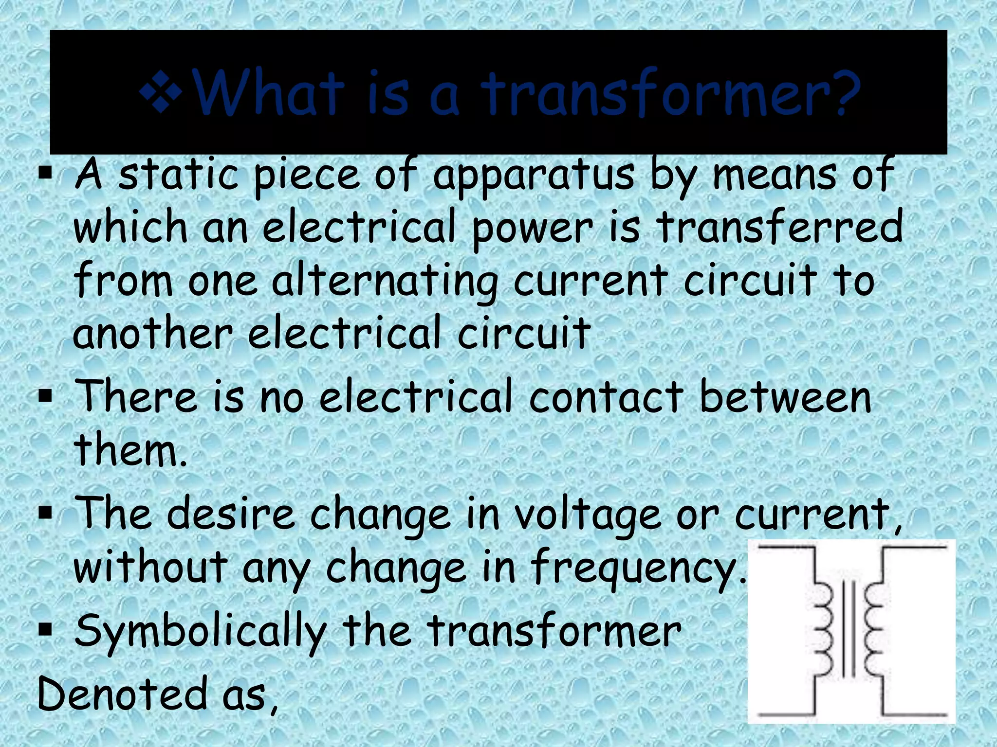
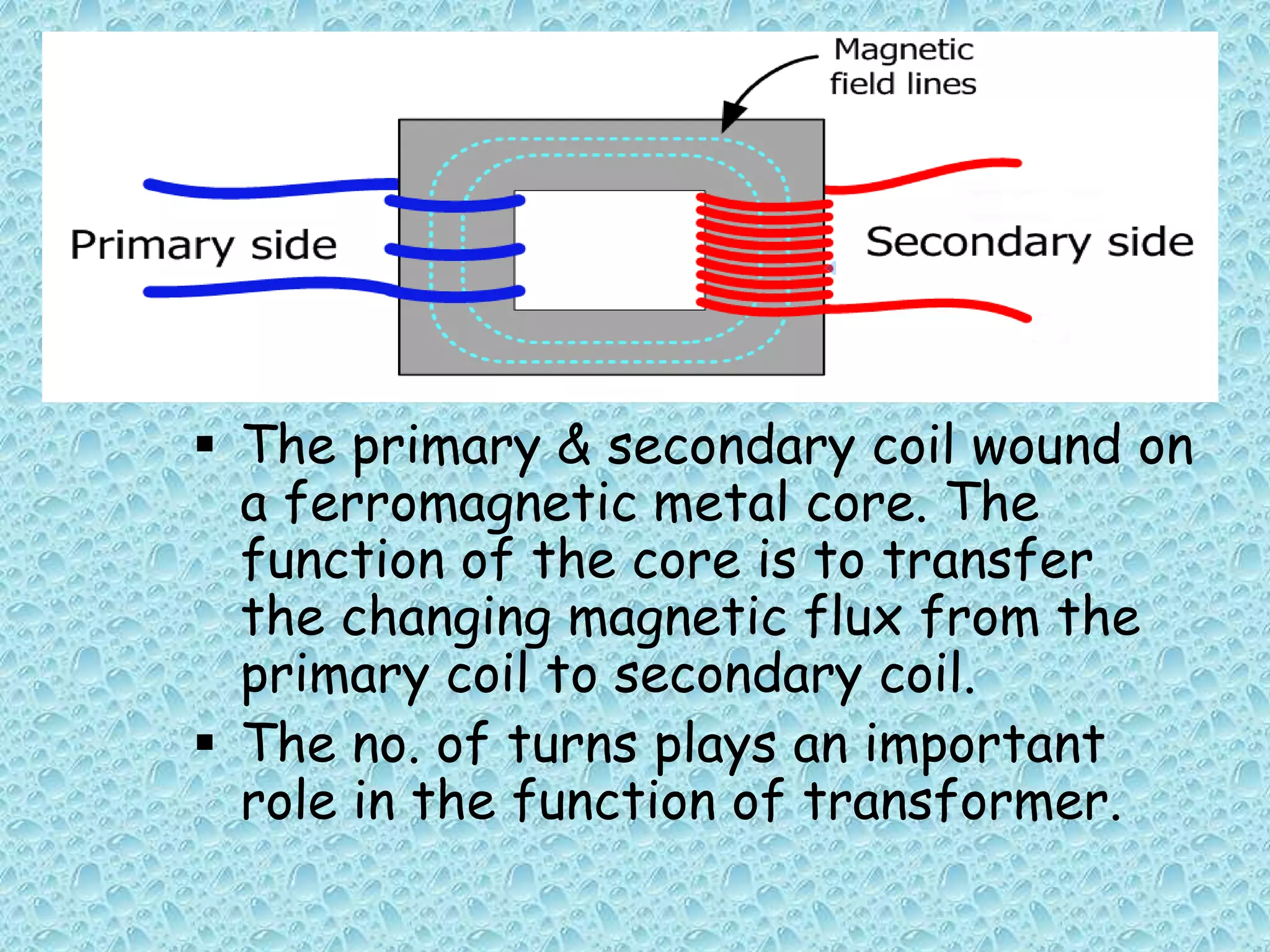
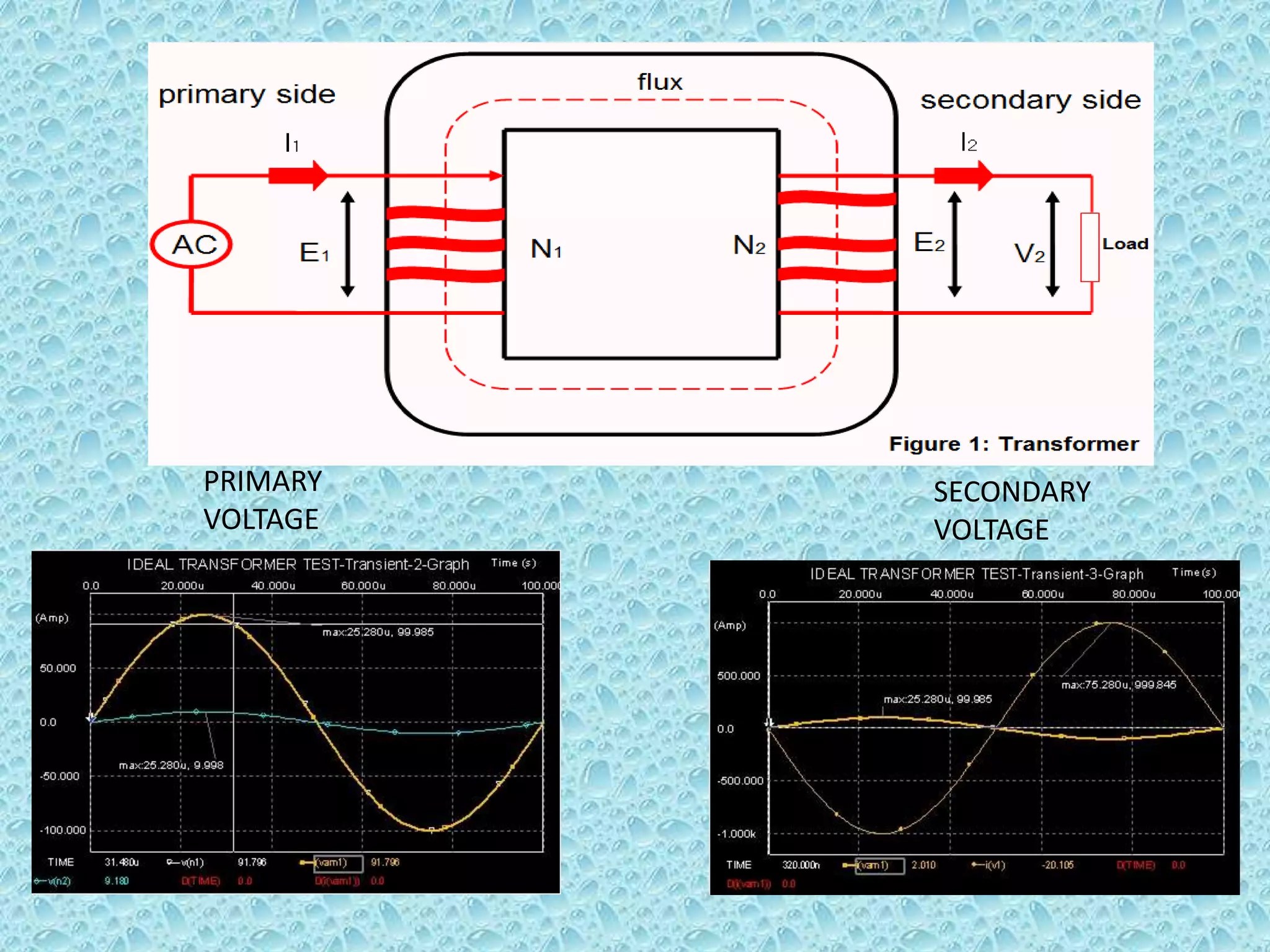


This document provides an overview of transformers. It begins by defining a transformer as a static device that transfers electrical power between two alternating current circuits without a direct electrical connection. The key parts of a transformer are then described, including the primary and secondary coils wound around a ferromagnetic core. The document explains that a transformer works on the principle of mutual induction to step up or step down voltages. Various types of transformer constructions and applications are also summarized, along with sources of transformer losses and limitations compared to an ideal transformer.


