This document provides an overview of transformers, including:
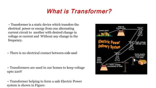
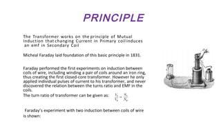
- Transformers transfer electrical power from one alternating current circuit to another with a change in voltage or current, but no change in frequency. They work on the principle of mutual induction.
- The history of transformers dates back to experiments by Faraday and Henry in the 1830s, with the first widely used type being the induction coil invented in 1836.
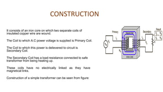
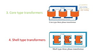
- A transformer consists of two coils - a primary and secondary coil - wound around an iron core. It works by inducing an EMF in the secondary coil via a changing magnetic flux from the primary coil.
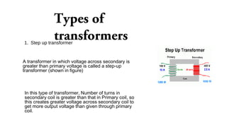
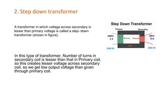
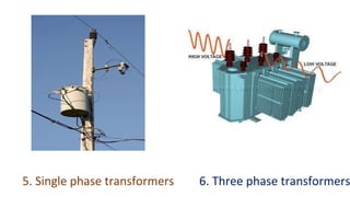
- Transformers can be used to step up or step down voltages and are critical components in