The document provides information about transformers, including:
1. It describes the basic working principle of a transformer, which operates on mutual induction between two inductively coupled coils.
2. It classifies transformers based on their duty, construction, voltage output, application, cooling method, and input supply.
3. It discusses the constructional details of transformers including their cores, windings, and magnetic circuits.
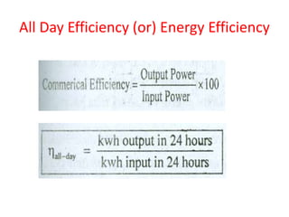
4. It covers transformer testing methods like open circuit, short circuit, and load tests used to determine losses, efficiency, and other parameters.