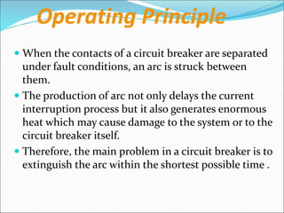
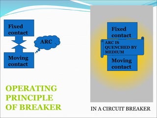
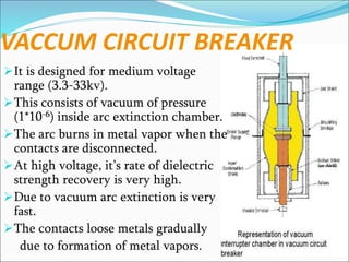
Circuit breakers are switching devices that can make, carry, and break electric currents under both normal and abnormal circuit conditions. They contain fixed and moving contacts that remain closed during normal operation but open automatically during faults to interrupt the fault current. When contacts open under fault conditions, an arc is produced that must be quickly extinguished. Different circuit breakers use various mediums like oil, air, vacuum, or SF6 gas to rapidly quench the arc through cooling and increasing dielectric strength between contacts. Common types of circuit breakers include oil, vacuum, air blast, and SF6 breakers that vary based on voltage level, switching speed, maintenance needs, and arc quenching method.
How is power transformer protected??? This provides a basic understanding of power transformer. Furthermore, the protective relay application on power transformer is included.
Unit I: Introduction to Protection System:
Introduction to protection system and its elements, functions of protective relaying, protective zones, primary and backup protection, desirable qualities of protective relaying, basic terminology.
Relays:
Electromagnetic, attracted and induction type relays, thermal relay, gas actuated relay, design considerations of electromagnetic relay.
Unit-II: Relay Application and Characteristics:
Amplitude and phase comparators, over current relays, directional relays, distance relays, differential relay.
Static Relays: Comparison with electromagnetic relay, classification and their description, over current relays, directional relay, distance relays, differential relay.
Unit-III Protection of Transmission Line:
Over current protection, distance protection, pilot wire protection, carrier current protection, protection of bus, auto re-closing,
Unit-IV: Circuit Breaking:
Properties of arc, arc extinction theories, re-striking voltage transient, current chopping, resistance switching, capacitive current interruption, short line interruption, circuit breaker ratings.
Testing Of Circuit Breaker: Classification, testing station and equipments, testing procedure, direct and indirect testing.
Unit-V Apparatus Protection:
Protection of Transformer, generator and motor.
Circuit Breaker: Operating modes, selection of circuit breakers, constructional features and operation of Bulk Oil, Minimum Oil, Air Blast, SF6, Vacuum and d. c. circuit breakers.
A switchgear or electrical switchgear is a generic term which includes all the switching devices associated with mainly power system protection. It also includes all devices associated with control, metering and regulating of electrical power system. Assembly of such devices in a logical manner forms a switchgear. This is the very basic definition of switchgear.
⋗To get more with details
https://www.youtube.com/channel/UC2SvKI7eepP241VLoui1D5A
It describes about the circuit breaker and components and types of high voltage circuit breaker. It also explains about the working principle of the circuit breaker.
AC Distribution in Bangladesh (in a nutshell)Ridwanul Hoque
Power System is an integrated network that interconnects the installations for generation, transmission and distribution of electricity. In Bangladesh electricity is generated at 50 Hertz frequency and at a nominal voltage of 11 KV (Kilo Volts) or 15 KV to be stepped up through transformers to 132 kV or 230 kV for feeding to the grid i.e. a high voltage transmission network that transmits the power to grid substation transformers to be stepped down at 33 kV. 11 kV and 0.4 kV for delivery to the consumers of various categories.
In electronics, impedance matching is the practice of designing the input impedance of an electrical load or the output impedance of its corresponding signal source to maximize the power transfer or minimize signal reflection from the load.
Loadability of line is defined as the extent of load which can flow through the line without exceeding the limitations. Line Loadability is expressed in percentage of Surge Impedance Loading of line. The limiting factor for line loading are: thermal limit, voltage drop limit and steady state stability.
Equipment and Stability Constraints : System OperationRidwanul Hoque
There are two types of constraints which limit the capability of a power system: If the overloading exceeds limits, the equipment is tripped out by protection systems. b) Stability Constraints: A power system may not be able to cater to power flows beyond a certain point due to stability constraints.
A power system control is required to maintain a continuous balance between power generation and load demand. Load Frequency Controller and Automatic Voltage Regulator play an important role in maintaining constant frequency and voltage in order to ensure the reliability of electric power.
HVDC stands for high voltage direct current, a well-proven technology used to transmit electricity over long distances by overhead transmission lines or submarine cables. It is also used to interconnect separate power systems, where traditional alternating current (AC) connections cannot be used.
Hydro Power Plants capture the energy of falling water to generate electricity. A turbine converts the kinetic energy of falling water into mechanical energy. Then a generator converts the mechanical energy from the turbine into electrical energy.
There are three main types of conventional hydropower technologies: impoundment (dam), diversion, and pumped storage. Impoundment is the most common type of hydroelectric power plant. An impoundment facility, typically a large hydro-power system, uses a dam to store river water in a reservoir.
The Rankine cycle or Rankine Vapor Cycle is the process widely used by power plants such as coal-fired power plants or nuclear reactors. In this mechanism, a fuel is used to produce heat within a boiler, converting water into steam which then expands through a turbine producing useful work.
The steam-electric power station is a power station in which the electric generator is steam driven.
The Rankine cycle or Rankine Vapor Cycle is the process widely used by power plants such as coal-fired power plants or nuclear reactors. In this mechanism, a fuel is used to produce heat within a boiler, converting water into steam which then expands through a turbine producing useful work.
The aim of our presentation is to describe the AC Distribution system in Bangladesh.
Following are the focused points in terms of Bangladesh perspective:
1. Distribution Procedure
2. Primary and Secondary Distribution System
3. Distribution Substation
4. Distribution Companies
5. Distribution in both City and Rural Area
6. Distribution Loss
7. Protective Devices
8. User Variety
8. Billing Procedure
Power system stability is the ability of an electric power system, for a given initial operating condition, to regain a state of operating equilibrium after being subjected to a physical disturbance, with most system variables bounded so that practically the entire system remains intact.
Economic operation of power system. (i) One dealing with minimum cost of power production called Economic dispatch. (ii) Other dealing with minimum loss of the generated power delivery to the loads. For any specified load condition, economic dispatch (i) determines the power output of each plant.
TECHNICAL TRAINING MANUAL GENERAL FAMILIARIZATION COURSEDuvanRamosGarzon1
AIRCRAFT GENERAL
The Single Aisle is the most advanced family aircraft in service today, with fly-by-wire flight controls.
The A318, A319, A320 and A321 are twin-engine subsonic medium range aircraft.
The family offers a choice of engines
Democratizing Fuzzing at Scale by Abhishek Aryaabh.arya
Presented at NUS: Fuzzing and Software Security Summer School 2024
This keynote talks about the democratization of fuzzing at scale, highlighting the collaboration between open source communities, academia, and industry to advance the field of fuzzing. It delves into the history of fuzzing, the development of scalable fuzzing platforms, and the empowerment of community-driven research. The talk will further discuss recent advancements leveraging AI/ML and offer insights into the future evolution of the fuzzing landscape.
Saudi Arabia stands as a titan in the global energy landscape, renowned for its abundant oil and gas resources. It's the largest exporter of petroleum and holds some of the world's most significant reserves. Let's delve into the top 10 oil and gas projects shaping Saudi Arabia's energy future in 2024.
Sachpazis:Terzaghi Bearing Capacity Estimation in simple terms with Calculati...Dr.Costas Sachpazis
Terzaghi's soil bearing capacity theory, developed by Karl Terzaghi, is a fundamental principle in geotechnical engineering used to determine the bearing capacity of shallow foundations. This theory provides a method to calculate the ultimate bearing capacity of soil, which is the maximum load per unit area that the soil can support without undergoing shear failure. The Calculation HTML Code included.
About
Indigenized remote control interface card suitable for MAFI system CCR equipment. Compatible for IDM8000 CCR. Backplane mounted serial and TCP/Ethernet communication module for CCR remote access. IDM 8000 CCR remote control on serial and TCP protocol.
• Remote control: Parallel or serial interface.
• Compatible with MAFI CCR system.
• Compatible with IDM8000 CCR.
• Compatible with Backplane mount serial communication.
• Compatible with commercial and Defence aviation CCR system.
• Remote control system for accessing CCR and allied system over serial or TCP.
• Indigenized local Support/presence in India.
• Easy in configuration using DIP switches.
Technical Specifications
Indigenized remote control interface card suitable for MAFI system CCR equipment. Compatible for IDM8000 CCR. Backplane mounted serial and TCP/Ethernet communication module for CCR remote access. IDM 8000 CCR remote control on serial and TCP protocol.
Key Features
Indigenized remote control interface card suitable for MAFI system CCR equipment. Compatible for IDM8000 CCR. Backplane mounted serial and TCP/Ethernet communication module for CCR remote access. IDM 8000 CCR remote control on serial and TCP protocol.
• Remote control: Parallel or serial interface
• Compatible with MAFI CCR system
• Copatiable with IDM8000 CCR
• Compatible with Backplane mount serial communication.
• Compatible with commercial and Defence aviation CCR system.
• Remote control system for accessing CCR and allied system over serial or TCP.
• Indigenized local Support/presence in India.
Application
• Remote control: Parallel or serial interface.
• Compatible with MAFI CCR system.
• Compatible with IDM8000 CCR.
• Compatible with Backplane mount serial communication.
• Compatible with commercial and Defence aviation CCR system.
• Remote control system for accessing CCR and allied system over serial or TCP.
• Indigenized local Support/presence in India.
• Easy in configuration using DIP switches.
Quality defects in TMT Bars, Possible causes and Potential Solutions.PrashantGoswami42
Maintaining high-quality standards in the production of TMT bars is crucial for ensuring structural integrity in construction. Addressing common defects through careful monitoring, standardized processes, and advanced technology can significantly improve the quality of TMT bars. Continuous training and adherence to quality control measures will also play a pivotal role in minimizing these defects.
Water scarcity is the lack of fresh water resources to meet the standard water demand. There are two type of water scarcity. One is physical. The other is economic water scarcity.
Welcome to WIPAC Monthly the magazine brought to you by the LinkedIn Group Water Industry Process Automation & Control.
In this month's edition, along with this month's industry news to celebrate the 13 years since the group was created we have articles including
A case study of the used of Advanced Process Control at the Wastewater Treatment works at Lleida in Spain
A look back on an article on smart wastewater networks in order to see how the industry has measured up in the interim around the adoption of Digital Transformation in the Water Industry.
COLLEGE BUS MANAGEMENT SYSTEM PROJECT REPORT.pdfKamal Acharya
The College Bus Management system is completely developed by Visual Basic .NET Version. The application is connect with most secured database language MS SQL Server. The application is develop by using best combination of front-end and back-end languages. The application is totally design like flat user interface. This flat user interface is more attractive user interface in 2017. The application is gives more important to the system functionality. The application is to manage the student’s details, driver’s details, bus details, bus route details, bus fees details and more. The application has only one unit for admin. The admin can manage the entire application. The admin can login into the application by using username and password of the admin. The application is develop for big and small colleges. It is more user friendly for non-computer person. Even they can easily learn how to manage the application within hours. The application is more secure by the admin. The system will give an effective output for the VB.Net and SQL Server given as input to the system. The compiled java program given as input to the system, after scanning the program will generate different reports. The application generates the report for users. The admin can view and download the report of the data. The application deliver the excel format reports. Because, excel formatted reports is very easy to understand the income and expense of the college bus. This application is mainly develop for windows operating system users. In 2017, 73% of people enterprises are using windows operating system. So the application will easily install for all the windows operating system users. The application-developed size is very low. The application consumes very low space in disk. Therefore, the user can allocate very minimum local disk space for this application.
CFD Simulation of By-pass Flow in a HRSG module by R&R Consult.pptxR&R Consult
CFD analysis is incredibly effective at solving mysteries and improving the performance of complex systems!
Here's a great example: At a large natural gas-fired power plant, where they use waste heat to generate steam and energy, they were puzzled that their boiler wasn't producing as much steam as expected.
R&R and Tetra Engineering Group Inc. were asked to solve the issue with reduced steam production.
An inspection had shown that a significant amount of hot flue gas was bypassing the boiler tubes, where the heat was supposed to be transferred.
R&R Consult conducted a CFD analysis, which revealed that 6.3% of the flue gas was bypassing the boiler tubes without transferring heat. The analysis also showed that the flue gas was instead being directed along the sides of the boiler and between the modules that were supposed to capture the heat. This was the cause of the reduced performance.
Based on our results, Tetra Engineering installed covering plates to reduce the bypass flow. This improved the boiler's performance and increased electricity production.
It is always satisfying when we can help solve complex challenges like this. Do your systems also need a check-up or optimization? Give us a call!
Work done in cooperation with James Malloy and David Moelling from Tetra Engineering.
More examples of our work https://www.r-r-consult.dk/en/cases-en/
Automobile Management System Project Report.pdfKamal Acharya
The proposed project is developed to manage the automobile in the automobile dealer company. The main module in this project is login, automobile management, customer management, sales, complaints and reports. The first module is the login. The automobile showroom owner should login to the project for usage. The username and password are verified and if it is correct, next form opens. If the username and password are not correct, it shows the error message.
When a customer search for a automobile, if the automobile is available, they will be taken to a page that shows the details of the automobile including automobile name, automobile ID, quantity, price etc. “Automobile Management System” is useful for maintaining automobiles, customers effectively and hence helps for establishing good relation between customer and automobile organization. It contains various customized modules for effectively maintaining automobiles and stock information accurately and safely.
When the automobile is sold to the customer, stock will be reduced automatically. When a new purchase is made, stock will be increased automatically. While selecting automobiles for sale, the proposed software will automatically check for total number of available stock of that particular item, if the total stock of that particular item is less than 5, software will notify the user to purchase the particular item.
Also when the user tries to sale items which are not in stock, the system will prompt the user that the stock is not enough. Customers of this system can search for a automobile; can purchase a automobile easily by selecting fast. On the other hand the stock of automobiles can be maintained perfectly by the automobile shop manager overcoming the drawbacks of existing system.
3. Introduction
A circuit breaker is a mechanical switching
device, capable of making, carrying and
breaking currents under normal circuit
conditions. It is also capable of making and
carrying currents for a specified time and
breaking currents under specified
abnormal circuit conditions, such as those
of a short circuit.
4.
5. Circuit Breakers
A circuit breaker is a piece of equipment which can
(i) make or break a circuit either manually or by
remote control under normal conditions
(ii) break a circuit automatically under fault
conditions
(iii)make a circuit either manually or by remote
control under fault conditions
6. Circuit Breakers
IEEE definition:
“A device designed to open and close a
circuit by nonautomatic means, and to open
the circuit automatically on a
predetermined overcurrent without damage
to itself when properly applied within its
rating.”
7. Operating Principle
Circuit Breaker consists of two contacts:
Fixed contact.
Moving contact.
Under normal operating conditions, these contacts
remain closed and will not open automatically until
and unless the system becomes faulty.
When a fault occurs on any part of the system, the trip
coils of the circuit breaker get energized and the
moving contacts are pulled apart by some mechanism,
thus opening the circuit.
8. Operating Principle
When the contacts of a circuit breaker are separated
under fault conditions, an arc is struck between
them.
The production of arc not only delays the current
interruption process but it also generates enormous
heat which may cause damage to the system or to the
circuit breaker itself.
Therefore, the main problem in a circuit breaker is to
extinguish the arc within the shortest possible time .
10. Arc Phenomenon
During the separation of contacts, due to large
fault current and high current density at the
contact region the surrounding medium ionizes
and thus a conducting medium is formed. This is
called the ARC.
During the arcing period, the current flowing
between the contacts depends upon the arc
resistance.
The greater the arc resistance, the smaller the
current that flows between the contacts.
11. Arc Phenomenon
The arc resistance depends upon the following
factors :
Degree of ionization
Length of the arc
Cross-section of arc
Factors responsible for the maintenance of arc
between the contacts. These are :
p.d. between the contacts
ionized particles between contacts
14. Methods of Arc Extinction
There are two methods of extinguishing the arc in circuit
breakers viz.
High resistance method.
Low resistance or current zero method
High resistance method. In this method, arc resistance is
made to increase with time so that current is reduced to a
value insufficient to maintain the arc.
The resistance of the arc may be increased by :
(i) Lengthening the arc.
(ii) Cooling the arc.
(iii) Reducing X-section of the arc.
(iv) Splitting the arc.
15. Methods of Arc Extinction
Low resistance or Current zero method. This
method is employed for arc extinction in a.c. circuits
only.
In this method, arc resistance is kept low until current
is zero where the arc extinguishes naturally and is
prevented from restriking inspite of the rising voltage
across the contacts.
All modern high power a.c. circuit breakers employ this
method for arc extinction.
There are two theories to explain zero current method
Recovery Rate Theory
Energy Balance Theory
16. Methods of Arc Extinction
In an a.c. system, current drops to zero after every half-cycle.
At every current zero, the arc extinguishes for a brief moment.
Now the medium between the contacts contains ions and
electrons so that it has small dielectric strength and can be
easily broken down by the rising contact voltage known as
restriking voltage.
If such a breakdown does occur, the arc will persist for another
half-cycle.
If immediately after current zero, the dielectric strength of the
medium between contacts is built up more rapidly than the
voltage across the contacts, the arc fails to restrike and the
current will be interrupted.
17. Methods of Arc Extinction
The rapid increase of dielectric strength of the
medium near current zero can be achieved by :
(a) causing the ionized particles in the space between
contacts to recombine into neutral molecules.
(b) sweeping the ionized particles away and replacing
them by unionized particles.
The de-ionization of the medium can be achieved by:
(i) lengthening of the gap.
(ii)high pressure.
(iii)cooling.
(iv)blast effect.
18. Restriking voltage. It is the transient voltage that appears
across the contacts at or near current zero during arcing
period.
At current zero, a high-frequency transient voltage appears
across the contacts and is caused by the rapid distribution of
energy between the magnetic and electric fields associated
with the plant and transmission lines of the system.
This transient voltage is known as restriking voltage .
The current interruption in the circuit depends upon this
voltage. If the restriking voltage rises more rapidly than the
dielectric strength of the medium between the contacts, the
arc will persist for another half-cycle. On the other hand, if
the dielectric strength of the medium builds up more
rapidly than the restriking voltage, the arc fails to restrike
and the current will be interrupted
Restriking voltage
20. Recovery voltage.
It is the normal frequency (50 Hz) r.m.s. voltage that appears
across the contacts of the circuit breaker after final arc
extinction. It is approximately equal to the system voltage.
When contacts of circuit breaker are opened, current drops
to zero after every half cycle.
At some current zero, the contacts are separated sufficiently
apart and dielectric strength of the medium between the
contacts attains a high value due to the removal of ionized
particles.
At such an instant, the medium between the contacts is
strong enough to prevent the breakdown by the restriking
voltage.
Recovery voltage
21. Recovery voltage.
Consequently, the final arc extinction takes place
and circuit current is interrupted.
Immediately after final current interruption, the
voltage that appears across the contacts has a
transient part (See Fig. 19.1).
However, these transient oscillations subside
rapidly due to the damping effect of system
resistance and normal circuit voltage appears
across the contacts. The voltage across the contacts
is of normal frequency and is known as recovery
voltage.
Recovery voltage
22. Recovery Rate Theory-By slepain
Slepian’s Theory of Arc
Extinction
•Arc extinction process is a race
between dielectric strength and
restriking voltage
•Residual column of ionized gas
exists after current zero
•If Dielectric strength builds up
faster than Restriking voltage- arc
extinguishes.
•This theory incomplete
–compares restrike voltage and
dielectric strength
–does not cover arcing phase
23. Energy Balance Theory
Cassie’s Theory of Arc Extinction
•Arc consists of column at uniform temp, well defined
boundary
•Uniform distribution of energy in column, temp remains
constant
•Arc cross section adjusts itself to accommodate current
•Power dissipation proportional to column cross-section
•Energy equation
•Breakdown occurs if power fed in arc > power loss
24. Arc Extinction in Oil
Arc extinction in OIL
•Arc decomposes dielectric oil
•Gasses produced increase chamber pressure
•Flow of gasses channelized through vents
•Arc gets extended into vents cooled by flowing gases
•Gas contains 70% hydrogen -good dielectric strength
•Contact area filled with fresh dielectric for arc
extinction
•Chamber may be pressurized with inert gas
25. Arc Extinction in Vacuum
Arc extinction in VACUUM
•Current leaves contact from small intensely hot
spots
•Metal vaporizes from spots
•Vapor constitutes the plasma in vacuum arc
•Rate of vapor emission -current in arc
•At current zero plasma may vanish
•Vacuum has very high dielectric strength-though
arc may not restrike
26. Arc Extinction in Air Blast
Arc extinction in AIR-BLAST
•Air flows from high pressure reservoir during
arc extinction process
•Flow rate governed by throttle diameter of
nozzle, pressure difference, nozzle profile
•Almost supersonic speed of air flow-rapid
reduction of arc diameter
•Arc does not reappear after final current zero
27. Arc Extinction in SF6 Gas
Arc extinction in SF6 gas
•SF6 atoms and molecules attracts electrons,
forms ‘–ve’ ions
•‘–ve’ ions heavier than electrons-resistance of
plasma increases rapidly
•Gas flows through nozzle over arc - takes the
heat away
• Medium regain dielectric strength rapidly
29. According to their location
1) Outdoor Circuit Breaker
2) Indoor Breaker
Based on External Design
1) Dead Tank Type
2) Live Tank Type
30. According to the voltage level of
installation types of circuit breaker are
referred as
1) Ultra High Voltage( Above 765 KV)
2) Extra High Voltage (300KV to 765 KV)
3) High Voltage Circuit Breaker(66KV to 220 KV)
4) Medium Voltage Circuit Breaker (1KV to 52 KV)
5) Low Voltage Circuit Breaker(Less than 1KV)
31. Based on Medium used for
ARC Quenching
Oil Circuit Breakers
Vacuum Circuit Breakers
Air Blast Circuit Breakers
SF6 Circuit Breakers
32. OIL CIRCUIT BREAKER
It is designed for 11kv-765kv.
These are of two types
• BOCB (Bulk oil Circuit Breaker)
• MOCB (Minimum oil Circuit Breaker)
The contacts are immersed in
oil bath.
Oil provides cooling by
hydrogen created by arc.
It acts as a good dielectric
medium and quenches the arc.
33. Advantages:
Oil has good dielectric strength.
Low cost.
Oil is easily available.
It has wide range of breaking capability.
Disadvantages:
Slower operation , takes about 20 cycles for arc
quenching.
It is highly inflammable , so high risk of fire.
High maintenance cost.
34. VACCUM CIRCUIT BREAKER
It is designed for medium voltage
range (3.3-33kv).
This consists of vacuum of pressure
(1*10-6) inside arc extinction chamber.
The arc burns in metal vapor when the
contacts are disconnected.
At high voltage, it’s rate of dielectric
strength recovery is very high.
Due to vacuum arc extinction is very
fast.
The contacts loose metals gradually
due to formation of metal vapors.
35. Advantages:
Free from arc and fire hazards.
Low cost for maintenance & simpler mechanism.
Low arcing time & high contact life.
Silent and less vibrational operation.
Due to vacuum contacts remain free from corrosion.
No byproducts formed.
Disadvantages:
High initial cost due to creation of vacuum.
Surface of contacts are depleted due to metal vapours.
High cost & size required for high voltage breakers.
36. AIR BLAST CIRCUIT BREAKERS
This operates using high velocity blast of air which
quenches the arc.
It consists of blast valve , blast tube & contacts.
Blast valve contains air at high pressure.
Blast tube carries the air at high pressure & opens the
moving contact attached to spring.
There is no carbonization of surface as in VCB.
Air should be kept clean & dry to operate it properly.
37.
38. Advantages:
High speed operation as compared to OCB.
Ability to withstand frequent switching.
Facility for high speed reclosure.
Less maintenance as compared to OCB.
Disadvantages:
Little moisture content prolongs arcing time.
Pressure should be checked frequently for frequent
operation.
Risk of fire hazards due to over voltages.
It can’t be used for high voltage operation due to
prolonged arc quenching.
39. SF6 CIRCUIT BREAKERS
It contains an arc interruption chamber containing SF6 gas.
In closed position the contacts remain surrounded
by SF6 gas at a pressure of 2.8 kg/cm2 .
During opening high pressure SF6 gas at 14 kg/cm2 from its
reservoir flows towards the chamber by valve mechanism.
SF6 rapidly absorbs the free electrons in the arc path to
form immobile negative ions to build up high dielectric
strength.
It also cools the arc and extinguishes it.
After operation the valve is closed by the action of a set of
springs.
Absorbent materials are used to absorb the byproducts and
moisture.
40.
41. Advantages:
Very short arcing period due to superior arc quenching
property of SF6 .
Can interrupt much larger currents as compared to other
breakers.
No risk of fire.
Low maintenance, light foundation.
No over voltage problem.
There are no carbon deposits.
SF6 breakers are costly due to high cost of SF6.
SF6 gas has to be reconditioned after every operation of the
breaker, additional equipment is required for this purpose.
Disadvantages:
42. CONCLUSION:
Therefore, we conclude that circuit breaker is
the most essential part of the electrical
networks as it protects every device from
damage. It helps us to detect the fault and area
affected by it. Nowadays vacuum and SF6
circuit breakers are widely used due to their
reliable and fast operations.