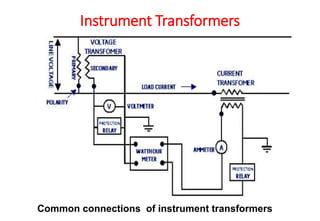
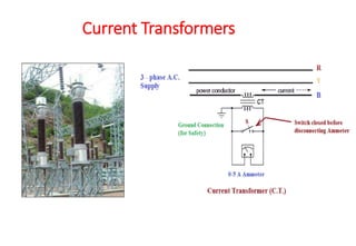
Instrument Transformers
What is an Instrument Transformer ?
• It is a transformer that is used in conjunction with any measuring
instrument (i.e., Ammeter, Voltmeter, Wattmeter, Watt-hour-
meter, …etc.)or protective equipment (i.e., Relays).
• It utilizes the current-transformation and voltage transformation
properties to measure high ac current and voltage.
Instrument Transformers
Instrument transformers are of two types:-
1. Current transformers (CT)
2. Potential transformers(PT)
Instrument Transformers
Applications of Instrument Transformers:
• For measurement of high ac current, it is usual to use low range ac
ammeter with suitable shunt.
• For measurement of high ac voltage, low range ac voltmeters are
used with high resistances connected in series.
• For measurement of very high ac current and voltage, we cannot
use these methods. Instead, we use specially constructed HV
instrument transformers to insulate the high voltage circuit from
the measuring circuit in order to protect the measuring instruments
from burning.
Instrument Transformers
Common connections of instrument transformers
Instrument Transformers
Current Transformers
Construction of C.T.:
• C.T. has a primary coil of one or more turns made of
thick wire connected in series with the line whose
current is to be measured.
• The secondary consists of a large number of turns made
of fine wire and is connected across an ammeter or a
relay’s terminals.
Current Transformers
Construction Types of Current Transformers
Window-type Bar-type
Function of CT:
• The principal function of a CT is to produce a proportional current
at a level of magnitude, which is suitable for the operation of low-
range measuring or protective devices such as indicating or
recording instruments and relays.
• The primary and secondary currents are expressed as a ratio such
as 100/5 or 1000/5 .
• With a 100/5 ratio CT, 100A flowing in the primary winding will
result in 5A flowing in the secondary winding, provided that the
correct rated burden is connected to the secondary winding.
• If we know the current ratio and the reading of an a.c. ammeter,
the primary current can be calculated as:
Current Transformers
Primary Current = CT ratio × ammeter reading
What is a Potential Transformer (PT) or (VT)?:
• A PT or sometimes called VT is a step-down transformer having many
primary turns but few secondary turns.
• In a step-down transformer the voltage decreases and the current
increases, thus voltage can be easily measured by using a low-range
voltmeter instrument.
• The voltage is stepped-down in a known ratio called the voltage ratio.
Potential Transformers
Construction and working of P.T.:
Construction
• A potential transformer has many primary winding turns but few number of
secondary winding turns that makes it a step-down transformer.
• A Voltmeter is connected to the secondary winding is usually a voltmeter of 150 V.
Working (Measurement):
• Primary terminals are connected in parallel across the line to which the voltage is
to be measured.
• The voltmeter reading gives the transformed value of the voltage across the
secondary terminals.
• The deflection of the voltmeter when divided by the transformed ratio gives the
actual voltage across the primary winding as:
The Line voltage = deflection / transformation-Ratio
Where transformation ratio = V2/V1
Potential Transformers
Precaution for P.T.:
• Since the secondary of a P.T. is connected to relays, their ratings
are usually 40 to 100 Watts.
• For safety purpose the secondary should be completely insulated
from the high voltage primary and should be in addition
grounded.
Potential Transformers
Types of P.T. :
Some types of p.t. are:
• Shell type
• Dry type
• Oil type
Rating Type
1. Below 5000 v Shell type
2. 5000-13800 v Dry type and oil type
3. Above 13800 v only oil type
Potential Transformers
Basic important rules for Instrument Transformers
Rule # 1
CTs are intended to be proportional current devices. Very high
voltages can result from open circuiting the secondary circuit of
an energized CT. Even very small primary currents can cause
damage.
Never open circuit a current
transformer secondary while the primary is energized
Never short circuit the secondary of an
energized VT
Rule # 2
VTs are intended to be used as proportional voltage
devices. Damaging current will result from short
circuiting the secondary circuit of an energized VT.
Rule # 3
CT secondary leads must be added to the CT
burden
Electronic relays usually represent very little burden
to the CT secondary circuit. In many cases the
major burden is caused by the CT secondary leads.
Rule # 4
Never use a 60 Hz rated VT
on a 50 Hz System
60 Hz VTs may saturate at lower frequencies and
exceed temperature limitations. VT failure is
likely…severe equipment damage is possible.

Instrument Transformers

  • 1.
  • 2.
    What is anInstrument Transformer ? • It is a transformer that is used in conjunction with any measuring instrument (i.e., Ammeter, Voltmeter, Wattmeter, Watt-hour- meter, …etc.)or protective equipment (i.e., Relays). • It utilizes the current-transformation and voltage transformation properties to measure high ac current and voltage. Instrument Transformers
  • 3.
    Instrument transformers areof two types:- 1. Current transformers (CT) 2. Potential transformers(PT) Instrument Transformers
  • 4.
    Applications of InstrumentTransformers: • For measurement of high ac current, it is usual to use low range ac ammeter with suitable shunt. • For measurement of high ac voltage, low range ac voltmeters are used with high resistances connected in series. • For measurement of very high ac current and voltage, we cannot use these methods. Instead, we use specially constructed HV instrument transformers to insulate the high voltage circuit from the measuring circuit in order to protect the measuring instruments from burning. Instrument Transformers
  • 5.
    Common connections ofinstrument transformers Instrument Transformers
  • 6.
  • 7.
    Construction of C.T.: •C.T. has a primary coil of one or more turns made of thick wire connected in series with the line whose current is to be measured. • The secondary consists of a large number of turns made of fine wire and is connected across an ammeter or a relay’s terminals. Current Transformers
  • 8.
    Construction Types ofCurrent Transformers Window-type Bar-type
  • 9.
    Function of CT: •The principal function of a CT is to produce a proportional current at a level of magnitude, which is suitable for the operation of low- range measuring or protective devices such as indicating or recording instruments and relays. • The primary and secondary currents are expressed as a ratio such as 100/5 or 1000/5 . • With a 100/5 ratio CT, 100A flowing in the primary winding will result in 5A flowing in the secondary winding, provided that the correct rated burden is connected to the secondary winding. • If we know the current ratio and the reading of an a.c. ammeter, the primary current can be calculated as: Current Transformers Primary Current = CT ratio × ammeter reading
  • 10.
    What is aPotential Transformer (PT) or (VT)?: • A PT or sometimes called VT is a step-down transformer having many primary turns but few secondary turns. • In a step-down transformer the voltage decreases and the current increases, thus voltage can be easily measured by using a low-range voltmeter instrument. • The voltage is stepped-down in a known ratio called the voltage ratio. Potential Transformers
  • 11.
    Construction and workingof P.T.: Construction • A potential transformer has many primary winding turns but few number of secondary winding turns that makes it a step-down transformer. • A Voltmeter is connected to the secondary winding is usually a voltmeter of 150 V. Working (Measurement): • Primary terminals are connected in parallel across the line to which the voltage is to be measured. • The voltmeter reading gives the transformed value of the voltage across the secondary terminals. • The deflection of the voltmeter when divided by the transformed ratio gives the actual voltage across the primary winding as: The Line voltage = deflection / transformation-Ratio Where transformation ratio = V2/V1 Potential Transformers
  • 12.
    Precaution for P.T.: •Since the secondary of a P.T. is connected to relays, their ratings are usually 40 to 100 Watts. • For safety purpose the secondary should be completely insulated from the high voltage primary and should be in addition grounded. Potential Transformers
  • 13.
    Types of P.T.: Some types of p.t. are: • Shell type • Dry type • Oil type Rating Type 1. Below 5000 v Shell type 2. 5000-13800 v Dry type and oil type 3. Above 13800 v only oil type Potential Transformers
  • 14.
    Basic important rulesfor Instrument Transformers Rule # 1 CTs are intended to be proportional current devices. Very high voltages can result from open circuiting the secondary circuit of an energized CT. Even very small primary currents can cause damage. Never open circuit a current transformer secondary while the primary is energized
  • 15.
    Never short circuitthe secondary of an energized VT Rule # 2 VTs are intended to be used as proportional voltage devices. Damaging current will result from short circuiting the secondary circuit of an energized VT.
  • 16.
    Rule # 3 CTsecondary leads must be added to the CT burden Electronic relays usually represent very little burden to the CT secondary circuit. In many cases the major burden is caused by the CT secondary leads.
  • 17.
    Rule # 4 Neveruse a 60 Hz rated VT on a 50 Hz System 60 Hz VTs may saturate at lower frequencies and exceed temperature limitations. VT failure is likely…severe equipment damage is possible.