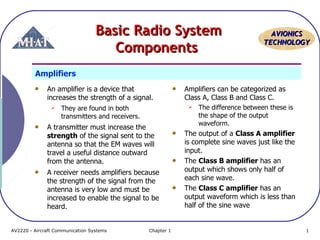
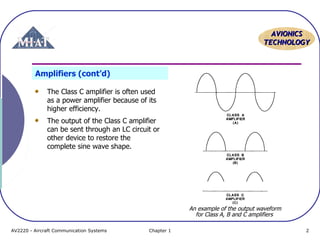
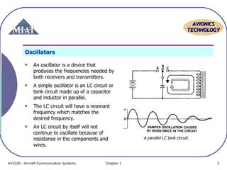
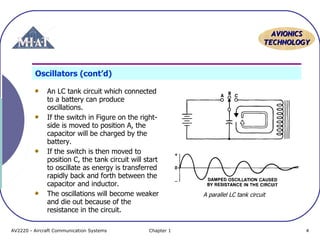
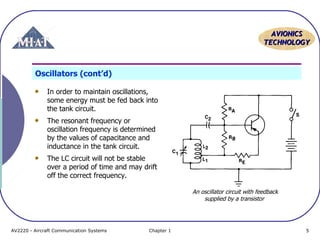
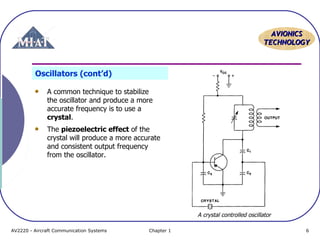
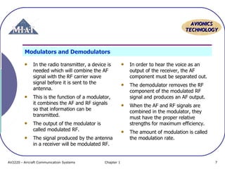
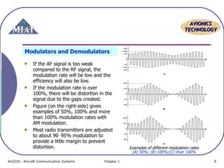
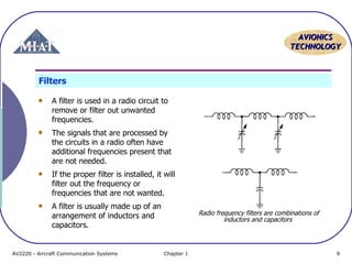
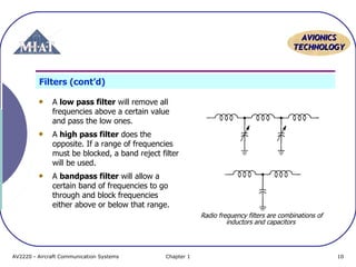
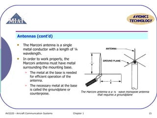
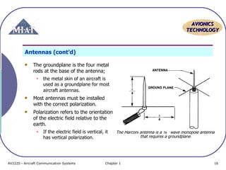
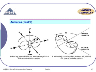
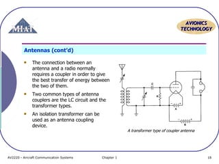
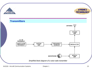
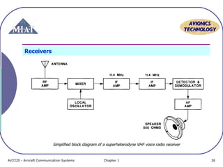
The document discusses basic radio system components including amplifiers, oscillators, modulators, demodulators, filters, antennas, tuning circuits, and transmitters and receivers. It provides details on each component's function and operating principles. Amplifiers are used to increase signal strength and come in classes A, B, and C. Oscillators produce frequencies using LC circuits that are stabilized using feedback or crystals. Modulators combine audio and radio frequencies while demodulators separate them. Antennas transmit and receive radio waves and come in types like dipoles and monopoles that have characteristics like polarization and directivity.
Aircraft Communication Topic 4 vhf communication systemIzah Asmadi
VHF communication systems are used for air traffic control and allow pilots to communicate with air traffic control centers, towers, and flight service stations. They operate between 118-151.975 MHz and communication is limited to line-of-sight. Modern VHF systems incorporate digital technology for reduced size and easier maintenance. Pilots select frequencies using a control panel that interfaces with a transceiver unit, which contains a receiver, transmitter, and antenna to send and receive radio signals.
Aircraft Communication Topic 6 pa systemIzah Asmadi
The document discusses aircraft audio control and public address systems. It describes how an audio control unit integrates and isolates audio signals from communication and navigation receivers, and allows selection of inputs and outputs. It provides audio to headsets and speakers. The public address system allows cockpit crew and flight attendants to make announcements to passengers through speakers in the cabin and lavatories. It has priority levels for different types of announcements. Call systems allow crew to communicate and alert each other through lights and sounds.
Aircraft Communication Topic 4 hf communication systemIzah Asmadi
HF communication systems operate between 2-30 MHz and are used for long-distance radio transmissions via ground waves. They are commonly found on larger aircraft to provide extended communication range with ground stations or other aircraft. A typical HF system consists of an HF transceiver and power amplifier located in the aircraft's electronics rack, an antenna, and a control head in the cockpit. The Rockwell Collins HF-220 is an example HF system that uses an automatic antenna coupler to tune the antenna across the operating frequency range.
VHF communication systems are used for air traffic control communications between aircraft and ground stations. They operate in the 118-136.975 MHz frequency range and use line-of-sight signals. Modern VHF systems have 720-760 channels and use digital technologies like ARINC 429 data buses for frequency selection and data transfer. VHF systems consist of a transceiver, control head, antennas, and interface to the aircraft audio system.
The document discusses the principles and operation of VOR (VHF Omni-directional Range) navigation. It explains that VOR stations transmit radio signals that allow aircraft receivers to determine their bearing from the station and navigate radials. The station transmits both a rotating signal and fixed reference signal, and the receiver compares the phase difference to calculate the radial. It provides details on how VOR radials are displayed on charts and how pilots can navigate to or from a station based on the radial indication.
Distance Measuring Equipment (DME) uses radio frequency signals to measure the distance between an aircraft and a ground station. The airborne DME unit includes a transmitter, receiver, timing circuits, and distance indicator. It sends interrogating signals to the ground station transponder, which includes a transmitter, decoder/encoder computer, receiver, and timing circuits. The DME calculates distance by measuring the round-trip travel time of signals and subtracting a fixed ground delay, then displays distance in nautical miles. DME allows pilots to determine their position by combining a VOR radial with a DME distance.
Aircraft Communication Topic 5 selcal and data link systemIzah Asmadi
The document describes Selcal technology used in aviation. Selcal allows ground operators to selectively call specific aircraft. It works by transmitting aircraft-specific tone combinations that are decoded by the aircraft's Selcal receiver. When the proper tones are received, the decoder alerts the flight crew via visual and audible signals. This allows crews to monitor radios only when their aircraft is being called, reducing workload. The document also provides details on how Selcal systems are implemented and their components.
This document provides summaries of various aviation navigation and safety systems, including:
- Automatic Direction Finder (ADF) which uses nondirectional radio beacons (NDBs) to determine direction;
- VHF Omni-directional Range (VOR) which provides navigation guidance from ground-based transmitters;
- Distance Measuring Equipment (DME) which measures slant distance from aircraft to ground stations;
- Instrument Landing System (ILS) which provides precision guidance for landing with localizer and glide slope signals;
- Traffic Collision Avoidance System (TCAS) which monitors nearby aircraft independently of air traffic control and warns pilots of potential collisions.
This document provides an overview of Distance Measuring Equipment (DME). It discusses how DME works by measuring the time it takes for a radio pulse to travel from an aircraft to a ground station to determine distance. It describes the components of DME systems, including the interrogator onboard aircraft, transponders at ground stations, and how pulses are coded and transmitted. It also provides specifics on the DME 415 and 435 systems in use at KAIA, including their components, capabilities, and associations with other navigation aids.
This document provides an overview of aircraft communication systems. It discusses the history of aircraft radio communication from World War I to modern times. It then describes the basic radio principles of transmission and reception using electromagnetic waves. It outlines the different frequency bands used for aircraft communication and navigation. It explains the main components and functions of transmitters and receivers. It also discusses different antenna types and their use on aircraft. Finally, it provides details on very high frequency (VHF) and high frequency (HF) communication systems, including system diagrams and their applications.
Robert Watson-Watt invented radar in the 1930s while working for the British government. He developed devices for detecting atmospheric discharges and locating approaching aircraft. This led to the development of radar which played a key role in Britain's defense during World War 2.
Radar systems use radio waves that are transmitted and reflected to detect objects. The components of a radar system include a transmitter, antenna, receiver, and indicator. The transmitter creates pulses that are emitted by the antenna. The receiver detects reflections and the indicator, usually a cathode ray tube, displays the results.
Air traffic control radars include Precision Approach Radar for precision landing, Airport Surveillance Radar for short range surveillance, Air Route Surveillance Radar for long
The document summarizes an aviation accident that occurred in 1996 near Delhi, India involving a mid-air collision between two aircraft that killed 349 people. It describes that one of the aircraft, KZA 1907, descended lower than its assigned altitude of 150 feet to 140 feet and below, colliding with another aircraft that was cleared to fly at 140 feet. The accident was deemed avoidable and led to new regulations requiring aircraft to have secondary surveillance radar and transponders to help air traffic control monitor aircraft positions and help prevent future collisions.
The document summarizes radio navigation systems used in aircraft, including VOR (VHF Omni-directional Range) and ADF (Automatic Direction Finder). It describes how VOR uses ground-based transmitters to provide bearing information to aircraft's VOR receivers. It also explains how ADF uses non-directional beacon ground transmitters and an aircraft's loop antenna to determine bearing to the transmitter. The document provides details on components, signals, and evolution of displays for both navigation aids. It emphasizes the importance of installation, maintenance, and calibration of radio navigation avionics for safety of flight.
The document discusses the Instrument Landing System (ILS), which provides aircraft with horizontal and vertical guidance just before and during landing. It has key components including localizer antennas that guide left/right movement and glide slope antennas that guide up/down movement. Marker beacons help pilots check aircraft position at certain distances from the runway. ILS allows landings in low visibility conditions down to Category III, with no visibility limitations. It transmits radio signals received by aircraft to indicate proper alignment on the landing path.
The document discusses various technologies used in air traffic control and air navigation, including navigation aids like VOR, ILS, DME, RNAV, and satellite navigation. It also covers flight planning, airport charts, approach charts, and the role of the flight management system.
The document provides information on Automatic Direction Finders (ADF) used for radio navigation. It discusses how ADFs use non-directional beacons and AM broadcast stations to provide a bearing to the pilot. It describes the principles of ADF navigation and antenna theory, explaining how a loop antenna and sense antenna are used to determine the direction of radio signals. It also provides details on ADF circuitry and installation techniques.
ALTITUDE. Vertical distance of an aircraft or object above a given reference, such as ground or sea level.
AMPLIFIER. An electronic device used to increase signal magnitude or power.
AMPLITUDE MODULATION (AM). A method of impressing a message upon a carrier signal by causing the carrier amplitude to vary proportionally to the message waveform.
ANTENNA SYSTEM. Routes RF energy from the transmitter, radiates the energy into space, receives echoes, and routes the echoes to the receiver.
A presentation prepared by my friend's friend. I have done no editing at all, I'm just uploading the presentation as it is.
The document provides an overview of an Instrument Landing System (ILS). It discusses that an ILS uses radio beams to guide aircraft visually during low visibility conditions. It has three main components - localizer antennas that provide horizontal guidance to the runway centerline, glide slope antennas that provide vertical guidance to the ideal 3-degree glidepath, and marker beacons that indicate the aircraft's distance from the runway. The document also describes the ILS categories which differ based on minimum decision heights and visibility requirements for landing.
- NDBs are older radio navigation systems that transmit low frequency signals used for en route and approach navigation. They provide reasonably accurate guidance at costs lower than other systems.
- An aircraft's ADF system uses a loop antenna to determine the direction to an NDB station based on signal strength. It has a fixed or movable indicator showing the relative bearing.
- Pilots can navigate to or from an NDB station by homing directly toward it or tracking a specific course using wind correction. Tracking involves adjusting the aircraft's heading to keep the needle deflection equal to the intercept angle in order to stay on course.
- ADF guidance can be affected by nighttime skywaves, signal fading, terrain interference, shore
Nav Topic 10 instrument landing systemsIzah Asmadi
The instrument landing system (ILS) allows pilots to land aircraft using instrument references even in low visibility conditions. The ILS provides both horizontal and vertical guidance to the runway using transmitters that emit radio signals received by the aircraft's instruments. Properly equipped aircraft can land using the ILS in near-zero visibility conditions. The ILS includes marker beacons that transmit tones to indicate the aircraft's distance from the runway. The localizer transmitter provides horizontal guidance by emitting left and right signals to keep the aircraft aligned with the runway centerline.
Distance Measuring Equipment (DME) power point Presentation for aircraftPrabhat K.C.
Distance Measuring Equipment (DME) is a measuring device using ground and air components to determine the slant range of an aircraft from a point.
It is a radio navigation technology that measures the slant range (distance) between an aircraft and a ground station by timing the propagation delay of radio signals in the frequency band between 960 and 1215 megahertz (MHz).
El documento describe los diferentes sistemas y equipos utilizados para el control aéreo, incluyendo el radar primario y secundario, el transpondedor Modo S, y sistemas como el TCAS. También analiza brevemente el caso de Venezuela, mencionando la regulación del espacio aéreo por parte del INAC y el uso de balizas a 406 MHz.
A brief description of how the PBN/RNAV concept works, together with an update of the FAA implementation programs for it in the US. This presentation has been made using public information only.
This slideshow was made for an invited talk at a local radio club that took place in early 2013. It introduces the methods of navigation and gives overview on the role of aerodrome and airspace traffic control.
This powerpoint has some copyrighted materials which I don't have copyright for. Please msg/comment to let me know so I can amend/delete it.
This document provides an overview of various navigation systems used in aviation, including Non-Directional Beacon (NDB), Automatic Direction Finder (ADF), VHF Omni-directional Range (VOR), Distance Measuring Equipment (DME), Instrument Landing System (ILS), marker beacons, radar, Global Positioning System (GPS), and approach lighting. It describes what each system is, how it functions, and its purpose in aiding pilot navigation.
The document discusses air traffic control and services. It aims to prevent collisions between aircraft during flight and on the ground through separating aircraft laterally and longitudinally based on distance and time. It describes control areas like aerodromes and traffic zones. It also discusses flight level assignment, area navigation systems, routes and waypoints to guide aircraft along planned paths.
This document discusses air-to-ground communication technologies and their limitations. It provides an overview of ACARS and its low-speed VHF data link. Newer technologies like VDLm2 and Iridium satellite allow for higher data rates but come at a higher cost. The document recommends Iridium for short haul aircraft given the upcoming increase in Iridium's data rates and the uncertainty around ACARS beyond 2020. It also reviews in-flight internet and mobile phone communication options using Swiftbroadband satellites.
A basic radio system consists of several key components:
1) Amplifiers are used in both transmitters and receivers to increase signal strength. Transmitter amplifiers boost the signal sent to the antenna while receiver amplifiers strengthen incoming weak signals.
2) Oscillators produce the carrier frequencies needed for transmission and reception using techniques like LC tank circuits and feedback. Crystal oscillators provide a more accurate frequency.
3) Modulators combine audio and radio frequencies to transmit information while demodulators separate these signals for audio output.
4) Filters, antennas, and tuning circuits work together to select the desired frequency and reject interference.
The document provides information about testing and repairing vehicle audio systems, including how AM and FM radio works, testing speaker polarity and impedance matching, diagnosing antennas, and types of speakers and crossovers. It explains that AM radio uses amplitude modulation while FM uses frequency modulation to transmit sound waves. Crossovers separate frequencies to send highs to tweeters and lows to woofers. Speaker polarity and impedance must match for best sound quality.
Aircraft Communication Topic 2 modulation and propagation of radio wavesIzah Asmadi
The document discusses different methods of modulation used in aviation communication, including amplitude modulation (AM), frequency modulation (FM), and single-sideband (SSB) modulation. It also describes how radio waves can propagate via different paths, such as surface waves, sky waves, and space waves, depending on the frequency of the radio transmission. The simplest form of modulation is on-off keying used for Morse code, while more advanced methods like AM, FM, and SSB are used to transmit voice and music signals. Radio waves at different frequencies propagate differently, with lower frequencies following the curvature of the Earth and higher frequencies traveling in straight lines.
Receivers are designed to receive electromagnetic waves transmitted from transmitters. The received signal passes through input circuits where it is filtered, amplified, and demodulated. It is then sent to output circuits like speakers or screens depending on the receiver's purpose. Receivers can be grouped as professional systems, specialized systems, or broadcasting receivers. They can also be classified by their schematic as direct amplification or superheterodyne receivers. The superheterodyne receiver mixes the input RF signal with a local oscillator to produce an intermediate frequency signal that is amplified before detection. This design makes superheterodyne receivers more sensitive and selective than other receiver types.
This document discusses radio transmitters and receivers. It explains that a radio transmitter consists of an oscillator that generates a carrier wave, a modulator that adds information to the carrier wave, an amplifier that increases the power of the modulated signal, and an antenna that radiates the signal as radio waves. A radio receiver uses an antenna to capture radio waves, a tuner to select the desired frequency, a detector to extract the information from the carrier wave, and amplifiers to strengthen the signal for playback. Modulation involves adding an input signal to a carrier wave to transmit information in a way that requires less power and antenna size than transmitting the input signal directly.
Nav Topic 2 modulation and propagation of radio wavesIzah Asmadi
The document discusses different types of radio wave modulation and propagation. It describes how a carrier wave carries information from the transmitter to the receiver using amplitude modulation (AM), frequency modulation (FM), or single sideband (SSB). It also explains the different paths radio waves can take, including surface waves, sky waves, and space waves, which depend on the frequency. Higher frequencies above 3 MHz use line-of-sight space wave propagation while lower frequencies may be reflected off the ionosphere as sky waves or follow the curvature of the Earth as surface waves. The length of the radio wave depends inversely on its frequency.
Radio technology uses electromagnetic waves to transmit information between locations. Early aircraft radios provided communications, while navigation systems developed later. Modern aircraft use radio for various purposes including communications, navigation, air traffic control, weather avoidance, approach guidance, altitude measurement, and collision avoidance. Radio waves are categorized into frequency bands from very low to extremely high, with aircraft systems using bands from very low to super high frequency.
This document discusses transistor amplifiers. It defines a transistor and amplifier, and describes how transistors can be used to faithfully amplify signals without changing their frequency or shape through proper biasing. It covers transistor types (NPN and PNP), components of transistor circuits like the emitter, base, and collector, and classifications of amplifiers. It also explains phase reversal in common emitter amplifiers, drawing load lines to represent transistor behavior, and calculating DC and AC equivalent circuits to analyze amplifier operation.
Electronics and Communication Engineering is the Branch of Engineering. Electronics and Communication Engineering field requires an understanding of core areas including Engineering Graphics, Computer Programming,Electronics Devices and Circuits-I, Network Analysis, Signals and Systems, Communication Systems, Electromagnetics Engineering, Digital Signal Processing, Embedded Systems, Microprocessor and Computer Architecture. Ekeeda offers Online Mechanical Engineering Courses for all the Subjects as per the Syllabus. Visit : https://ekeeda.com/streamdetails/stream/Electronics-and-Communication-Engineering
The document discusses audio system operation and diagnosis, including how AM/FM radio, satellite radio, Bluetooth, and voice recognition systems work. It covers electromagnetic and acoustic energy, radio wave terminology, modulation types, antennas, speakers, and causes of radio noise and interference. Diagnosis topics include testing antennas, speaker polarity and impedance matching.
This document summarizes a frequency modulated (FM) transmitter. It consists of a pre-amplifier to amplify audio from a microphone, which is then used to modulate the frequency of a tank circuit consisting of a coil and capacitor. The FM signal is converted to an electromagnetic wave and transmitted via an antenna. The transmitter keeps the carrier amplitude constant while varying its frequency according to the audio signal amplitude. Using transistors and passive components, the transmitter can transmit signals over an appreciable distance. It describes the basic blocks of the FM transmitter including the audio amplifier, RF oscillator, modulator, filters and power supply.
This document discusses the design and applications of multicavity klystron amplifiers. It begins by explaining how multicavity klystrons are able to make use of transit time instead of fighting it. It then provides details on the design of multicavity klystrons, including how they contain multiple cavities to improve bunching and efficiency. Finally, it discusses several applications of multicavity klystron amplifiers, including use in UHF-TV transmitters, satellite communication ground stations, radar transmission, and as power oscillators.
A low-level AM transmitter performs amplitude modulation early in the transmitter circuit, near the oscillator and buffer amplifier stages, where power levels are low. A high-level AM transmitter performs amplitude modulation in the final power amplifier stage, where higher power levels allow for greater transmission efficiency but limit the modulation to AM. Both approaches have advantages - low-level transmitters can produce different modulation types but are less efficient, while high-level transmitters are more efficient but restricted to AM modulation. The document discusses the components, signal paths, and operation of both low-level and high-level AM transmitter circuits.
The document discusses signal conditioning circuits used in biomedical recorders. It covers topics like:
- The requirements of biomedical amplifiers including high gain, avoiding distortion, and good frequency response.
- Types of amplifiers used like differential, AC coupled, and carrier amplifiers.
- What bio-amplifiers are and their purpose in amplifying low amplitude bio signals.
- The functional requirements of preamplifiers like boosting signal strength without degrading signal-to-noise ratio.
Nav Topic 1 basic radio wave propertiesIzah Asmadi
Radio waves are used in aircraft for communication and navigation. The document discusses the different frequency bands used for aviation purposes and the types of systems that operate in each band. Very low frequencies and low frequencies are used for long range navigation systems. Medium and high frequencies can travel long distances through ionospheric reflection and are used for over-ocean communication. Very high and ultra-high frequencies are line-of-sight and used for air traffic control communication and short range communication between aircraft.
The document discusses oscillators and feedback amplifiers. It defines positive and negative feedback, and describes their effects on gain. Oscillators generate an output signal without an external input through the use of positive feedback in an amplifier circuit. The two main types of oscillators are sinusoidal and non-sinusoidal oscillators. Common oscillator circuits discussed include the RC phase shift oscillator, Hartley oscillator, and common emitter amplifier configuration.
Modulation is the process of varying a high frequency carrier wave by an audio signal to allow audio transmission over long distances. In amplitude modulation (AM), the amplitude of the carrier wave is varied in proportion to the amplitude of the audio signal while keeping the carrier frequency and phase constant. This generates sideband frequencies above and below the carrier frequency that contain the audio information. The bandwidth of an AM signal is equal to twice the highest audio frequency. Modulation allows audio signals to be combined with high frequency radio waves for effective long-distance radio communication.
Electrical Engineering is the Branch of Engineering. Electrical Engineering field requires an understanding of core areas including Thermal and Hydraulics Prime Movers, Analog Electronic Circuits, Network Analysis and Synthesis, DC Machines and Transformers, Digital Electronic Circuits, Fundamentals of Power Electronics, Control System Engineering, Engineering Electromagnetics, Microprocessor and Microcontroller. Ekeeda offers Online Mechanical Engineering Courses for all the Subjects as per the Syllabus Visit : https://ekeeda.com/streamdetails/stream/Electrical-Engineering
Oscillators convert DC to AC signals using a feedback loop that sustains oscillations. Common oscillator circuits include LC, RC, quartz, and relaxation oscillators. The Hartley oscillator uses a tapped coil and capacitor in a feedback loop to generate radio frequencies. The Colpitts oscillator also uses an LC tank circuit but with capacitors in the feedback path. The Franklin oscillator uses two transistors and an LC circuit, with each transistor inverting the phase to sustain oscillations. The Wein bridge oscillator is an RC circuit that produces sine waves with high quality resonance and tuning capabilities. Oscillators are used to generate signals for applications like radio transmission, testing equipment, and sensors.
Electrical current, voltage, resistance, capacitance, and inductance are a few of the basic elements of electronics and radio. Apart from current, voltage, resistance, capacitance, and inductance, there are many other interesting elements to electronic technology. ... Use Electronics Notes to learn electronics online.
Similar to Aircraft Communication Topic 3 radio components (20)
Aircraft Communication Topic 7 elt, cvr and fdrIzah Asmadi
The document discusses emergency locator transmitters (ELTs) used in aircraft. It provides details on:
- How ELTs work, automatically transmitting a distress signal on two frequencies if the aircraft crashes.
- ELT system components including the transmitter, antenna, and battery designed to operate for 48 hours.
- Regulations requiring ELTs on most aircraft and procedures for testing, maintaining, and replacing batteries.
- The purpose of ELTs is to help search teams locate downed aircraft by transmitting a locating signal.
This document discusses how technology impacts business operations and stakeholders. It recognizes that technological advancements can deliver new capabilities before considering implications. Dramatic workplace changes over the last two decades like computing, the internet, email and messaging offer increased productivity but also complexity in evaluating performance and motivation. Issues around applying IT in business include privacy, recruitment practices, low-cost carriers shifting costs to passengers, and disposal of obsolete technology.
This document discusses four issues related to globalization, government relations, and ethical issues in business:
1) Whether "grease payments" are similar to bribery in influencing officials' decisions.
2) Whether the Malaysian government can enforce requiring halal logos on all food products.
3) The share-swapping deal between MAS and AirAsia and whether it benefits stakeholders.
4) Who has more right to be heard over the setting up of a Lynas plant near Kuantan - politicians or nearby residents.
Business ethics C5 -organizational_ethics_compatibility_mode_Izah Asmadi
This document discusses organizational ethics and addresses several ethical issues that can arise in different parts of an organization. It explains that organizational culture and ethical climate influence employee behavior and what is deemed acceptable. It then examines potential ethical challenges in various organizational functions like research and development, manufacturing, marketing, human resources, information technology, and more. Finally, it proposes some methods for building ethical safeguards into a company like implementing ethics policies and conducting ethics audits.
Business ethics C4 -corporate_social_responsibility_compatibility_mode_Izah Asmadi
This document discusses corporate social responsibility (CSR). It defines CSR as actions by organizations to achieve social benefits beyond profit and legal obligations. The document outlines the instrumental and social contract approaches to CSR management. It provides examples of CSR activities in Malaysia, such as fundraising campaigns. It then discusses six reasons for CSR, including business transparency, balancing corporate power with social responsibilities, and correcting social problems caused by business. The document concludes by outlining two broad CSR principles - the charity principle of voluntary aid to society and the stewardship principle of executives acting in the public's interest. It also describes three types of CSR: ethical, altruistic, and strategic.
Business ethics C3 theories principles in_business_ethicsIzah Asmadi
This document discusses business ethics from both normative and descriptive perspectives. Normative ethics focuses on principles and theories of right and wrong conduct, while descriptive ethics objectively describes people's actual moral beliefs and behaviors. The document also outlines several normative theories of business ethics, including stockholder theory, stakeholder theory, and social contract theory. Finally, it discusses key principles of business ethics in Islam derived from the Quran and Hadith, such as truthfulness, fairness, and avoiding exploitation.
Business ethics C1 -moral_ethics_ethical_dilemmaIzah Asmadi
This document discusses topics related to moral, ethics, and ethical dilemmas. It includes definitions of morality, ethics, values, and discusses the differences between morality and ethics. It provides hypothetical ethical dilemma cases for students to analyze, including an overcrowded lifeboat scenario, Sophie's choice, and a husband's choice case. Students are instructed to split into groups to analyze one of the three cases and answer questions about resolving the ethical dilemmas presented in each case.
Business ethics C2 -business_and_societyIzah Asmadi
1) The document outlines learning outcomes and definitions for a business ethics course. The learning outcomes are to identify stakeholders and explain the relationship between business and stakeholders.
2) It provides definitions for ethics, business ethics, and values from various sources and researchers. It also discusses why organizations exist and who they serve.
3) Business and society are described as an interactive system where business is part of society and business activities impact others. The document discusses stakeholders, market stakeholders, non-market stakeholders, and the nature of their interests and power.
This chapter discusses critical chain project scheduling and the theory of constraints. It explains how critical chain methodology addresses issues like variation, resource conflicts, and wasted safety margins that can cause delays. Key aspects covered include identifying the constraint or bottleneck, exploiting it by prioritizing projects, inserting buffers, and resolving conflicts to maximize throughput within the constraints. The chapter also reviews critiques of critical chain project management.
This chapter discusses project scheduling techniques including lagging activities, crashing projects, and developing activity networks. It covers applying lag relationships, constructing Gantt charts, accelerating projects through crashing or fast-tracking, understanding time-cost tradeoffs of crashing, and developing networks using both activity-on-node and activity-on-arrow approaches. The chapter aims to help readers schedule projects efficiently while understanding the costs and benefits of different techniques.
This chapter discusses key concepts for project scheduling including developing activity networks, estimating activity durations, calculating the critical path, and identifying ways to reduce the critical path. The chapter objectives are to understand scheduling terminology, create activity networks, estimate durations probabilistically, determine the critical path using forward and backward passes, identify float, calculate on-time probability under PERT, and understand how to reduce the critical path.
The document discusses project scope and scope management. It defines project scope as including all the work content and expected outcomes of a project. Scope management involves controlling the project goals, objectives, and consists of conceptual development, scope statement, work authorization, scope reporting, control systems, and project closeout. It provides details on each of these components, including defining problem statements, work breakdown structures, organizational breakdown structures, responsibility assignment matrices, and different types of contracts and control systems used in scope management.
The document discusses the importance of project cost management. It notes that projects historically have poor track records for meeting cost goals, with average cost overruns found in various CHAOS studies from 1995 to 2003. Proper project cost management, including processes like resource planning, cost estimating, cost budgeting and cost control, can help reduce cost overruns. The basic principles of cost management, such as distinguishing different types of costs and using techniques like activity-based costing and reserves, are also covered.
The document discusses building an effective project team. It begins by outlining 6 steps to building the team: 1) identify necessary skill sets, 2) identify people with the skills, 3) talk to potential team members, 4) negotiate with functional heads, 5) build in fallback positions, 6) assemble the team. It then discusses factors for effective project teams such as clear mission, trust, and enthusiasm. Finally, it lists 7 reasons why teams can fail such as unclear goals, poor communication, and high turnover.
The document discusses various aspects of leadership in project management, including the differences between managers and leaders, how project managers lead teams, traits of effective project leaders, the roles of project champions, and creating a professional culture of project management. It provides information on acquiring resources, communication, developing project managers, and the new competencies needed for project leadership.
Screening models help managers select projects from their pool using various criteria. Effective screening models are realistic, capable, flexible, easy to use, cost-effective, and allow comparability between projects. Approaches to screening include checklist models, simplified scoring models, analytic hierarchy process, profile models, and financial models like net present value, internal rate of return, and options models. Successful project portfolio management requires decision making, prioritization, review, realignment, and flexibility, while implementing portfolio management faces challenges from conservative communities, misaligned projects, unpromising projects, and scarce resources.
Embedded machine learning-based road conditions and driving behavior monitoringIJECEIAES
Car accident rates have increased in recent years, resulting in losses in human lives, properties, and other financial costs. An embedded machine learning-based system is developed to address this critical issue. The system can monitor road conditions, detect driving patterns, and identify aggressive driving behaviors. The system is based on neural networks trained on a comprehensive dataset of driving events, driving styles, and road conditions. The system effectively detects potential risks and helps mitigate the frequency and impact of accidents. The primary goal is to ensure the safety of drivers and vehicles. Collecting data involved gathering information on three key road events: normal street and normal drive, speed bumps, circular yellow speed bumps, and three aggressive driving actions: sudden start, sudden stop, and sudden entry. The gathered data is processed and analyzed using a machine learning system designed for limited power and memory devices. The developed system resulted in 91.9% accuracy, 93.6% precision, and 92% recall. The achieved inference time on an Arduino Nano 33 BLE Sense with a 32-bit CPU running at 64 MHz is 34 ms and requires 2.6 kB peak RAM and 139.9 kB program flash memory, making it suitable for resource-constrained embedded systems.
KuberTENes Birthday Bash Guadalajara - K8sGPT first impressionsVictor Morales
K8sGPT is a tool that analyzes and diagnoses Kubernetes clusters. This presentation was used to share the requirements and dependencies to deploy K8sGPT in a local environment.
Use PyCharm for remote debugging of WSL on a Windo cf5c162d672e4e58b4dde5d797...shadow0702a
This document serves as a comprehensive step-by-step guide on how to effectively use PyCharm for remote debugging of the Windows Subsystem for Linux (WSL) on a local Windows machine. It meticulously outlines several critical steps in the process, starting with the crucial task of enabling permissions, followed by the installation and configuration of WSL.
The guide then proceeds to explain how to set up the SSH service within the WSL environment, an integral part of the process. Alongside this, it also provides detailed instructions on how to modify the inbound rules of the Windows firewall to facilitate the process, ensuring that there are no connectivity issues that could potentially hinder the debugging process.
The document further emphasizes on the importance of checking the connection between the Windows and WSL environments, providing instructions on how to ensure that the connection is optimal and ready for remote debugging.
It also offers an in-depth guide on how to configure the WSL interpreter and files within the PyCharm environment. This is essential for ensuring that the debugging process is set up correctly and that the program can be run effectively within the WSL terminal.
Additionally, the document provides guidance on how to set up breakpoints for debugging, a fundamental aspect of the debugging process which allows the developer to stop the execution of their code at certain points and inspect their program at those stages.
Finally, the document concludes by providing a link to a reference blog. This blog offers additional information and guidance on configuring the remote Python interpreter in PyCharm, providing the reader with a well-rounded understanding of the process.
Advanced control scheme of doubly fed induction generator for wind turbine us...IJECEIAES
This paper describes a speed control device for generating electrical energy on an electricity network based on the doubly fed induction generator (DFIG) used for wind power conversion systems. At first, a double-fed induction generator model was constructed. A control law is formulated to govern the flow of energy between the stator of a DFIG and the energy network using three types of controllers: proportional integral (PI), sliding mode controller (SMC) and second order sliding mode controller (SOSMC). Their different results in terms of power reference tracking, reaction to unexpected speed fluctuations, sensitivity to perturbations, and resilience against machine parameter alterations are compared. MATLAB/Simulink was used to conduct the simulations for the preceding study. Multiple simulations have shown very satisfying results, and the investigations demonstrate the efficacy and power-enhancing capabilities of the suggested control system.
International Conference on NLP, Artificial Intelligence, Machine Learning an...gerogepatton
International Conference on NLP, Artificial Intelligence, Machine Learning and Applications (NLAIM 2024) offers a premier global platform for exchanging insights and findings in the theory, methodology, and applications of NLP, Artificial Intelligence, Machine Learning, and their applications. The conference seeks substantial contributions across all key domains of NLP, Artificial Intelligence, Machine Learning, and their practical applications, aiming to foster both theoretical advancements and real-world implementations. With a focus on facilitating collaboration between researchers and practitioners from academia and industry, the conference serves as a nexus for sharing the latest developments in the field.
Batteries -Introduction – Types of Batteries – discharging and charging of battery - characteristics of battery –battery rating- various tests on battery- – Primary battery: silver button cell- Secondary battery :Ni-Cd battery-modern battery: lithium ion battery-maintenance of batteries-choices of batteries for electric vehicle applications.
Fuel Cells: Introduction- importance and classification of fuel cells - description, principle, components, applications of fuel cells: H2-O2 fuel cell, alkaline fuel cell, molten carbonate fuel cell and direct methanol fuel cells.
Software Engineering and Project Management - Introduction, Modeling Concepts...Prakhyath Rai
Introduction, Modeling Concepts and Class Modeling: What is Object orientation? What is OO development? OO Themes; Evidence for usefulness of OO development; OO modeling history. Modeling
as Design technique: Modeling, abstraction, The Three models. Class Modeling: Object and Class Concept, Link and associations concepts, Generalization and Inheritance, A sample class model, Navigation of class models, and UML diagrams
Building the Analysis Models: Requirement Analysis, Analysis Model Approaches, Data modeling Concepts, Object Oriented Analysis, Scenario-Based Modeling, Flow-Oriented Modeling, class Based Modeling, Creating a Behavioral Model.
Introduction- e - waste – definition - sources of e-waste– hazardous substances in e-waste - effects of e-waste on environment and human health- need for e-waste management– e-waste handling rules - waste minimization techniques for managing e-waste – recycling of e-waste - disposal treatment methods of e- waste – mechanism of extraction of precious metal from leaching solution-global Scenario of E-waste – E-waste in India- case studies.
The CBC machine is a common diagnostic tool used by doctors to measure a patient's red blood cell count, white blood cell count and platelet count. The machine uses a small sample of the patient's blood, which is then placed into special tubes and analyzed. The results of the analysis are then displayed on a screen for the doctor to review. The CBC machine is an important tool for diagnosing various conditions, such as anemia, infection and leukemia. It can also help to monitor a patient's response to treatment.
1. AAVVIIOONNIICCSS
TTEECCHHNNOOLLOOGGYY
BBaassiicc RRaaddiioo SSyysstteemm
CCoommppoonneennttss
Amplifiers
An amplifier is a device that
increases the strength of a signal.
They are found in both
transmitters and receivers.
A transmitter must increase the
strength of the signal sent to the
antenna so that the EM waves will
travel a useful distance outward
from the antenna.
A receiver needs amplifiers because
the strength of the signal from the
antenna is very low and must be
increased to enable the signal to be
heard.
Amplifiers can be categorized as
Class A, Class B and Class C.
The difference between these is
the shape of the output
waveform.
The output of a Class A amplifier
is complete sine waves just like the
input.
The Class B amplifier has an
output which shows only half of
each sine wave.
The Class C amplifier has an
output waveform which is less than
half of the sine wave
AV2220 - Aircraft Communication Systems Chapter 1 1
2. AAVVIIOONNIICCSS
TTEECCHHNNOOLLOOGGYY
Amplifiers (cont’d)
The Class C amplifier is often used
as a power amplifier because of its
higher efficiency.
The output of the Class C amplifier
can be sent through an LC circuit or
other device to restore the
complete sine wave shape.
An example of the output waveform
for Class A, B and C amplifiers
AV2220 - Aircraft Communication Systems Chapter 1 2
3. AAVVIIOONNIICCSS
TTEECCHHNNOOLLOOGGYY
Oscillators
An oscillator is a device that
produces the frequencies needed by
both receivers and transmitters.
A simple oscillator is an LC circuit or
tank circuit made up of a capacitor
and inductor in parallel.
The LC circuit will have a resonant
frequency which matches the
desired frequency.
An LC circuit by itself will not
continue to oscillate because of
resistance in the components and
wires.
A parallel LC tank circuit.
AV2220 - Aircraft Communication Systems Chapter 1 3
4. AAVVIIOONNIICCSS
TTEECCHHNNOOLLOOGGYY
Oscillators (cont’d)
An LC tank circuit which connected
to a battery can produce
oscillations.
If the switch in Figure on the right-side
is moved to position A, the
capacitor will be charged by the
battery.
If the switch is then moved to
position C, the tank circuit will start
to oscillate as energy is transferred
rapidly back and forth between the
capacitor and inductor.
The oscillations will become weaker
and die out because of the
resistance in the circuit.
A parallel LC tank circuit
AV2220 - Aircraft Communication Systems Chapter 1 4
5. AAVVIIOONNIICCSS
TTEECCHHNNOOLLOOGGYY
Oscillators (cont’d)
In order to maintain oscillations,
some energy must be fed back into
the tank circuit.
The resonant frequency or
oscillation frequency is determined
by the values of capacitance and
inductance in the tank circuit.
The LC circuit will not be stable
over a period of time and may drift
off the correct frequency.
An oscillator circuit with feedback
supplied by a transistor
AV2220 - Aircraft Communication Systems Chapter 1 5
6. AAVVIIOONNIICCSS
TTEECCHHNNOOLLOOGGYY
Oscillators (cont’d)
A common technique to stabilize
the oscillator and produce a more
accurate frequency is to use a
crystal.
The piezoelectric effect of the
crystal will produce a more accurate
and consistent output frequency
from the oscillator.
A crystal controlled oscillator
AV2220 - Aircraft Communication Systems Chapter 1 6
7. AAVVIIOONNIICCSS
TTEECCHHNNOOLLOOGGYY
Modulators and Demodulators
In the radio transmitter, a device is
needed which will combine the AF
signal with the RF carrier wave
signal before it is sent to the
antenna.
This is the function of a modulator,
it combines the AF and RF signals
so that information can be
transmitted.
The output of the modulator is
called modulated RF.
The signal produced by the antenna
in a receiver will be modulated RF.
In order to hear the voice as an
output of the receiver, the AF
component must be separated out.
The demodulator removes the RF
component of the modulated RF
signal and produces an AF output.
When the AF and RF signals are
combined in the modulator, they
must have the proper relative
strengths for maximum efficiency.
The amount of modulation is called
the modulation rate.
AV2220 - Aircraft Communication Systems Chapter 1 7
8. AAVVIIOONNIICCSS
TTEECCHHNNOOLLOOGGYY
Modulators and Demodulators
If the AF signal is too weak
compared to the RF signal, the
modulation rate will be low and the
efficiency will also be low.
If the modulation rate is over
100%, there will be distortion in the
signal due to the gaps created.
Figure (on the right-side) gives
examples of 50%, 100% and more
than 100% modulation rates with
AM modulation.
Most radio transmitters are adjusted
to about 90‑95% modulation to
provide a little margin to prevent
distortion.
Examples of different modulation rates
(A) 50%; (B) 100%;(C) Over 100%
AV2220 - Aircraft Communication Systems Chapter 1 8
9. AAVVIIOONNIICCSS
TTEECCHHNNOOLLOOGGYY
Filters
A filter is used in a radio circuit to
remove or filter out unwanted
frequencies.
The signals that are processed by
the circuits in a radio often have
additional frequencies present that
are not needed.
If the proper filter is installed, it will
filter out the frequency or
frequencies that are not wanted.
A filter is usually made up of an
arrangement of inductors and
capacitors.
Radio frequency filters are combinations of
inductors and capacitors
AV2220 - Aircraft Communication Systems Chapter 1 9
10. AAVVIIOONNIICCSS
TTEECCHHNNOOLLOOGGYY
Filters (cont’d)
A low pass filter will remove all
frequencies above a certain value
and pass the low ones.
A high pass filter does the
opposite. If a range of frequencies
must be blocked, a band reject filter
will be used.
A bandpass filter will allow a
certain band of frequencies to go
through and block frequencies
either above or below that range.
Radio frequency filters are combinations of
inductors and capacitors
AV2220 - Aircraft Communication Systems Chapter 1 10
11. AAVVIIOONNIICCSS
TTEECCHHNNOOLLOOGGYY
Antennas
An antenna is a device that
transforms electrical signals into EM
waves in the case of a transmit
antenna, or transforms EM waves
into electrical signals in the case of
a receive antenna.
An antenna may be used for
transmit only, receive only, or both,
depending on the particular radio
system involved.
The maintenance, inspection and
installation of antennas are usually
the responsibility of the airframe
technician since they are attached
to the structure or skin of the
aircraft.
Three characteristics of an antenna
are critical:
length,
polarization
directivity.
For an antenna to be most efficient,
its length must be one-half the
wavelength of the signal being
transmitted or received.
This length allows the antenna
current to be maximum.
AV2220 - Aircraft Communication Systems Chapter 1 11
12. AAVVIIOONNIICCSS
TTEECCHHNNOOLLOOGGYY
Antennas (cont’d)
To induce the maximum amount of
voltage into the receiving antenna,
the antenna must be installed in
such away that it is:
perpendicular to the magnetic,
H, field in the radio waves.
parallel to the electric, E, field
in the radio waves.
When the transmitting antenna is
vertical, the E field is vertical, and
the radiation is said to be
vertically polarized.
The maximum reception is picked
up with a vertical antenna.
When the transmitting antenna is
horizontal, the radiation is
horizontally polarized, and is
best received on a horizontal
antenna.
When the transmitting antenna is
vertical, its electric field is vertical
and the magnetic field is horizontal.
It is picked up best by a vertical
antenna.
Most LF, MF, and HF
communication use horizontally
polarized antennas, and
Higher frequency systems use
vertically polarized antennas.
AV2220 - Aircraft Communication Systems Chapter 1 12
13. AAVVIIOONNIICCSS
TTEECCHHNNOOLLOOGGYY
Antennas (cont’d)
The dipole antenna in A transmits
its signal strongest in a direction
perpendicular to its length.
The vertical whip antenna in B has
a uniform field strength in all
directions and is called an
onmidirectional antenna.
The loop antenna in C is highly
directional.
Its strength is sharply reduced in
the direction perpendicular to its
plane.
Directional characteristics of typical antennas
AV2220 - Aircraft Communication Systems Chapter 1 13
14. AAVVIIOONNIICCSS
TTEECCHHNNOOLLOOGGYY
Antennas (cont’d)
Antennas often have general names
that describe some of their basic
characteristics.
Two of the more common types are
the Hertz dipole antenna and the
Marconi monopole antenna.
The Hertz dipole antenna has two
metal conductors in a straight line
with the connection in the middle.
It is called a half‑wave
antenna because the overall
length is equal to one half the
wavelength of the EM wave it is
designed to be used with.
The Hertz dipole antenna is a half‑wave antenna
AV2220 - Aircraft Communication Systems Chapter 1 14
15. AAVVIIOONNIICCSS
TTEECCHHNNOOLLOOGGYY
Antennas (cont’d)
The Marconi antenna is a single
metal conductor with a length of ¼
wavelength.
In order to work properly, the
Marconi antenna must have metal
surrounding the mounting base.
The metal at the base is needed
for efficient operation of the
antenna.
The necessary metal at the base
is called the groundplane or
counterpoise.
The Marconi antenna is a ¼ ‑wave monopole antenna
that requires a groundplane
AV2220 - Aircraft Communication Systems Chapter 1 15
16. AAVVIIOONNIICCSS
TTEECCHHNNOOLLOOGGYY
Antennas (cont’d)
The groundplane is the four metal
rods at the base of the antenna;
the metal skin of an aircraft is
used as a groundplane for most
aircraft antennas.
Most antennas must be installed
with the correct polarization.
Polarization refers to the orientation
of the electric field relative to the
earth.
If the electric field is vertical, it
has vertical polarization.
The Marconi antenna is a ¼ ‑wave monopole antenna
that requires a groundplane
AV2220 - Aircraft Communication Systems Chapter 1 16
17. AAVVIIOONNIICCSS
TTEECCHHNNOOLLOOGGYY
Antennas (cont’d)
A horizontally polarized Hertz antenna will produce
this type of radiation pattern
A vertically polarized Marconi antenna will produce
this type of radiation pattern
AV2220 - Aircraft Communication Systems Chapter 1 17
18. AAVVIIOONNIICCSS
TTEECCHHNNOOLLOOGGYY
Antennas (cont’d)
The connection between an
antenna and a radio normally
requires a coupler in order to give
the best transfer of energy between
the two of them.
Two common types of antenna
couplers are the LC circuit and the
transformer types.
An isolation transformer can be
used as an antenna coupling
device.
A transformer type of coupler antenna
AV2220 - Aircraft Communication Systems Chapter 1 18
19. AAVVIIOONNIICCSS
TTEECCHHNNOOLLOOGGYY
Antennas (cont’d)
The use of an LC circuit as a
coupler between the coax and
antenna is shown in Figure below.
In the past, long-wire trailing
antennas were used for HF
communication.
But advances in communication
technology have developed tuned
antennas that are actually part of
the aircraft structure.
Other aircraft use a copper-clad
steel wire enclosed in a
polyethylene covering run from
outside the fuselage above the
cockpit to the top of the vertical fin.
An LC circuit used as an antenna coupler
AV2220 - Aircraft Communication Systems Chapter 1 19
20. AAVVIIOONNIICCSS
TTEECCHHNNOOLLOOGGYY
Antennas (cont’d)
VHF communication uses the
frequencies between 118 and 136
megahertz, which are just above
the VOR frequencies, and the
antenna used is normally a
quarter-wavelength, vertically
polarized whip.
The metal in the aircraft structure
provides the other quarter-wavelength
to make the antenna
electrically a half-wavelength long.
Many whip antennas are bent so
they can also pick up horizontally
polarized signals.
Broad-band blade antennas provide
more efficient transmission and
reception than simple whips.
AV2220 - Aircraft Communication Systems Chapter 1 20
21. AAVVIIOONNIICCSS
TTEECCHHNNOOLLOOGGYY
Tuning Circuits
An antenna will intercept many
different EM waves of different
frequencies so some method must
be used to separate out the desired
frequency.
The tuning circuit performs this
function.
As the tuning knob is rotated on the
radio, it moves the variable
capacitor until the resonant
frequency of the circuit matches the
frequency of the desired station.
This signal is passed into the
radio and the other frequencies
are blocked out.
A simple tuning circuit which consists of
a variable capacitor and an inductor in parallel
AV2220 - Aircraft Communication Systems Chapter 1 21
22. AAVVIIOONNIICCSS
TTEECCHHNNOOLLOOGGYY
Tuning Circuits (cont’d)
A better type of tuner which is
found on most modern radios uses
a frequency synthesizer which
contains a number of crystals that
can be combined to match the
desired frequency.
Each crystal has a particular
frequency and by using switches
the crystals can be combined to
produce many additional
frequencies.
When two frequencies are
combined, two new frequencies are
created that are equal to the sum
and the difference of the two
frequencies.
The basic operation of a frequency synthesizer
AV2220 - Aircraft Communication Systems Chapter 1 22
24. AAVVIIOONNIICCSS
TTEECCHHNNOOLLOOGGYY
Transmitters (cont’d)
A simple voice radio transmitter consists of:
Frequency oscillator which operates at one half the carrier frequency
Buffer amplifier and frequency doubler which assigned to amplify and doubling
the signal so that it has enough power to radiate into space when it goes to the
antenna.
The modulator combines the AF and RF signals
The power amp which operates to amplify signal before being sent down the
coax to the antenna.
The transmitter uses a crystal oscillator to produce an accurately controlled
carrier frequency, and only this one frequency radiates from the transmitter
antenna.
In order for a receiver to be useful, it must filter out every frequency except the
one that is wanted.
To do this, it employs a special superheterodyne circuit.
AV2220 - Aircraft Communication Systems Chapter 1 24
25. AAVVIIOONNIICCSS
TTEECCHHNNOOLLOOGGYY
Receivers
In the 1920s, a new type of radio receiver was invented that produced
better sound quality.
It was called the superheterodyne or superhet radio.
The only major difference between the superhet and earlier radios was
that it reduced the modulated RF signal from the antenna to an AF
signal in more than one jump or stage.
AV2220 - Aircraft Communication Systems Chapter 1 25
27. AAVVIIOONNIICCSS
TTEECCHHNNOOLLOOGGYY
Receivers (cont’d)
In a VHF superhet aircraft receiver block diagram above:
The RF signal from the antenna is combined with a local oscillator frequency to
produce a lower IF frequency.
The intermediate frequencies found in a superhet radio are abbreviated as IF.
The output of the mixer is the difference between the RF frequency and the
local oscillator frequency.
The basic principle of the mixer is:
two different frequencies are combined,
two new frequencies are created; the sum and the difference of the two
combined frequencies.
The IF signals is amplified and then sent to the detector and demodulator.
The detector chops off half of each sine wave to produce a varying DC signal
from an AC signal.
The AF signal is amplified and used to drive the speaker.
AV2220 - Aircraft Communication Systems Chapter 1 27
28. AAVVIIOONNIICCSS
TTEECCHHNNOOLLOOGGYY
Receivers (cont’d)
A tunable local oscillator is included
in this circuit.
The frequency of this oscillator is
varied so it is always a specific
frequency higher than the
frequency to which the
preamplifier is tuned.
For most broadcast band receivers,
the frequency of the local oscillator
is always 455 kilohertz higher than
the frequency tuned on the
preamplifier.
In this case, the local oscillator
produces a signal with a
frequency of 1,655 kilohertz
(1,200 + 455).
The antenna picks up all the radio
signals in the area and they are
taken into a tunable preamplifier.
This preamplifier uses an
electronic filter circuit that passes
only the frequency to which the
receiver is tuned and sends all of
the other frequencies to ground.
The preamplifier amplifies any
signal with a frequency of e.g.
1,200 kHz and passes all other
frequencies to ground.
AV2220 - Aircraft Communication Systems Chapter 1 28
29. AAVVIIOONNIICCSS
TTEECCHHNNOOLLOOGGYY
Receivers (cont’d)
The four signals will have
frequencies of:
1,200 kHz
1,655 kHz
2,855 kHz (1,200 + 1,655)
455 kHz (1,655 - 1,200)
The four signals from the mixer are
sent into the intermediate
frequency (IF) amplifier.
This is a very narrow-band amplifier
that is tuned to 455 kHz.
It amplifies the 455 kHz signal and
attenuates, or diminishes, all other
frequencies.
The signals from the preamplifier
and the local oscillator are sent to
the mixer.
When signals with two frequencies
are mixed, they produce two other
signals:
one with a frequency that is the
sum of the original two
frequencies and
the other with a frequency that is
the difference between the two.
AV2220 - Aircraft Communication Systems Chapter 1 29
30. AAVVIIOONNIICCSS
TTEECCHHNNOOLLOOGGYY
Receivers (cont’d)
The amplified 455 kHz signal is sent to the detector/demodulator
It removes the 455 kHz IF carrier and leaves the AF envelope that has both
halves of the audio signal.
The detector rectifies the AF signal and removes one half of the envelope.
The AF signal is amplified by a power amplifier stage and drives the speaker.
The output of the speaker is the same as the input to the microphone at the
transmitter.
AV2220 - Aircraft Communication Systems Chapter 1 30
31. AAVVIIOONNIICCSS
TTEECCHHNNOOLLOOGGYY
Receivers (cont’d)
Communication receivers such as those used in aircraft are more sensitive than
the normal household broadcast receiver, and they have more stages.
A simplified block diagram of a VHF superhet communication receiver
AV2220 - Aircraft Communication Systems Chapter 1 31
32. AAVVIIOONNIICCSS
TTEECCHHNNOOLLOOGGYY
Receivers (cont’d)
The signal is picked up on the
antenna and amplified by the tuned
preamplifier.
The local oscillator produces a
frequency that is 10.8-megahertz
different from the frequency to
which the preamplifier is tuned.
These two frequencies are fed into
the mixer where they produce a
10.8-MHz intermediate frequency.
This IF is amplified by two stages of
IF amplification and sent into the
detector/demodulator, where it
emerges as an audio frequency
signal that duplicates the AF
produced by the microphone at the
transmitter.
Some of the detector output is sent
into a squelch circuit that controls
the audio frequency amplifier.
When no signal is being received,
the AF amplifier output is
attenuated, or decreased, so the
background noise that makes a
hissing sound in the speaker is not
loud enough to be annoying.
AV2220 - Aircraft Communication Systems Chapter 1 32
33. AAVVIIOONNIICCSS
TTEECCHHNNOOLLOOGGYY
Speakers and Microphones
Aircraft radios often supply an audio
output for the pilot and voice
transmitters require an audio input
from a microphone.
A speaker is a device that
transforms electrical signals into
sound waves.
When the audio frequency signal is
applied to the windings in the
speaker, it sets up a magnetic field
that expands and contracts at an
audio rate.
A dynamic speaker
AV2220 - Aircraft Communication Systems Chapter 1 33
34. AAVVIIOONNIICCSS
TTEECCHHNNOOLLOOGGYY
Speakers and Microphones (cont’d)
The magnetic field causes the metal
diaphragm to vibrate at a
corresponding rate to produce the
movement of air that generates
sound waves.
Dynamic microphones are available
which operate in the opposite way.
Many newer and more efficient
types of microphones are now
being manufactured, but they all
work by transforming the vibrations
of sound waves into varying
electrical signals.
A dynamic speaker
AV2220 - Aircraft Communication Systems Chapter 1 34
35. AAVVIIOONNIICCSS
TTEECCHHNNOOLLOOGGYY
Audio Control Panel
When an aircraft has more than one
radio, an efficient means of
switching the microphone and
speaker connections from one radio
to another is needed.
The audio control panel performs
this function.
An audio control panel is not a radio
because it only uses audio
frequencies, but it is associated
with the radios in the aircraft.
A typical audio control panel
AV2220 - Aircraft Communication Systems Chapter 1 35
36. AAVVIIOONNIICCSS
TTEECCHHNNOOLLOOGGYY
Audio Control Panel (cont’d)
This audio control panel has a row
of toggle switches that can be used
to connect the audio output of the
various radios to the speaker or
headphones.
It also has a rotary selector switch
to connect the microphone audio
output to the different radio
transmitters and intercom systems
available for the aircraft.
The audio control panel illustrated
also has three lights that are the
indicators for the marker beacon
system on the aircraft.
A typical audio control panel
AV2220 - Aircraft Communication Systems Chapter 1 36
37. AAVVIIOONNIICCSS
TTEECCHHNNOOLLOOGGYY
RReegguullaattiioonnss aanndd
SSttaannddaarrddss ffoorr RRaaddiiooss
Aircraft avionics equipment might
have to comply with a number of
different regulations and standards
depending on the type of
equipment and the type of aircraft
in which it is installed.
Regulations from the FAA and the
FCC apply to the manufacture and
use of most types of equipment and
carry the force of law.
FAA standards for equipment are
usually in the form of TSO
(Technical Standard Order)
approvals.
FCC rules generally apply to
equipment which produces radio
waves.
An FCC Station License is required
for aircraft that have radio
transmitters other than ELT.
Each different type of transmitter
must be listed on the license that is
displayed in the cockpit.
The role of ARINC in established
standards apply to the equipment in
air carrier jets and bizjets primarily.
There are some FAA Regulations
concerning the use of radio
equipment in flight.
AV2220 - Aircraft Communication Systems Chapter 1 37
38. AAVVIIOONNIICCSS
TTEECCHHNNOOLLOOGGYY
FAR 91.130 (c)
No person may operate an aircraft in an Airport Radar Service Area (ARSA)
unless two‑way radio communication is established and maintained with ATC.
A transponder with Mode C automatic reporting of aircraft pressure altitude is
also required in all ARSAs.
FAR 91.131 (c) and (d)
No person may operate an aircraft in a Terminal Control Area (TCA) unless it
has:
1. A two‑way radio with appropriate frequencies available.
2. An operable transponder with Mode C altitude reporting.
AV2220 - Aircraft Communication Systems Chapter 1 38
39. AAVVIIOONNIICCSS
TTEECCHHNNOOLLOOGGYY
FAR 91.205 (d) and (e) Minimum Equipment Requirements for
IFR
Two‑way radio communications and navigation equipment appropriate to the
ground facilities that will be used.
At and above 24,000 ft. MSL; approved DME (distance measuring equipment).
AV2220 - Aircraft Communication Systems Chapter 1 39
40. AAVVIIOONNIICCSS
TTEECCHHNNOOLLOOGGYY
FAR 91.511
Large and turbine ‑powered, multi‑engine airplanes, if operating over water
more than 30 minutes or 100 nautical miles from the nearest shoreline, must
have:
1. Radio communication equipment appropriate to the ground facilities.
2. Two transmitters.
3. Two microphones.
4. Two headsets (or headset and speaker).
5. Two independent receivers.
6. If needed, one HF transceiver.
AV2220 - Aircraft Communication Systems Chapter 1 40