Download as PDF, PPTX
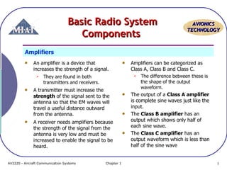

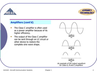
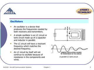
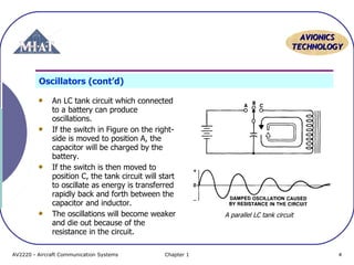
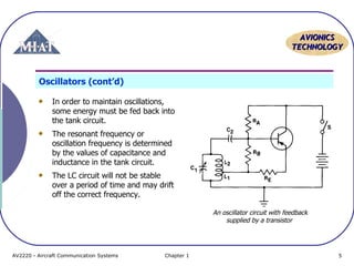
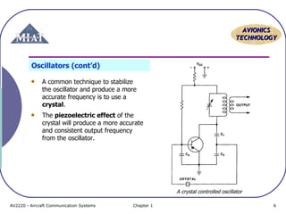
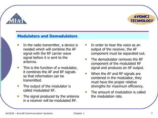
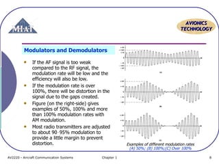
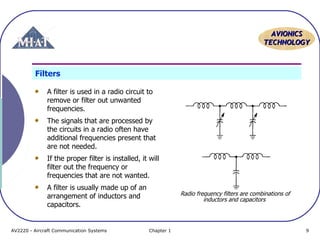
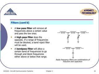
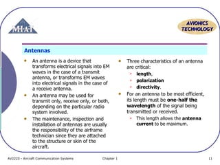

A basic radio system consists of several key components: 1) Amplifiers are used in both transmitters and receivers to increase signal strength. Transmitter amplifiers boost the signal sent to the antenna while receiver amplifiers strengthen incoming weak signals. 2) Oscillators produce the carrier frequencies needed for transmission and reception using techniques like LC tank circuits and feedback. Crystal oscillators provide a more accurate frequency. 3) Modulators combine audio and radio frequencies to transmit information while demodulators separate these signals for audio output. 4) Filters, antennas, and tuning circuits work together to select the desired frequency and reject interference.