Download as PDF, PPTX
![AAVVIIOONNIICCSS
TTEECCHHNNOOLLOOGGYY
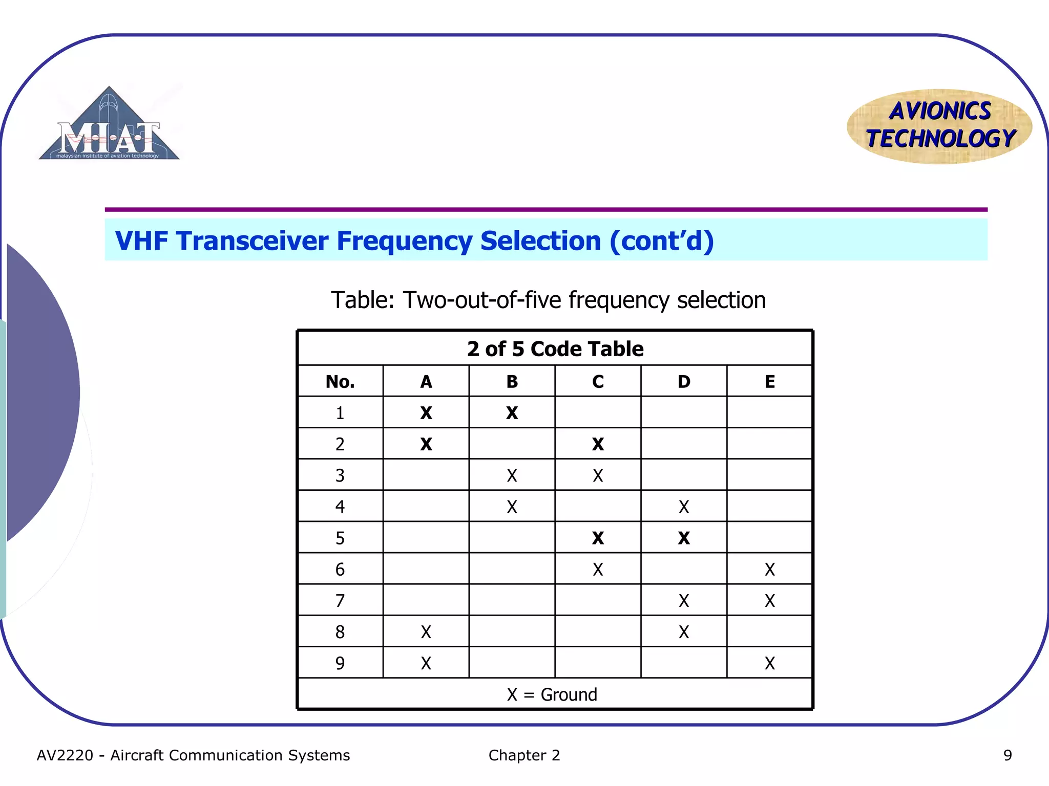
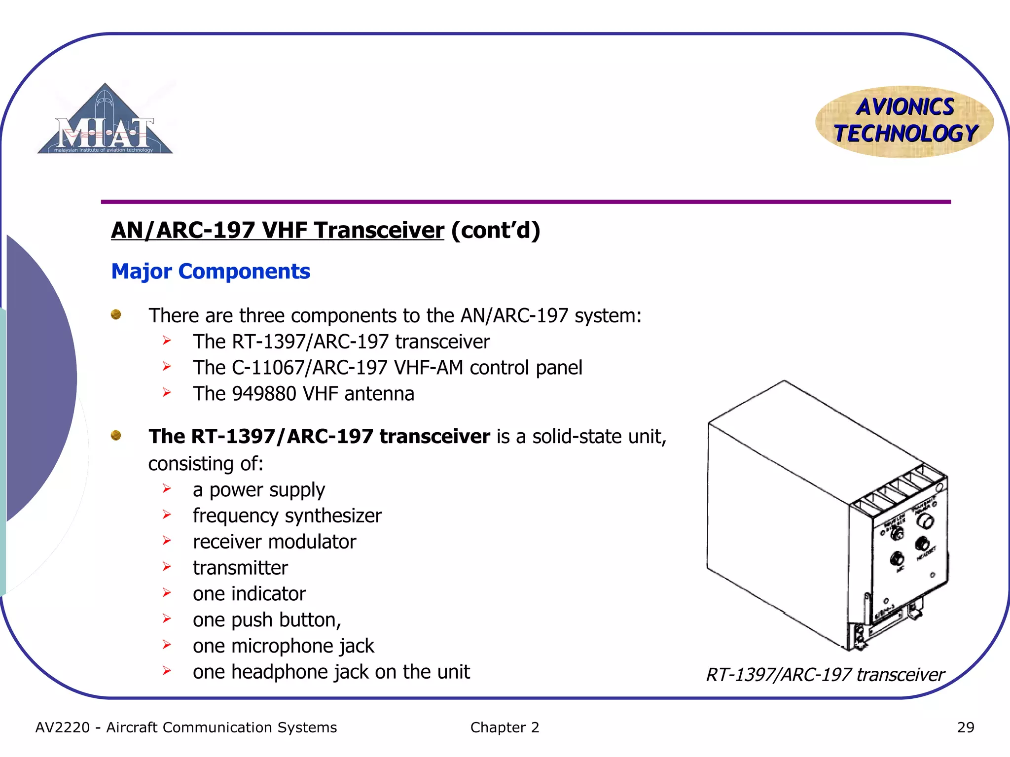
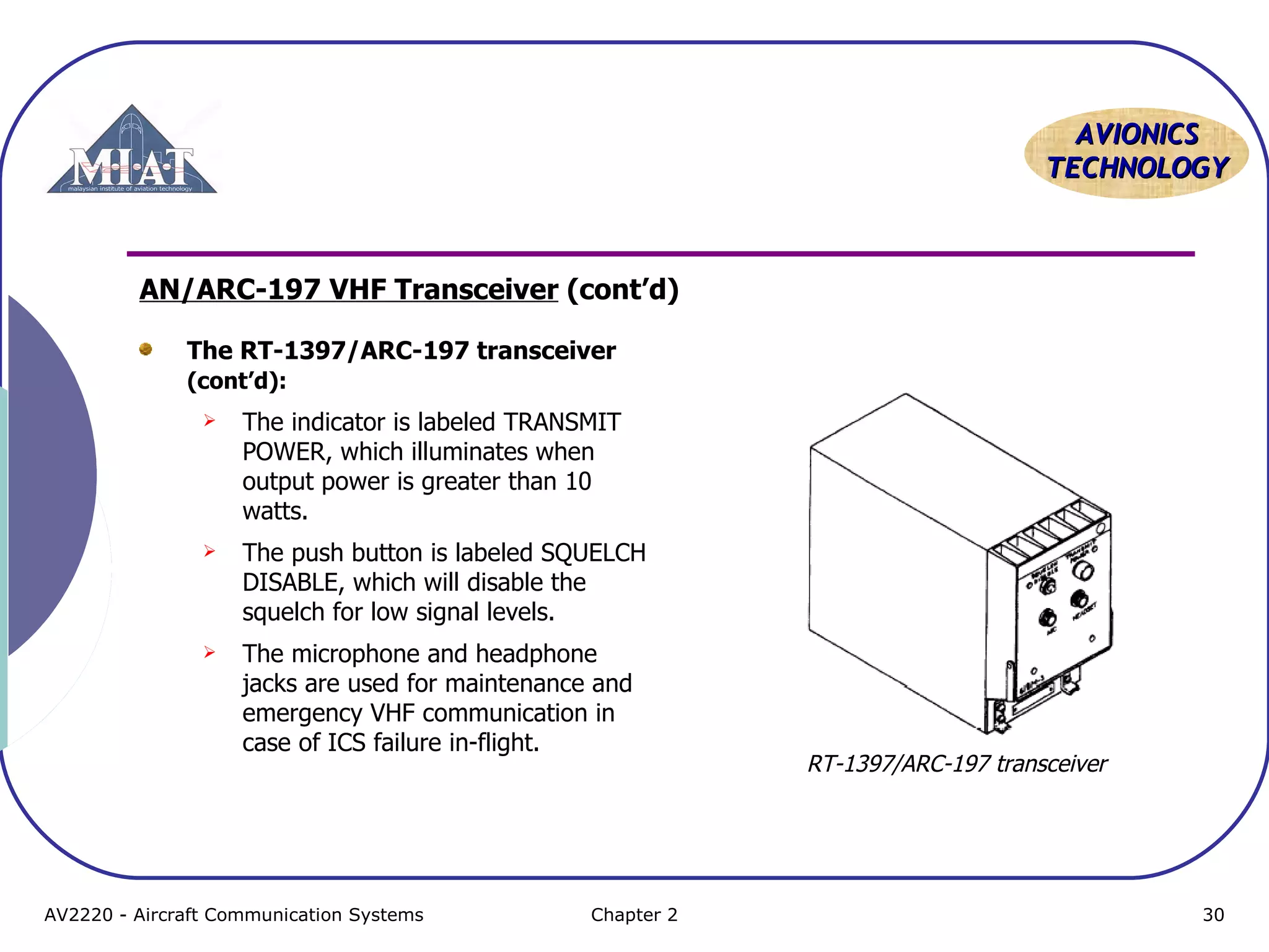
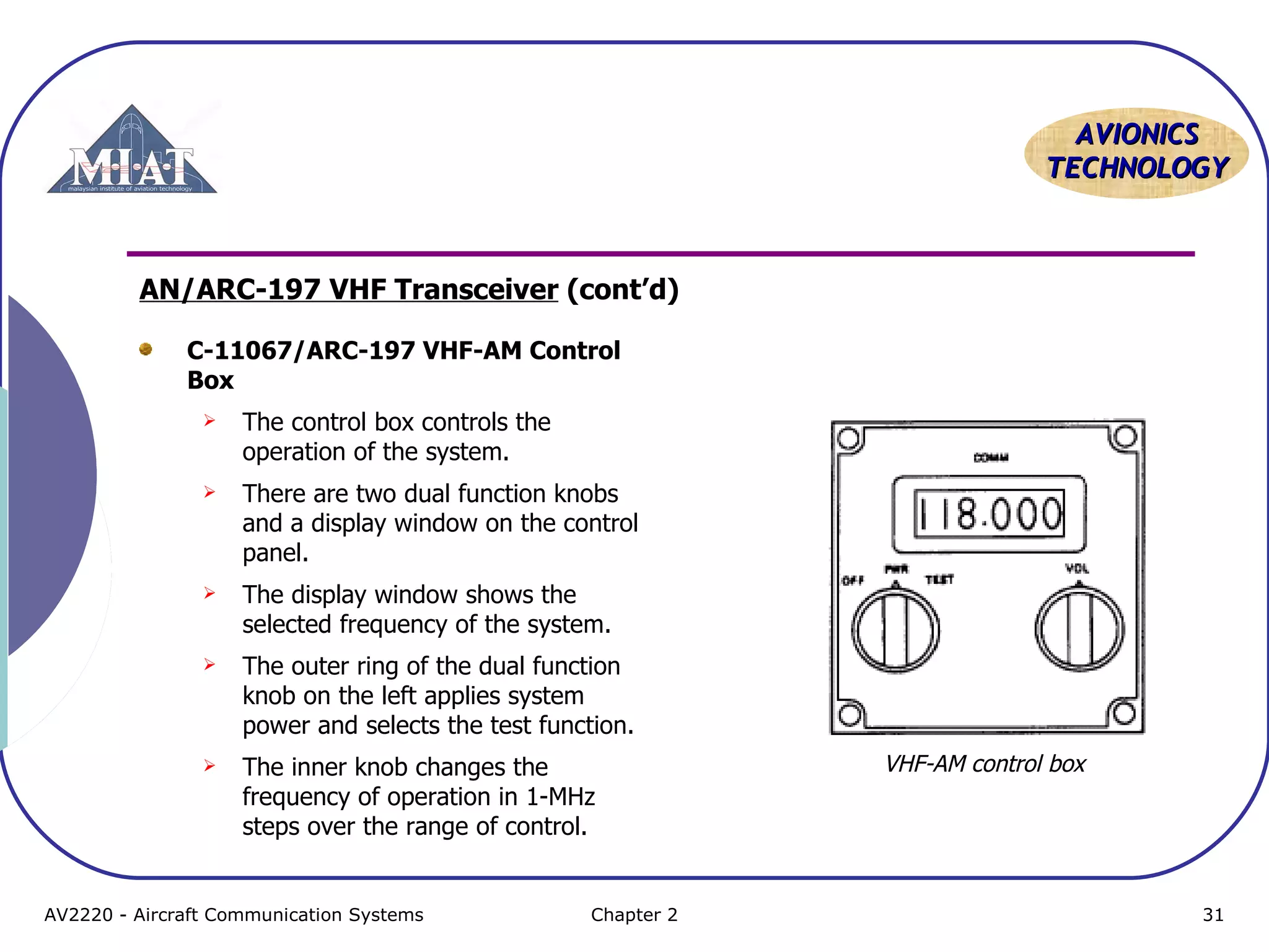
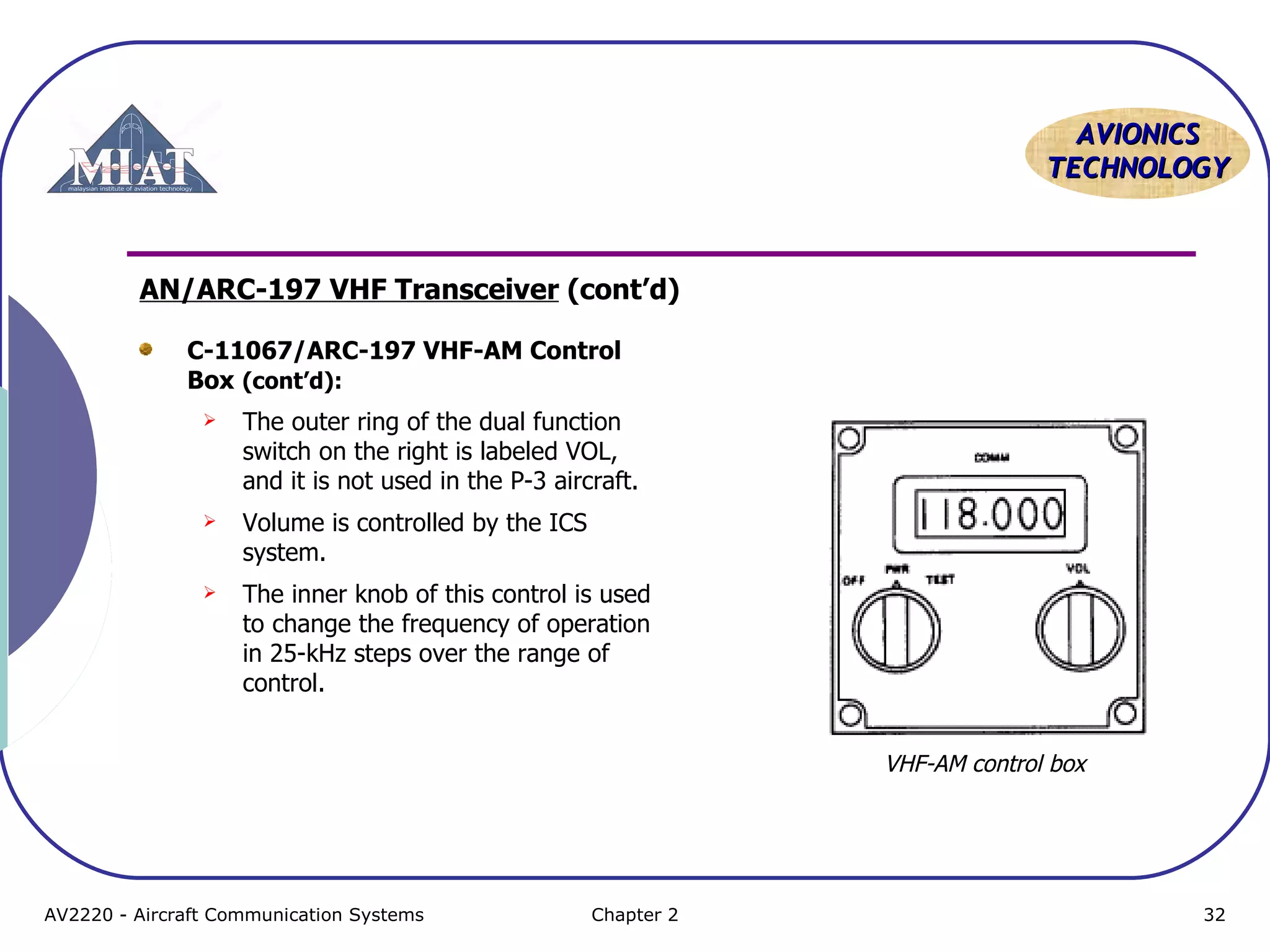
VHF System Description (cont’d)
Because of the nature of VHF radio signals, the average communicating -
distance from aircraft to ground is:
Approximately 30 mi [48 km] when the airplane is flying at 1000 ft [305 m]
Approximately 135 mi [217 km] when the airplane is at 10,000 ft [3048 m].
Transmitting frequency is determined by the position of the selector switches
on the VHF control panel.
The transmitter is tuned at the same time and to the same frequency as the
receiver.
The most modern VHF communication radios incorporate the latest digital
design features.
In general, the use of microprocessors and digital circuits has allowed for a 50
percent reduction in parts count and an 80 percent reduction in internal shop
adjustments as compared with the use of analog circuits.
AV2220 - Aircraft Communication Systems Chapter 2 5](https://image.slidesharecdn.com/topic4-vhfcommunicationsystem-141015155121-conversion-gate01/75/Aircraft-Communication-Topic-4-vhf-communication-system-5-2048.jpg)

VHF communication systems are used for air traffic control and allow pilots to communicate with air traffic control centers, towers, and flight service stations. They operate between 118-151.975 MHz and communication is limited to line-of-sight. Modern VHF systems incorporate digital technology for reduced size and easier maintenance. Pilots select frequencies using a control panel that interfaces with a transceiver unit, which contains a receiver, transmitter, and antenna to send and receive radio signals.