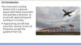
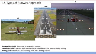
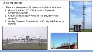
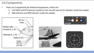
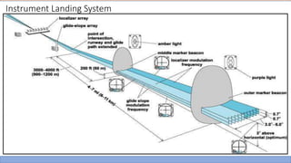
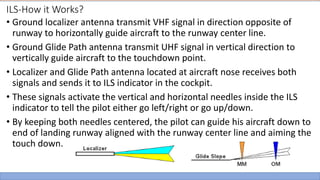
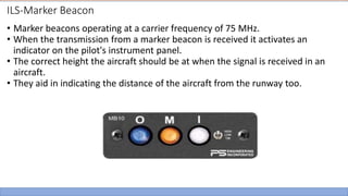
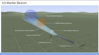
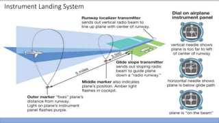
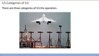
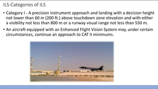
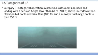
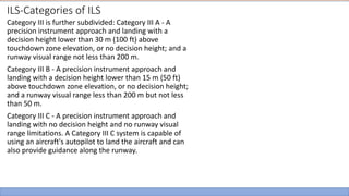
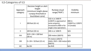
The document provides an overview of an Instrument Landing System (ILS). It discusses that an ILS uses radio beams to guide aircraft visually during low visibility conditions. It has three main components - localizer antennas that provide horizontal guidance to the runway centerline, glide slope antennas that provide vertical guidance to the ideal 3-degree glidepath, and marker beacons that indicate the aircraft's distance from the runway. The document also describes the ILS categories which differ based on minimum decision heights and visibility requirements for landing.
Instrument Landing System is a system installed in the aeroplanes for a safe landing. This slide includes all the necessary details about the system, components, installations, working, upgradations.
Airports Authority Of India:The Airports Authority of India (AAI) under the Ministry of Civil Aviation is responsible for creating, upgrading, maintaining and managing civil aviation infrastructure in India. It provides Air Traffic Management (ATM) services over Indian airspace and adjoining oceanic areas.
It manages a total of 125 airports, including 11 International Airports, 8 Custom Airports, 81 Domestic Airports and 25 Civil enclave at Military Airfields.
introduction:The Airports Authority of India provides air traffic services as per AAI Act 1995. These services are - air traffic control service, flight information service, and alerting service. In order to achieve the objectives of air traffic services there is a need to specify procedures necessary for the safety of air navigation for uniform application throughout India.
Instrumental Landing System - ILS - Airport EngineeringTheerumalai Ga
A short note on the Instrumental Landing system used for flight landing in Airport Engineering. Worked for an assignment. Hope it'll help you for a read to know about ILS
The Airport Surveillance Radar is a radar system used at airports to detect and display the position of aircraft in the terminal area. We have tried to analyse the basic setup of its operation used at every airport, the problems and challenges faced by the system and possible modifications in the technology.
A brief explanation about the importance of runway lighting and different types of runway lighting such as Approach Lighting, PAPi, APAPI, VASI, Runway edge, centre, end lighting
I am glad to be a part of the training at AAI Regional training center bhopal where got expose by tones of knowledge regarding the AAI and it's various departments specially CNS (communication, navigation & surveillance)...
All About Instrument Landing Systems AntennasGurleen Nayar
ILS antenna can be defined as a highly accurate and dependent means of runway navigation that provides both horizontal and vertical guidance for having a proper landing. It adopts a precision approach and provides adequate measures to conduct an excellent and professional landing.
Software Delivery At the Speed of AI: Inflectra Invests In AI-Powered QualityInflectra
In this insightful webinar, Inflectra explores how artificial intelligence (AI) is transforming software development and testing. Discover how AI-powered tools are revolutionizing every stage of the software development lifecycle (SDLC), from design and prototyping to testing, deployment, and monitoring.
Learn about:
• The Future of Testing: How AI is shifting testing towards verification, analysis, and higher-level skills, while reducing repetitive tasks.
• Test Automation: How AI-powered test case generation, optimization, and self-healing tests are making testing more efficient and effective.
• Visual Testing: Explore the emerging capabilities of AI in visual testing and how it's set to revolutionize UI verification.
• Inflectra's AI Solutions: See demonstrations of Inflectra's cutting-edge AI tools like the ChatGPT plugin and Azure Open AI platform, designed to streamline your testing process.
Whether you're a developer, tester, or QA professional, this webinar will give you valuable insights into how AI is shaping the future of software delivery.
Epistemic Interaction - tuning interfaces to provide information for AI supportAlan Dix
Paper presented at SYNERGY workshop at AVI 2024, Genoa, Italy. 3rd June 2024
https://alandix.com/academic/papers/synergy2024-epistemic/
As machine learning integrates deeper into human-computer interactions, the concept of epistemic interaction emerges, aiming to refine these interactions to enhance system adaptability. This approach encourages minor, intentional adjustments in user behaviour to enrich the data available for system learning. This paper introduces epistemic interaction within the context of human-system communication, illustrating how deliberate interaction design can improve system understanding and adaptation. Through concrete examples, we demonstrate the potential of epistemic interaction to significantly advance human-computer interaction by leveraging intuitive human communication strategies to inform system design and functionality, offering a novel pathway for enriching user-system engagements.
Search and Society: Reimagining Information Access for Radical FuturesBhaskar Mitra
The field of Information retrieval (IR) is currently undergoing a transformative shift, at least partly due to the emerging applications of generative AI to information access. In this talk, we will deliberate on the sociotechnical implications of generative AI for information access. We will argue that there is both a critical necessity and an exciting opportunity for the IR community to re-center our research agendas on societal needs while dismantling the artificial separation between the work on fairness, accountability, transparency, and ethics in IR and the rest of IR research. Instead of adopting a reactionary strategy of trying to mitigate potential social harms from emerging technologies, the community should aim to proactively set the research agenda for the kinds of systems we should build inspired by diverse explicitly stated sociotechnical imaginaries. The sociotechnical imaginaries that underpin the design and development of information access technologies needs to be explicitly articulated, and we need to develop theories of change in context of these diverse perspectives. Our guiding future imaginaries must be informed by other academic fields, such as democratic theory and critical theory, and should be co-developed with social science scholars, legal scholars, civil rights and social justice activists, and artists, among others.
Builder.ai Founder Sachin Dev Duggal's Strategic Approach to Create an Innova...Ramesh Iyer
In today's fast-changing business world, Companies that adapt and embrace new ideas often need help to keep up with the competition. However, fostering a culture of innovation takes much work. It takes vision, leadership and willingness to take risks in the right proportion. Sachin Dev Duggal, co-founder of Builder.ai, has perfected the art of this balance, creating a company culture where creativity and growth are nurtured at each stage.
GraphRAG is All You need? LLM & Knowledge GraphGuy Korland
Guy Korland, CEO and Co-founder of FalkorDB, will review two articles on the integration of language models with knowledge graphs.
1. Unifying Large Language Models and Knowledge Graphs: A Roadmap.
https://arxiv.org/abs/2306.08302
2. Microsoft Research's GraphRAG paper and a review paper on various uses of knowledge graphs:
https://www.microsoft.com/en-us/research/blog/graphrag-unlocking-llm-discovery-on-narrative-private-data/
Slack (or Teams) Automation for Bonterra Impact Management (fka Social Soluti...Jeffrey Haguewood
Sidekick Solutions uses Bonterra Impact Management (fka Social Solutions Apricot) and automation solutions to integrate data for business workflows.
We believe integration and automation are essential to user experience and the promise of efficient work through technology. Automation is the critical ingredient to realizing that full vision. We develop integration products and services for Bonterra Case Management software to support the deployment of automations for a variety of use cases.
This video focuses on the notifications, alerts, and approval requests using Slack for Bonterra Impact Management. The solutions covered in this webinar can also be deployed for Microsoft Teams.
Interested in deploying notification automations for Bonterra Impact Management? Contact us at sales@sidekicksolutionsllc.com to discuss next steps.
Essentials of Automations: Optimizing FME Workflows with ParametersSafe Software
Are you looking to streamline your workflows and boost your projects’ efficiency? Do you find yourself searching for ways to add flexibility and control over your FME workflows? If so, you’re in the right place.
Join us for an insightful dive into the world of FME parameters, a critical element in optimizing workflow efficiency. This webinar marks the beginning of our three-part “Essentials of Automation” series. This first webinar is designed to equip you with the knowledge and skills to utilize parameters effectively: enhancing the flexibility, maintainability, and user control of your FME projects.
Here’s what you’ll gain:
- Essentials of FME Parameters: Understand the pivotal role of parameters, including Reader/Writer, Transformer, User, and FME Flow categories. Discover how they are the key to unlocking automation and optimization within your workflows.
- Practical Applications in FME Form: Delve into key user parameter types including choice, connections, and file URLs. Allow users to control how a workflow runs, making your workflows more reusable. Learn to import values and deliver the best user experience for your workflows while enhancing accuracy.
- Optimization Strategies in FME Flow: Explore the creation and strategic deployment of parameters in FME Flow, including the use of deployment and geometry parameters, to maximize workflow efficiency.
- Pro Tips for Success: Gain insights on parameterizing connections and leveraging new features like Conditional Visibility for clarity and simplicity.
We’ll wrap up with a glimpse into future webinars, followed by a Q&A session to address your specific questions surrounding this topic.
Don’t miss this opportunity to elevate your FME expertise and drive your projects to new heights of efficiency.
Dev Dives: Train smarter, not harder – active learning and UiPath LLMs for do...UiPathCommunity
💥 Speed, accuracy, and scaling – discover the superpowers of GenAI in action with UiPath Document Understanding and Communications Mining™:
See how to accelerate model training and optimize model performance with active learning
Learn about the latest enhancements to out-of-the-box document processing – with little to no training required
Get an exclusive demo of the new family of UiPath LLMs – GenAI models specialized for processing different types of documents and messages
This is a hands-on session specifically designed for automation developers and AI enthusiasts seeking to enhance their knowledge in leveraging the latest intelligent document processing capabilities offered by UiPath.
Speakers:
👨🏫 Andras Palfi, Senior Product Manager, UiPath
👩🏫 Lenka Dulovicova, Product Program Manager, UiPath
2. ILS-Introduction
An Instrument Landing
System (ILS) is a ground-
based radio beam transmitter
that provides a direction to
an aircraft approaching and
landing on a runway.
Approaching aircraft that
tune their receiver to the ILS
frequency can get the
guidance from ILS.
3. ILS-Why do pilot need ILS?
• To enable safe landing during reduced visibility due to fog, rain, or snow.
• If an Aircraft is considerably ‘heavy’ for a runway length, guidance to the
exact ‘touch-down’ zone is required.
• In order to enable ‘Auto-land’ in newer aircrafts, ILS signals are essential.
4. ILS-History
• Tests of the first ILS began in 1929.
• The first scheduled passenger airliner to land using ILS was in 1938. A
Pennsylvania-Central Airlines Boeing 247-D.
• In 1949, ICAO adapted an ILS standard developed by the US Army as a
standard system for all of its member countries.
5. ILS-Types of Runway Approach
1.Non-Instrument Runway (NI): A runway intended for the operation of
aircraft using visual approach procedure
2. Instrument Runway: A runway intended for the operation of aircraft
using instrument approach procedures
a) Non-Precision Runway (NP): An instrument runway served by visual
aids and a non-visual aid providing at least lateral guidance adequate
for a straight-in approach
b) Precision Runway (P): Allow operations with a decision height and
visibility ILS Category 1, or II, or III.
6. ILS-Types of Runway Approach
Runway Threshold: Beginning of runway for landing.
Touchdown zone: The first point for the aircraft should touch the runway during landing.
Aiming point: serves as a visual aiming point for a landing aircraft.
NI
NP
P
8. ILS-Components
• There are 3 equipments for Ground Installations, which are:
1. Ground Localizer (LLZ, LOC) Antenna – To provide
horizontal navigation
2. Ground Glide path (GP) Antenna – To provide vertical
navigation
3. Marker Beacons – To provide aircraft’s height & distance to
Runway
9. ILS-Components
• There are 2 equipments for Airborne Equipments, which are:
1. LLZ (LOC) and GP antennas located on the aircraft nose & ILS indicator inside the cockpit.
2. MB antennas and MB Indicator inside the cockpit.
11. ILS-How it Works?
• Ground localizer antenna transmit VHF signal in direction opposite of
runway to horizontally guide aircraft to the runway center line.
• Ground Glide Path antenna transmit UHF signal in vertical direction to
vertically guide aircraft to the touchdown point.
• Localizer and Glide Path antenna located at aircraft nose receives both
signals and sends it to ILS indicator in the cockpit.
• These signals activate the vertical and horizontal needles inside the ILS
indicator to tell the pilot either go left/right or go up/down.
• By keeping both needles centered, the pilot can guide his aircraft down to
end of landing runway aligned with the runway center line and aiming the
touch down.
12. ILS-How LOC (LLZ) works?
• Localizer transmit two signals which overlap at the center.
• It operates in the VHF band: 108MHz to 117MHz
• The left side has a 90 Hz modulation and the right has a 150 Hz modulation.
• The overlap area provides the on-track signal.
• For example, if an aircraft approaching the runway center line from the right, it
will receive more of the 150 Hz modulation than 90Hz modulation.
• Difference in Depth of Modulation will align the aircraft with the runway
center line.
14. ILS-How LOC (LLZ) works?
Observe the yellow NAV vertical
pointer line tracking the runway
center line and moving towards right.
Airplane Approaching to the
left of runway center line.
15. ILS-How LOC works?
• Transmit two signals which overlap at the
center.
The left side has a 90 Hz & right has a 150 Hz
modulation.
The overlap area provides the on-track
signal.
16. ILS-How GS (GP) works?
• GS operates in UHF band: 329 to 335 MHz
• Glide path antenna produces two signals in the vertical
plane.
• The upper has a 90 Hz modulation and the bottom has a
150 Hz modulation.
• For example, if an aircraft approaching the runway too
high, it will receive more of the 90 Hz modulation than
150Hz modulation.
• Difference in Depth of Modulation will align the aircraft
with the 3o glide path.
18. ILS-How GS (GP) works?
Airplane Approaching above 3˚ glide path
Observe the yellow GS horizontal pointer
line tracking the 3˚ glide path and moving
downwards.
19. ILS-How GS (GP) works?
• Glide path produces two signals in the
vertical plane.
• The upper has a 90 Hz modulation and
the bottom has a 150 Hz modulation.
20. ILS-Marker Beacon
• Marker beacons operating at a carrier frequency of 75 MHz.
• When the transmission from a marker beacon is received it activates an
indicator on the pilot's instrument panel.
• The correct height the aircraft should be at when the signal is received in an
aircraft.
• They aid in indicating the distance of the aircraft from the runway too.
22. ILS-Outer Marker Beacon (OMB)
The outer marker is normally located 7.2 to 10 km from the runway threshold.
The cockpit indicator is a blue lamp that flashes in unison with the received
audio code. The purpose of this beacon is to provide height, distance, and
equipment functioning checks to aircraft on intermediate and final approach. On
the aircraft, the signal is received by a 75 MHz marker receiver. The pilot hears a
tone from the loudspeaker or headphones and a blue indicative bulb lights up.
23. ILS-MMB
The middle marker should be located so as to indicate, in low visibility
conditions, the missed approach point, and the point that visual contact with the
runway is imminent, ideally at a distance of approximately 1,100 m from the
threshold. The cockpit indicator is an amber lamp that flashes in unison with the
received audio code.
24. ILS-IMB
The inner marker will be located so as to indicate in low visibility conditions the
imminence of arrival at the runway threshold. This is typically the position of an
aircraft on the ILS as it reaches Category II minima. Ideally at a distance of
approximately 300 m from the threshold. The cockpit indicator is a white lamp
that flashes in unison with the received audio code.
27. ILS-Categories of ILS
• Category I - A precision instrument approach and landing with a decision height
not lower than 60 m (200 ft.) above touchdown zone elevation and with either
a visibility not less than 800 m or a runway visual range not less than 550 m.
• An aircraft equipped with an Enhanced Flight Vision System may, under certain
circumstances, continue an approach to CAT II minimums.
28. ILS-Categories of ILS
• Category II - Category II operation: A precision instrument approach and
landing with a decision height lower than 60 m (200 ft) above touchdown zone
elevation but not lower than 30 m (100 ft), and a runway visual range not less
than 350 m.
29. ILS-Categories of ILS
Category III is further subdivided: Category III A - A
precision instrument approach and landing with a
decision height lower than 30 m (100 ft) above
touchdown zone elevation, or no decision height; and a
runway visual range not less than 200 m.
Category III B - A precision instrument approach and
landing with a decision height lower than 15 m (50 ft)
above touchdown zone elevation, or no decision height;
and a runway visual range less than 200 m but not less
than 50 m.
Category III C - A precision instrument approach and
landing with no decision height and no runway visual
range limitations. A Category III C system is capable of
using an aircraft's autopilot to land the aircraft and can
also provide guidance along the runway.
30. Approach
category
Decision height or alert
height
(minimum height above
runway threshold or
touchdown zone)
Runway visual
range("RVR")
Visibility
minimum
I 200 feet (61 m)
550 m or 2400 ft
(1200 ft is approved at
some airports),
increased to 800 m for
single crew operations
800 m
(1600 ft or 1200 ft
in Canada)
II 100 feet (30 m) 300 m or 1000 ft N/A
IIIA
50 ft < DH < 100 feet
(30 m)
200 meters (660 ft) N/A
IIIB 0 < DH < 50 feet (15 m)
75 meters (246 ft)
(JAA)< RVR < 200 meters
(660 ft)
N/A
IIIC No DH No RVR N/A
ILS-Categories of ILS