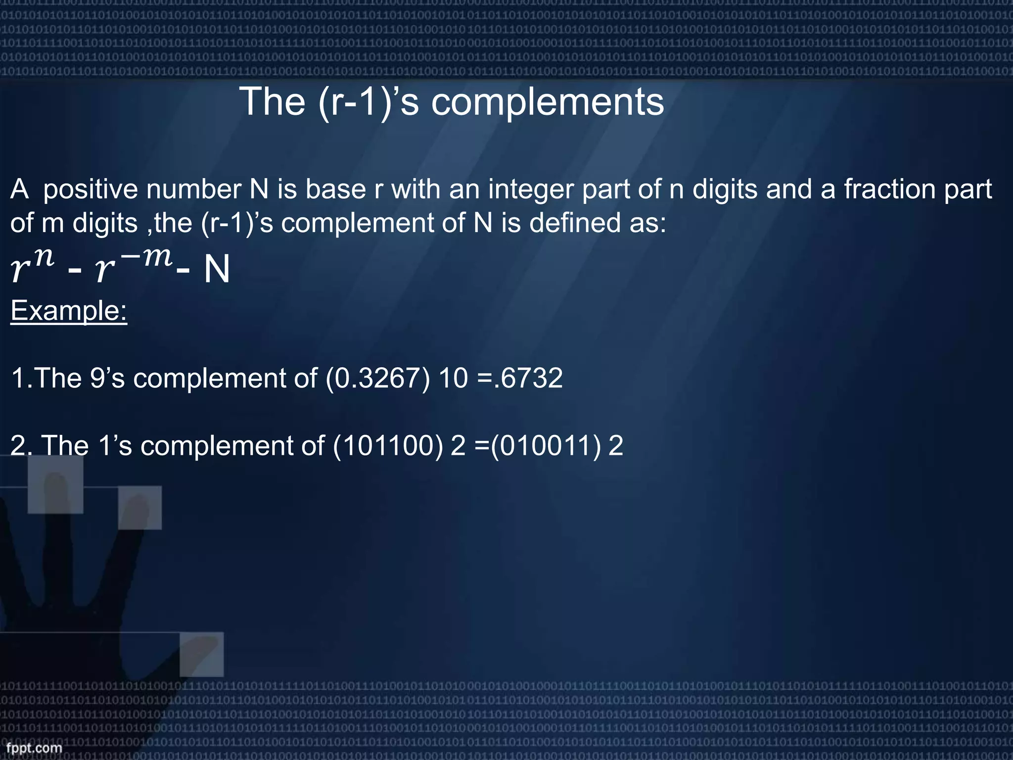
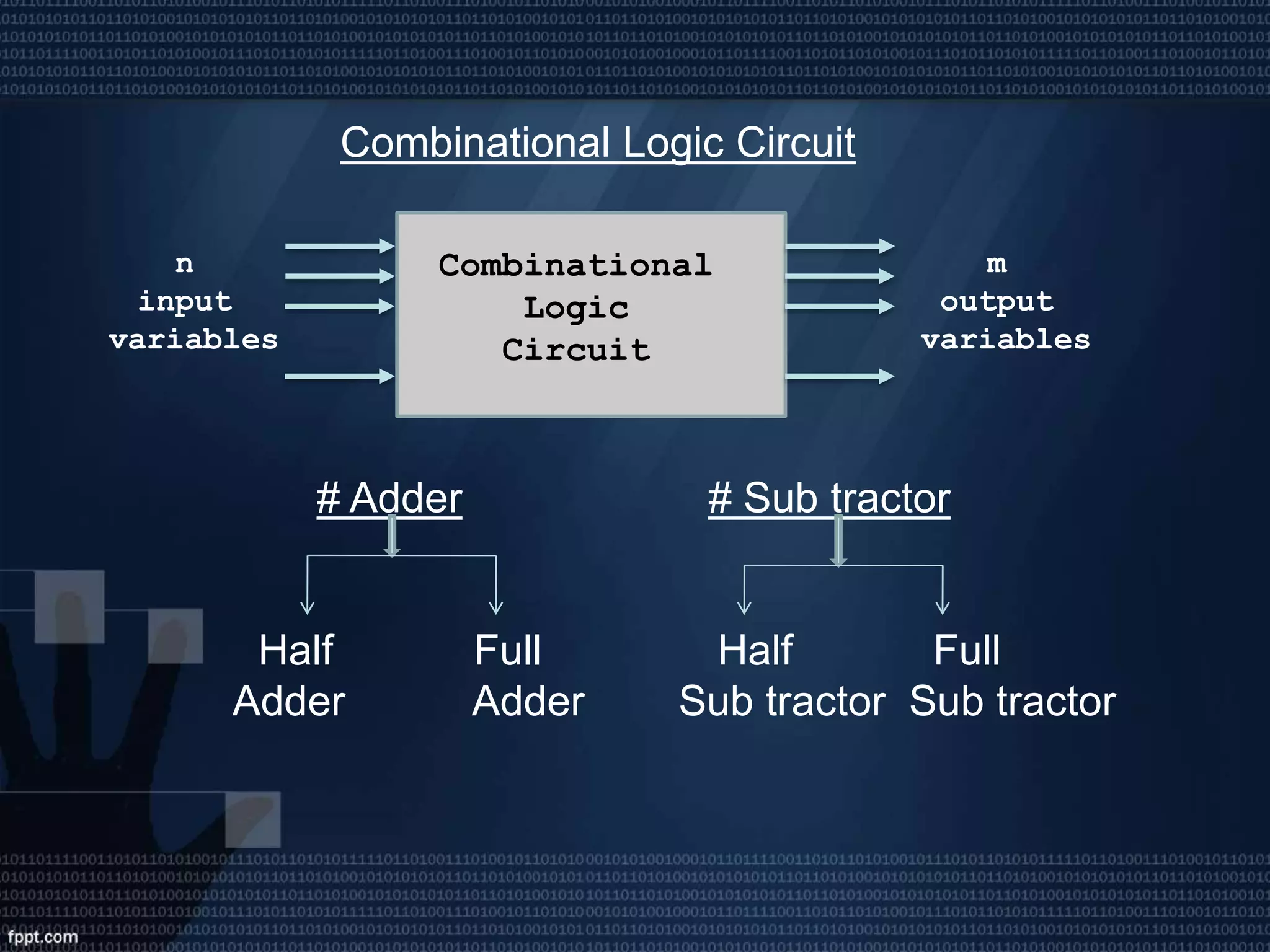
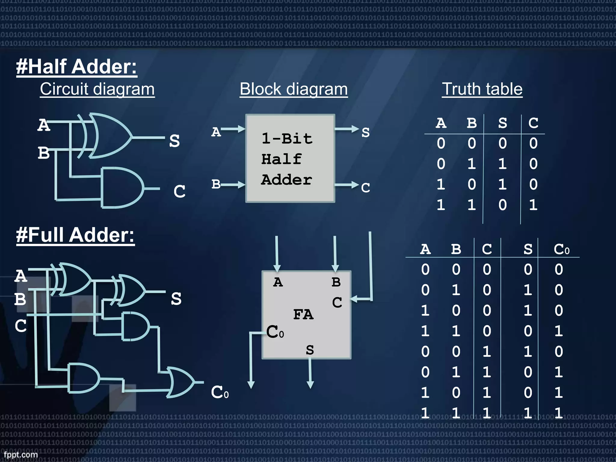
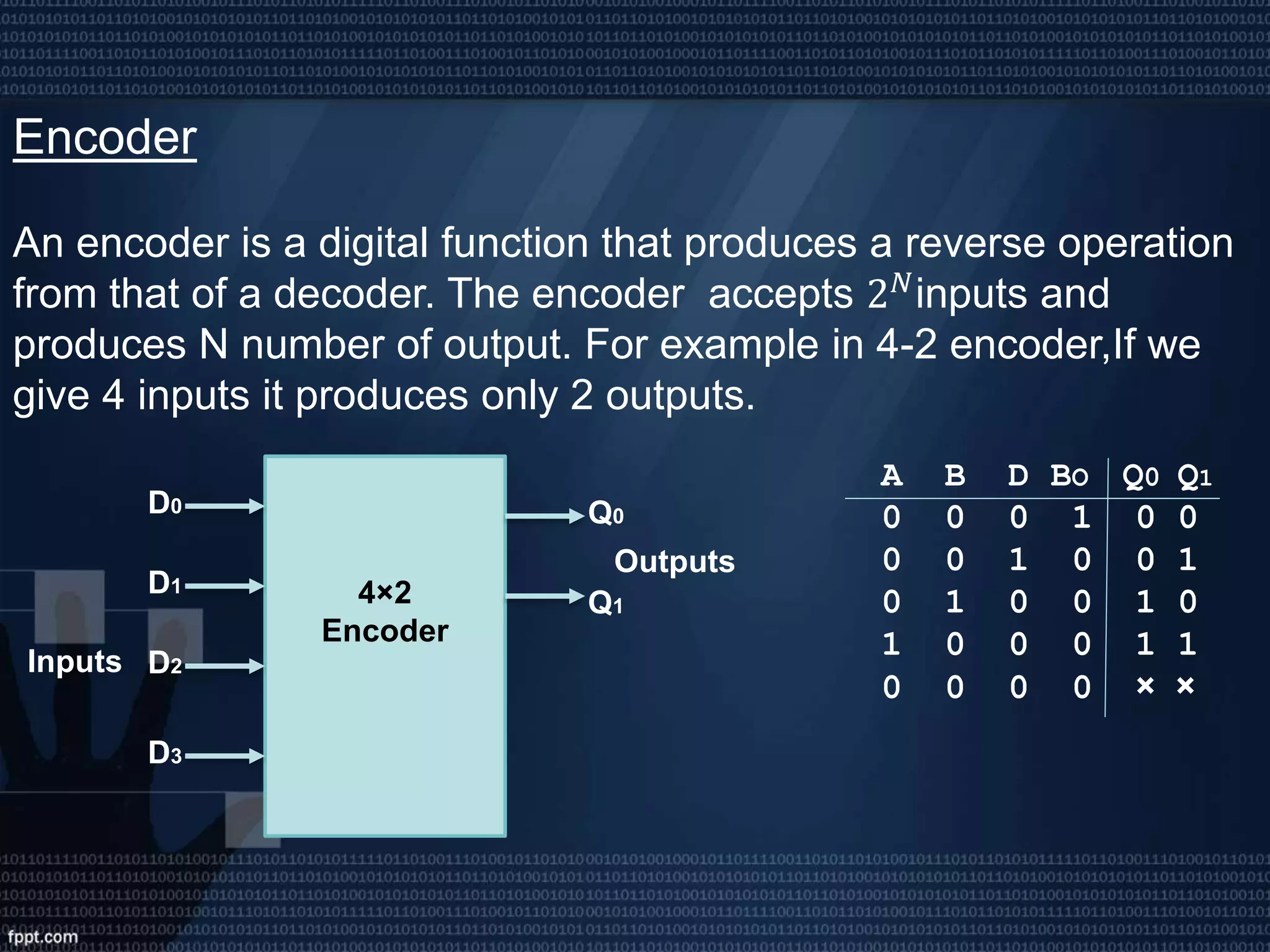
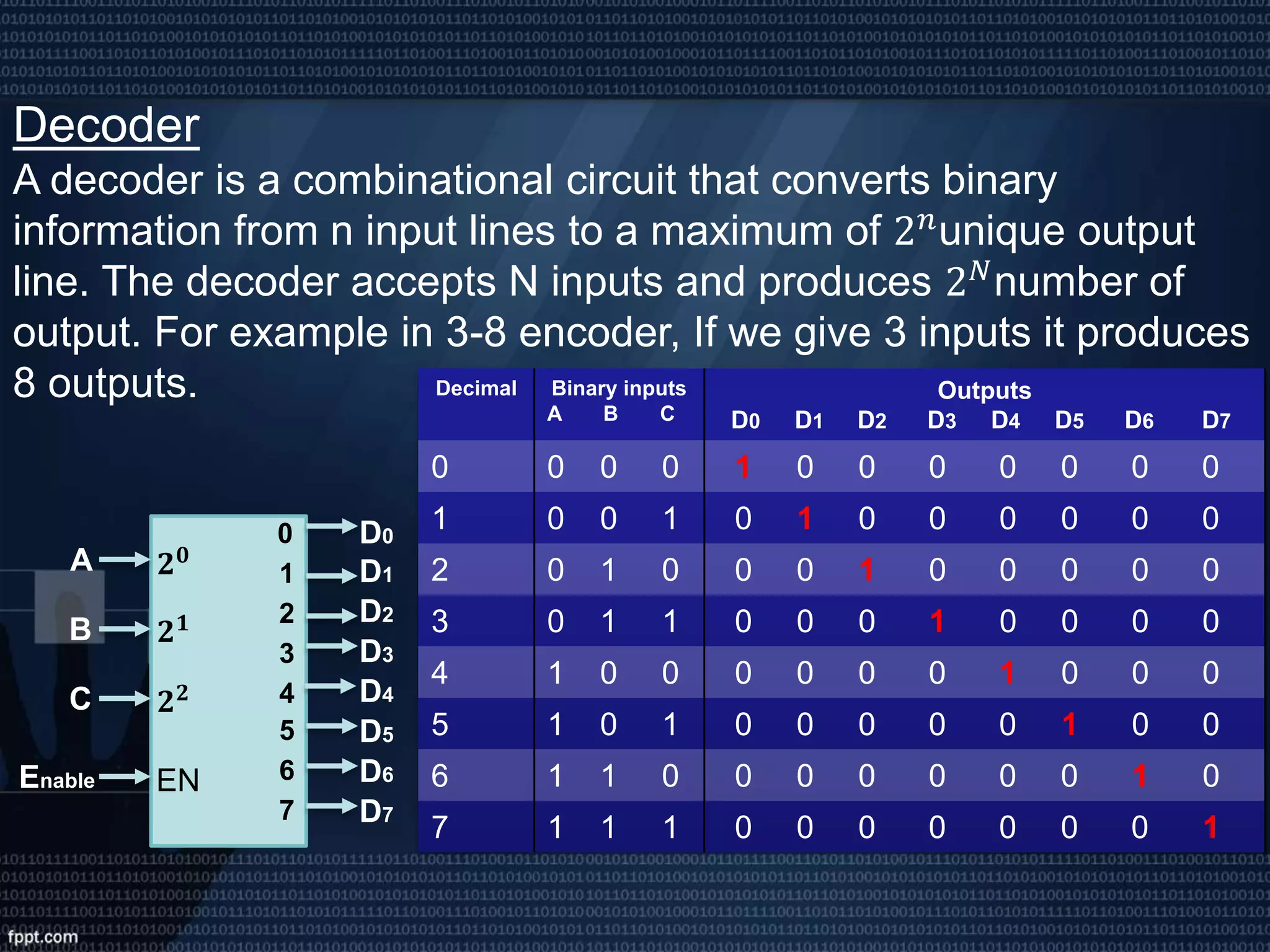
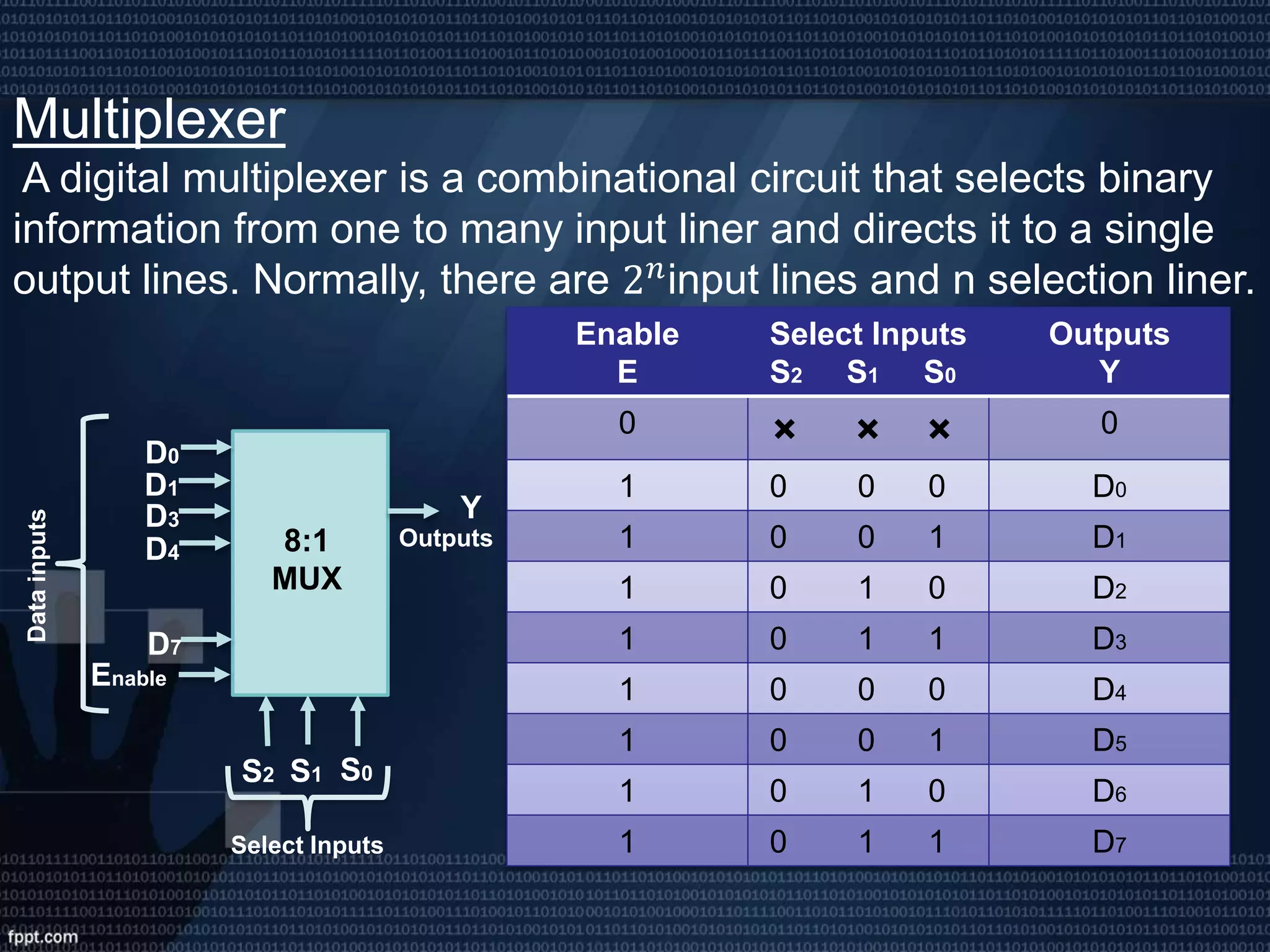
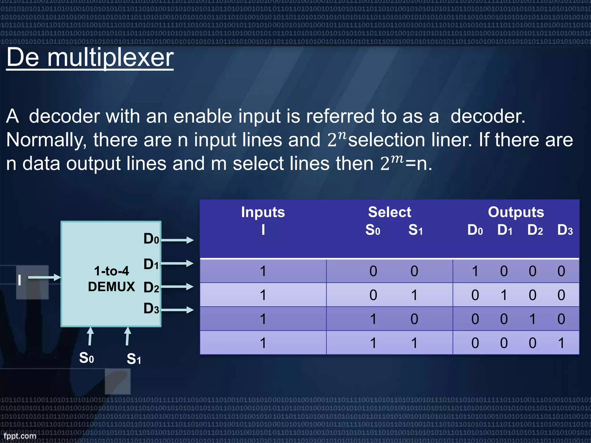
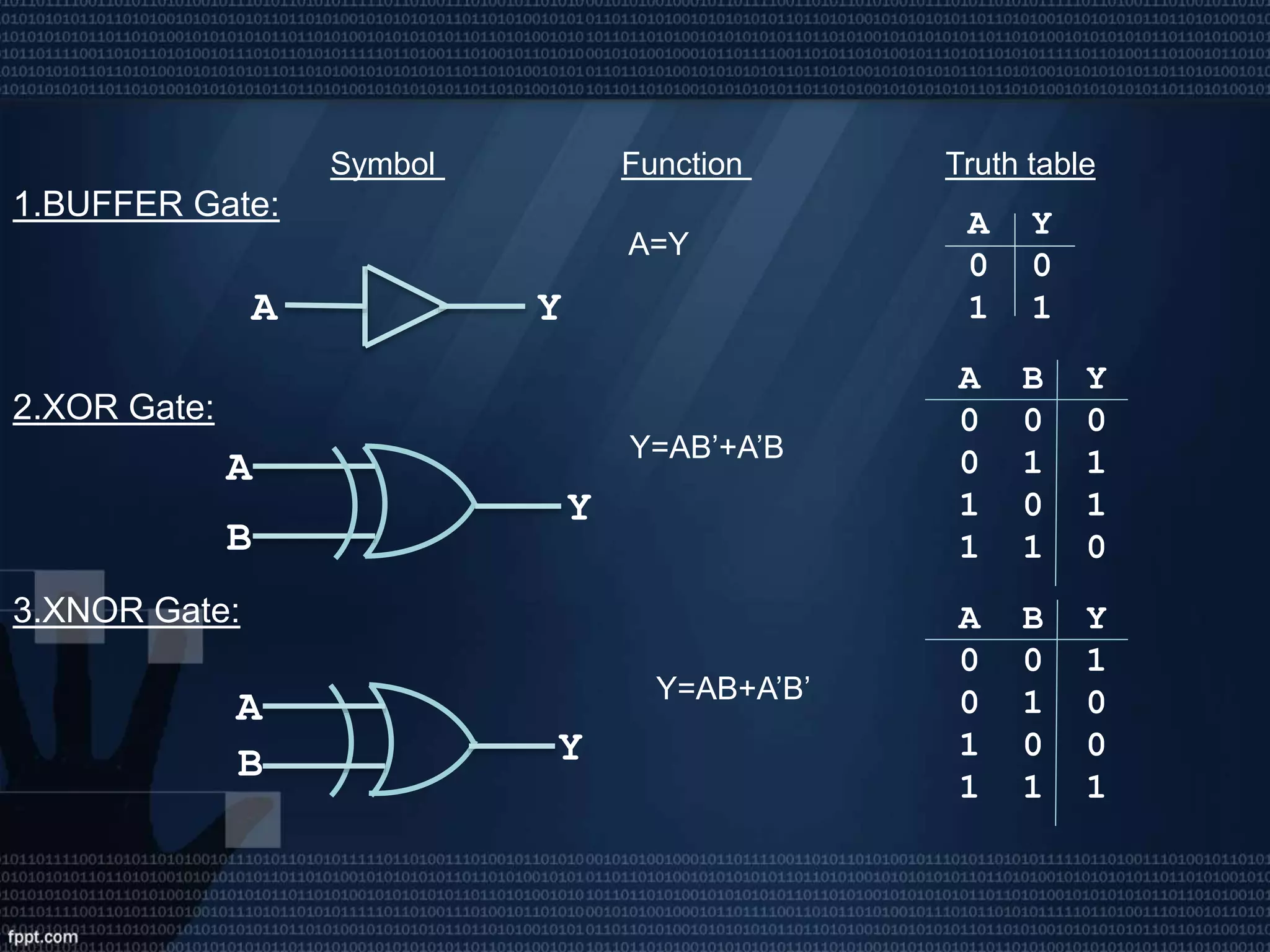
“Welcome To Our
Presentation”
Group Name: A
Group Members
Name ID
• Rafiqul Islam 152-33-2802
• Saurav Roy 152-33-2818
• Mehedi Hasan 152-33-2808
• Raysul Islam Tuhin 152-33-2807
• Tahmina Akter Jui 152-33-2831
Presentation Topic:
• Complement
• Combinational Logic Circuit
• Encoder/Decoder
• Multiplexer/De multiplexer
• Logic Gate
Complements
# Complements are used in digital computer for simplifying the subtraction
operation and for logical manipulations.
# There are two types of complements
1.The r’s complements
2.The (r-1)’s complements
2’s and 1’s complement for binary number
10’s and 9’s complement for decimal number
The r’s complements
A positive number N is base r with an integer part of n digits, the r’s
complement of N is defined as:
𝑟 𝑛
- N
Example:
1.The 10’s complement of (52520) 10 =47180
2. The 2’s complement of (101100) 2 =(10100)2
The (r-1)’s complements
A positive number N is base r with an integer part of n digits and a fraction part
of m digits ,the (r-1)’s complement of N is defined as:
𝑟 𝑛
- 𝑟−𝑚
- N
Example:
1.The 9’s complement of (0.3267) 10 =.6732
2. The 1’s complement of (101100) 2 =(010011) 2
Combinational Logic Circuit
# Adder # Sub tractor
Half Full Half Full
Adder Adder Sub tractor Sub tractor
n
input
variables
m
output
variables
Combinational
Logic
Circuit
A
B
S
C
A B S C
0 0 0 0
0 1 1 0
1 0 1 0
1 1 0 1
A S1-Bit
Half
AdderB C
A
B S
C
C0
#Half Adder:
Circuit diagram Block diagram Truth table
#Full Adder:
A
S
FA
B
C
C0
A B C S C0
0 0 0 0 0
0 1 0 1 0
1 0 0 1 0
1 1 0 0 1
0 0 1 1 0
0 1 1 0 1
1 0 1 0 1
1 1 1 1 1
#Half Sub tractor :
Circuit diagram Block diagram Truth table
#Full Sub tractor :
A
B
D
BO
A D
Half
Subtractor
B BO
A B D BO
0 0 0 0
0 1 1 1
1 0 1 0
1 1 0 0
A B Bi D B0
0 0 0 0 0
0 0 1 1 1
0 1 0 1 1
0 1 1 0 1
1 0 0 1 0
1 0 1 0 0
1 1 0 0 0
1 1 1 1 1
A D
Full
SubtractorB
BOBi
A
B D
BO
Bi
Encoder
An encoder is a digital function that produces a reverse operation
from that of a decoder. The encoder accepts 2 𝑁inputs and
produces N number of output. For example in 4-2 encoder,If we
give 4 inputs it produces only 2 outputs.
D3
D0
D1
D2
Q0
Q14×2
Encoder
Inputs
Outputs
A B D BO Q0 Q1
0 0 0 1 0 0
0 0 1 0 0 1
0 1 0 0 1 0
1 0 0 0 1 1
0 0 0 0 × ×
Decoder
A decoder is a combinational circuit that converts binary
information from n input lines to a maximum of 2 𝑛unique output
line. The decoder accepts N inputs and produces 2 𝑁
number of
output. For example in 3-8 encoder, If we give 3 inputs it produces
8 outputs.
Enable
A
B
C
D0
𝟐 𝟎
D7
D6
D1
D2
D3
D5
D4
0
𝟐 𝟏
𝟐 𝟐
EN
1
2
3
4
5
6
7
Decimal Binary inputs
A B C
Outputs
D0 D1 D2 D3 D4 D5 D6 D7
0 0 0 0 1 0 0 0 0 0 0 0
1 0 0 1 0 1 0 0 0 0 0 0
2 0 1 0 0 0 1 0 0 0 0 0
3 0 1 1 0 0 0 1 0 0 0 0
4 1 0 0 0 0 0 0 1 0 0 0
5 1 0 1 0 0 0 0 0 1 0 0
6 1 1 0 0 0 0 0 0 0 1 0
7 1 1 1 0 0 0 0 0 0 0 1
Multiplexer
A digital multiplexer is a combinational circuit that selects binary
information from one to many input liner and directs it to a single
output lines. Normally, there are 2 𝑛input lines and n selection liner.
S0
Enable
S2
8:1
MUX
S1
D0
D7
D1
YD3
D4
Datainputs
Select Inputs
Outputs
Enable
E
Select Inputs
S2 S1 S0
Outputs
Y
0 × × × 0
1 0 0 0 D0
1 0 0 1 D1
1 0 1 0 D2
1 0 1 1 D3
1 0 0 0 D4
1 0 0 1 D5
1 0 1 0 D6
1 0 1 1 D7
De multiplexer
A decoder with an enable input is referred to as a decoder.
Normally, there are n input lines and 2 𝑛selection liner. If there are
n data output lines and m select lines then 2 𝑚
=n.
I
S0
D0
D1
D2
D3
1-to-4
DEMUX
S1
Inputs
I
Select
S0 S1
Outputs
D0 D1 D2 D3
1 0 0 1 0 0 0
1 0 1 0 1 0 0
1 1 0 0 0 1 0
1 1 1 0 0 0 1
Logic Gate
*A large number of electronic circuits are made up of logic gates. These process signals
which represent true or false.
*There are Three types of basic gate:
Symbol Function Truth table
1.AND Gate:
Y=A.B
2.OR Gate:
Y=A+B
3.NOT Gate:
Y=A’
X Y Z
0 0 0
0 1 0
1 0 0
1 1 1
A
B
Y
X Y Z
0 0 0
0 1 1
1 0 1
1 1 1
X 𝑿′
0 1
1 0
A
B
Y
YA
*There are two types of Universal logic gate:
Symbol Function Truth table
1.NAND Gate:
Y= (A.B)’
2.NOR Gate:
Y= (A+B)’
A
B
Y
A
B
Y
A B Y
0 0 1
0 1 1
1 0 1
1 1 0
A B Y
0 0 1
0 1 0
1 0 0
1 1 0
Symbol Function Truth table
1.BUFFER Gate:
A=Y
2.XOR Gate:
Y=AB’+A’B
3.XNOR Gate:
Y=AB+A’B’
A Y
0 0
1 1A Y
A
B
Y
A B Y
0 0 0
0 1 1
1 0 1
1 1 0
A
B Y
A B Y
0 0 1
0 1 0
1 0 0
1 1 1
digital electronics..

digital electronics..

  • 1.
  • 2.
    Group Name: A GroupMembers Name ID • Rafiqul Islam 152-33-2802 • Saurav Roy 152-33-2818 • Mehedi Hasan 152-33-2808 • Raysul Islam Tuhin 152-33-2807 • Tahmina Akter Jui 152-33-2831
  • 3.
    Presentation Topic: • Complement •Combinational Logic Circuit • Encoder/Decoder • Multiplexer/De multiplexer • Logic Gate
  • 4.
    Complements # Complements areused in digital computer for simplifying the subtraction operation and for logical manipulations. # There are two types of complements 1.The r’s complements 2.The (r-1)’s complements 2’s and 1’s complement for binary number 10’s and 9’s complement for decimal number
  • 5.
    The r’s complements Apositive number N is base r with an integer part of n digits, the r’s complement of N is defined as: 𝑟 𝑛 - N Example: 1.The 10’s complement of (52520) 10 =47180 2. The 2’s complement of (101100) 2 =(10100)2
  • 6.
    The (r-1)’s complements Apositive number N is base r with an integer part of n digits and a fraction part of m digits ,the (r-1)’s complement of N is defined as: 𝑟 𝑛 - 𝑟−𝑚 - N Example: 1.The 9’s complement of (0.3267) 10 =.6732 2. The 1’s complement of (101100) 2 =(010011) 2
  • 7.
    Combinational Logic Circuit #Adder # Sub tractor Half Full Half Full Adder Adder Sub tractor Sub tractor n input variables m output variables Combinational Logic Circuit
  • 8.
    A B S C A B SC 0 0 0 0 0 1 1 0 1 0 1 0 1 1 0 1 A S1-Bit Half AdderB C A B S C C0 #Half Adder: Circuit diagram Block diagram Truth table #Full Adder: A S FA B C C0 A B C S C0 0 0 0 0 0 0 1 0 1 0 1 0 0 1 0 1 1 0 0 1 0 0 1 1 0 0 1 1 0 1 1 0 1 0 1 1 1 1 1 1
  • 9.
    #Half Sub tractor: Circuit diagram Block diagram Truth table #Full Sub tractor : A B D BO A D Half Subtractor B BO A B D BO 0 0 0 0 0 1 1 1 1 0 1 0 1 1 0 0 A B Bi D B0 0 0 0 0 0 0 0 1 1 1 0 1 0 1 1 0 1 1 0 1 1 0 0 1 0 1 0 1 0 0 1 1 0 0 0 1 1 1 1 1 A D Full SubtractorB BOBi A B D BO Bi
  • 10.
    Encoder An encoder isa digital function that produces a reverse operation from that of a decoder. The encoder accepts 2 𝑁inputs and produces N number of output. For example in 4-2 encoder,If we give 4 inputs it produces only 2 outputs. D3 D0 D1 D2 Q0 Q14×2 Encoder Inputs Outputs A B D BO Q0 Q1 0 0 0 1 0 0 0 0 1 0 0 1 0 1 0 0 1 0 1 0 0 0 1 1 0 0 0 0 × ×
  • 11.
    Decoder A decoder isa combinational circuit that converts binary information from n input lines to a maximum of 2 𝑛unique output line. The decoder accepts N inputs and produces 2 𝑁 number of output. For example in 3-8 encoder, If we give 3 inputs it produces 8 outputs. Enable A B C D0 𝟐 𝟎 D7 D6 D1 D2 D3 D5 D4 0 𝟐 𝟏 𝟐 𝟐 EN 1 2 3 4 5 6 7 Decimal Binary inputs A B C Outputs D0 D1 D2 D3 D4 D5 D6 D7 0 0 0 0 1 0 0 0 0 0 0 0 1 0 0 1 0 1 0 0 0 0 0 0 2 0 1 0 0 0 1 0 0 0 0 0 3 0 1 1 0 0 0 1 0 0 0 0 4 1 0 0 0 0 0 0 1 0 0 0 5 1 0 1 0 0 0 0 0 1 0 0 6 1 1 0 0 0 0 0 0 0 1 0 7 1 1 1 0 0 0 0 0 0 0 1
  • 12.
    Multiplexer A digital multiplexeris a combinational circuit that selects binary information from one to many input liner and directs it to a single output lines. Normally, there are 2 𝑛input lines and n selection liner. S0 Enable S2 8:1 MUX S1 D0 D7 D1 YD3 D4 Datainputs Select Inputs Outputs Enable E Select Inputs S2 S1 S0 Outputs Y 0 × × × 0 1 0 0 0 D0 1 0 0 1 D1 1 0 1 0 D2 1 0 1 1 D3 1 0 0 0 D4 1 0 0 1 D5 1 0 1 0 D6 1 0 1 1 D7
  • 13.
    De multiplexer A decoderwith an enable input is referred to as a decoder. Normally, there are n input lines and 2 𝑛selection liner. If there are n data output lines and m select lines then 2 𝑚 =n. I S0 D0 D1 D2 D3 1-to-4 DEMUX S1 Inputs I Select S0 S1 Outputs D0 D1 D2 D3 1 0 0 1 0 0 0 1 0 1 0 1 0 0 1 1 0 0 0 1 0 1 1 1 0 0 0 1
  • 14.
    Logic Gate *A largenumber of electronic circuits are made up of logic gates. These process signals which represent true or false. *There are Three types of basic gate: Symbol Function Truth table 1.AND Gate: Y=A.B 2.OR Gate: Y=A+B 3.NOT Gate: Y=A’ X Y Z 0 0 0 0 1 0 1 0 0 1 1 1 A B Y X Y Z 0 0 0 0 1 1 1 0 1 1 1 1 X 𝑿′ 0 1 1 0 A B Y YA
  • 15.
    *There are twotypes of Universal logic gate: Symbol Function Truth table 1.NAND Gate: Y= (A.B)’ 2.NOR Gate: Y= (A+B)’ A B Y A B Y A B Y 0 0 1 0 1 1 1 0 1 1 1 0 A B Y 0 0 1 0 1 0 1 0 0 1 1 0
  • 16.
    Symbol Function Truthtable 1.BUFFER Gate: A=Y 2.XOR Gate: Y=AB’+A’B 3.XNOR Gate: Y=AB+A’B’ A Y 0 0 1 1A Y A B Y A B Y 0 0 0 0 1 1 1 0 1 1 1 0 A B Y A B Y 0 0 1 0 1 0 1 0 0 1 1 1