Download as PDF, PPTX
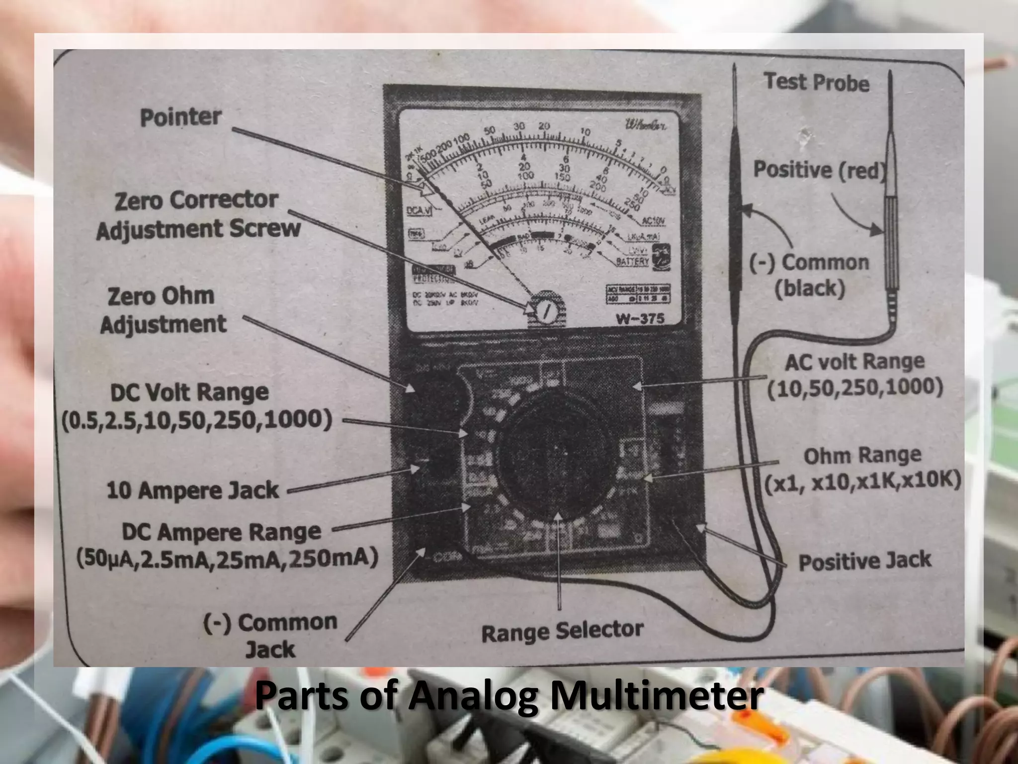
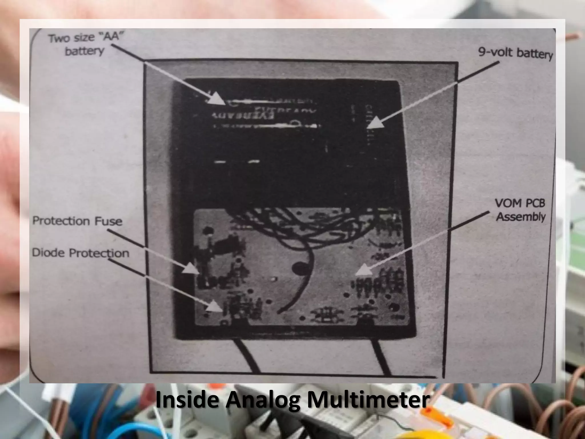
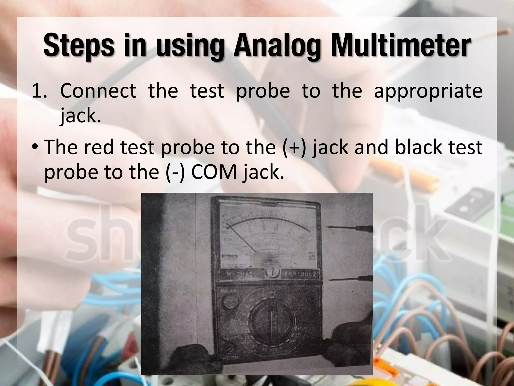
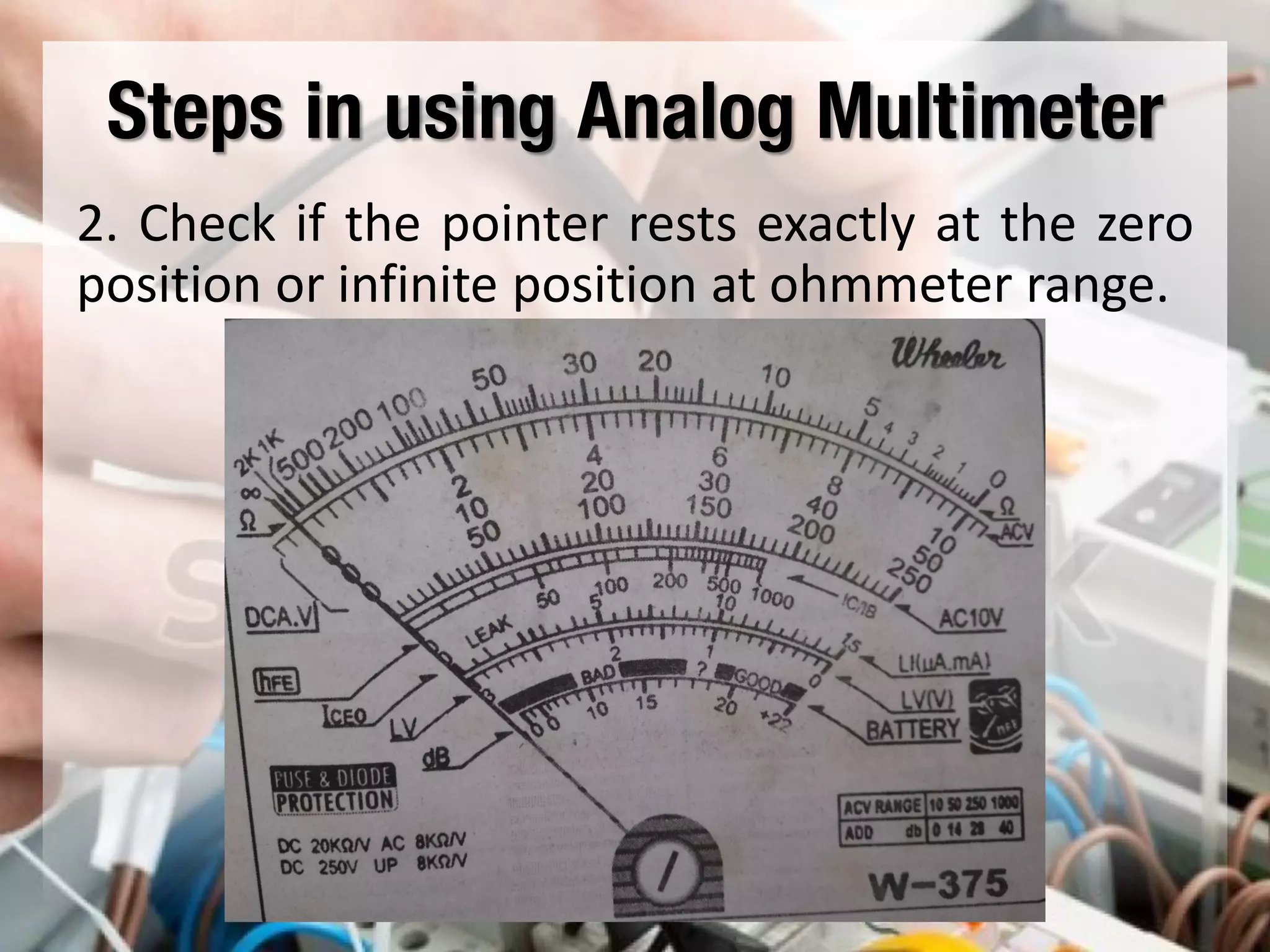
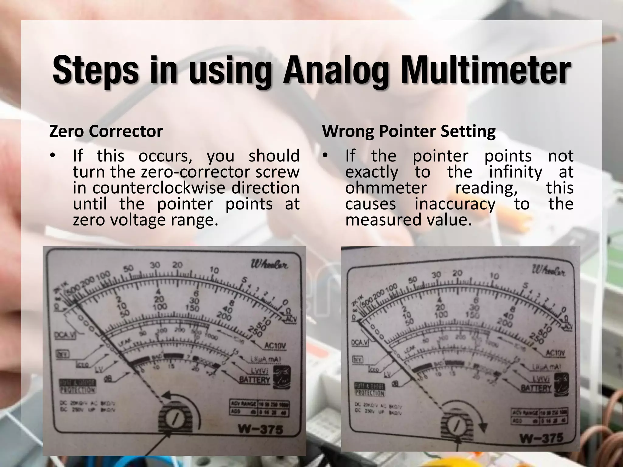
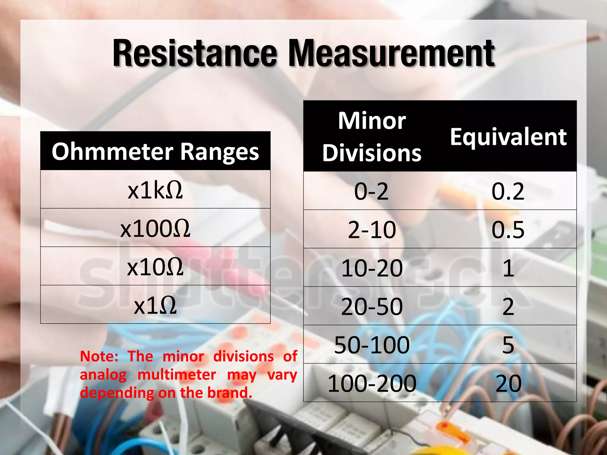
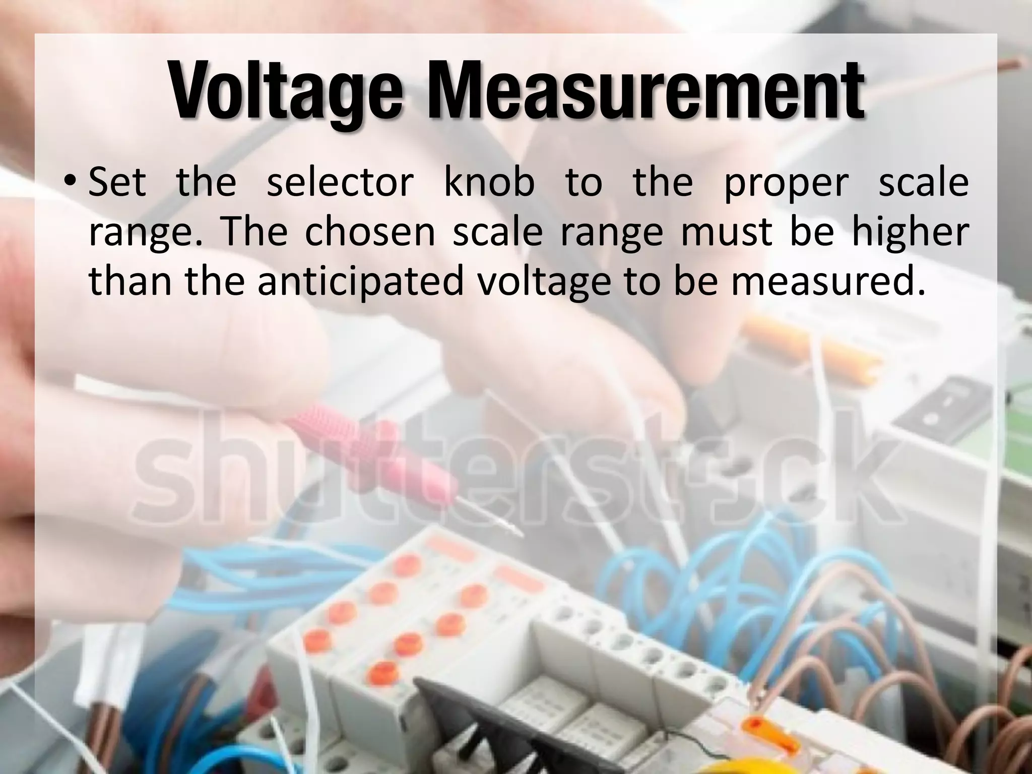
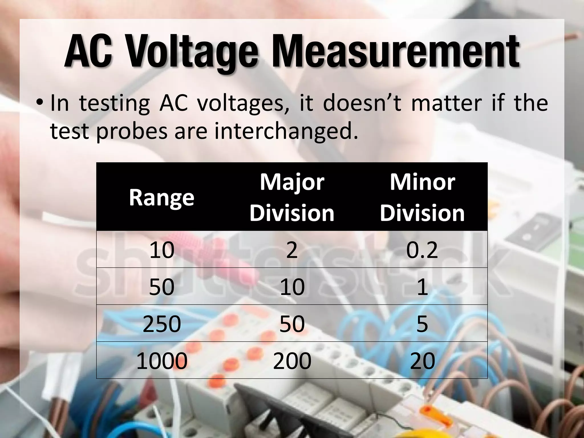
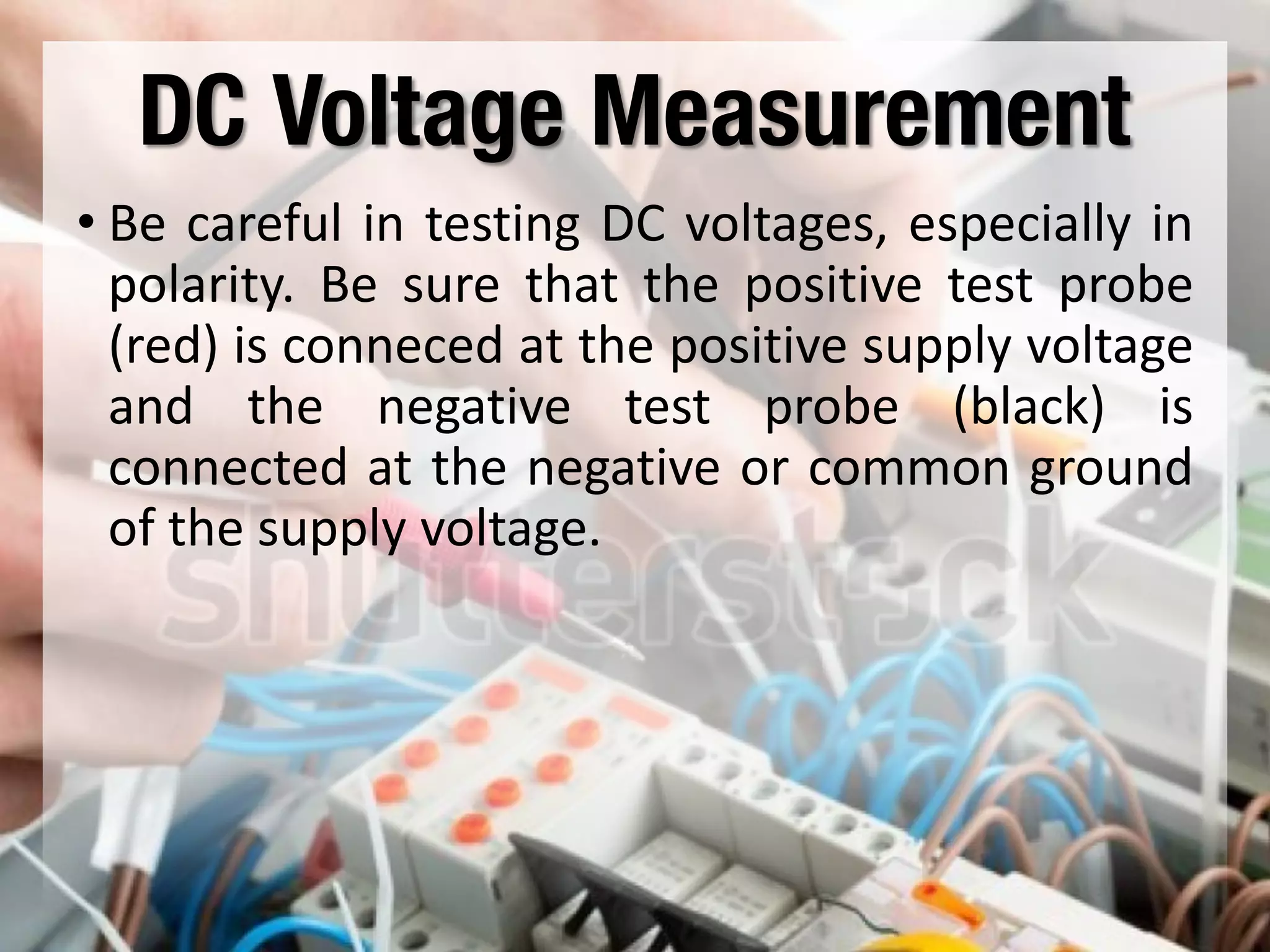


This document provides instructions on how to use an analog multimeter. It begins by listing the lesson objectives, which are to identify the parts of an analog multimeter, perform measurements and calculations in electronics, and appreciate the importance of practical skills. It then describes the key features of an analog multimeter, including that it uses a moving coil assembly and needle pointer. The document outlines the main parts of an analog multimeter and provides step-by-step instructions on how to use one to measure resistance, voltage, and current. It includes details on properly connecting probes and selecting ranges.


