Combinational Circuits
Outputat a specified time is a function of the inputs at that time.
Output depends purely upon PRESENT input, therefore it
doesn’t require memory to store past inputs.
The various circuits are
Multiplexer/ Demultiplexer
Decoder/ Encoder
Adder
2.
Multiplexers
Multiplex meansmany into one.
An N-to-1 multiplexer receives information from N input
lines and transmits information to a single line.
3.
Multiplexer
It isa combinational circuit that selects binary
information from one of the input lines and directs it to a
single output line
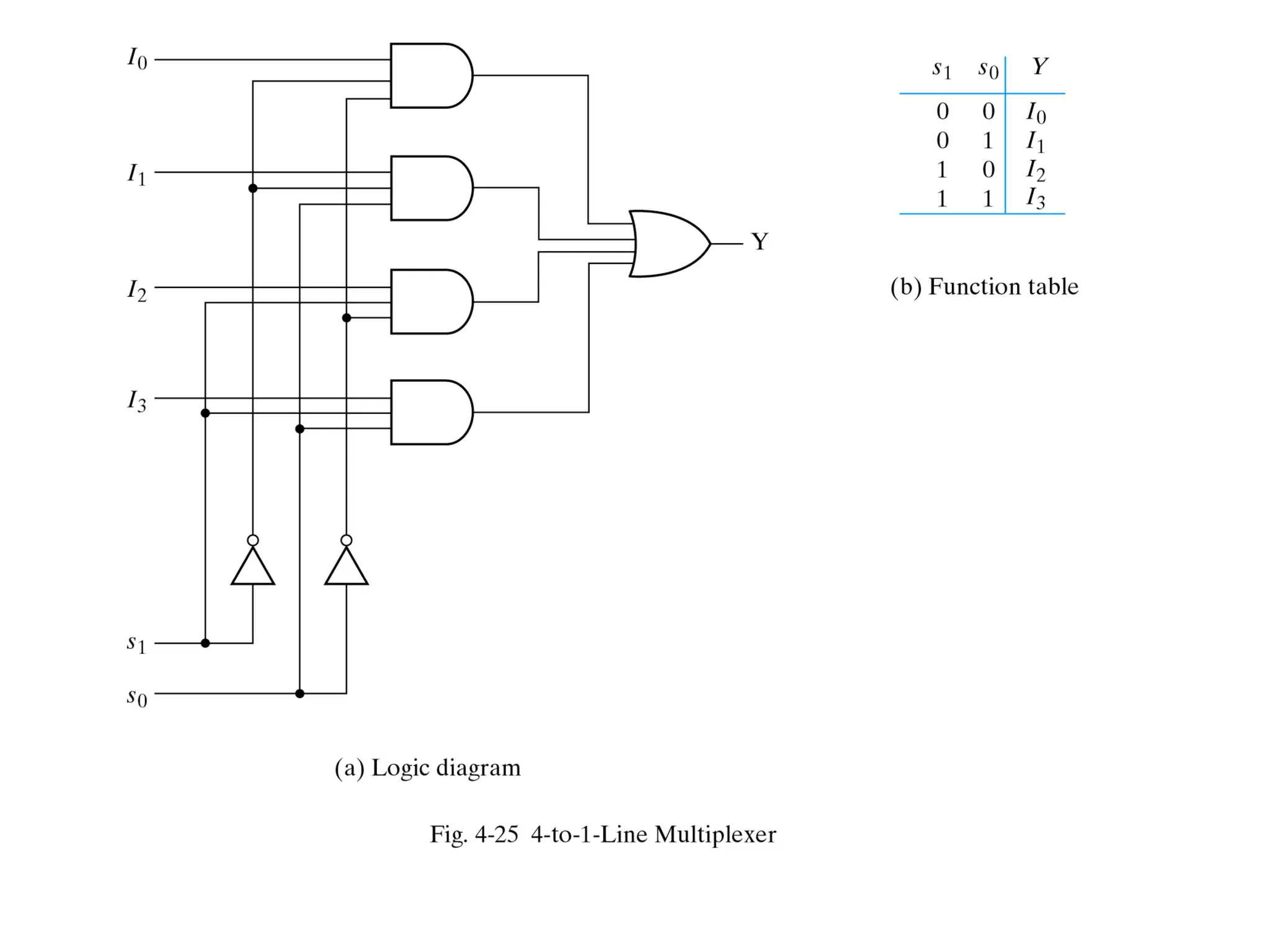
Usually there are 2n
input lines and n selection lines
whose bit combinations determine which input line is
selected
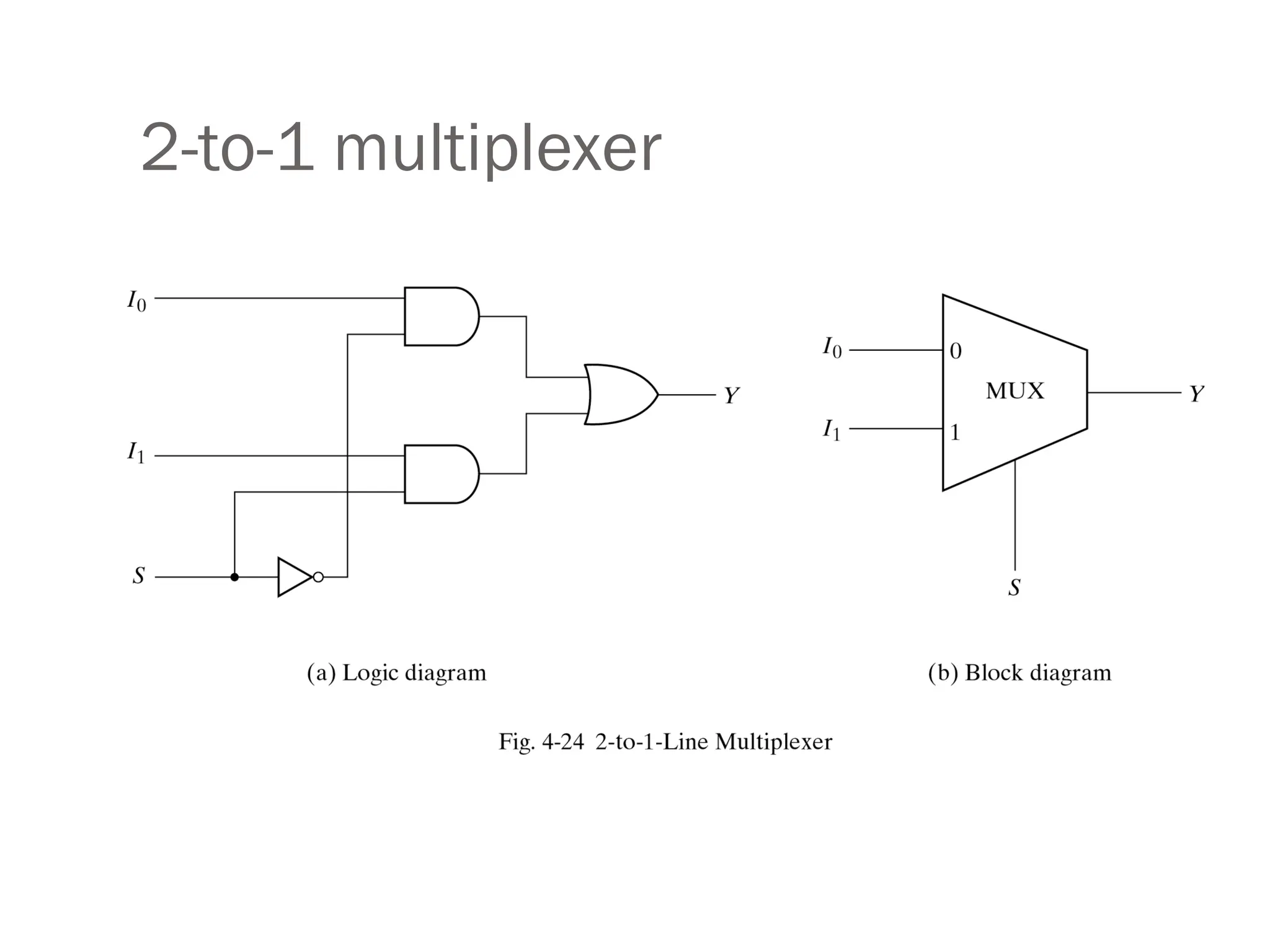
For example for 2-to-1 multiplexer if selection S is zero
then I0 has the path to output and if S is one I1 has the
path to output (see the next slide)
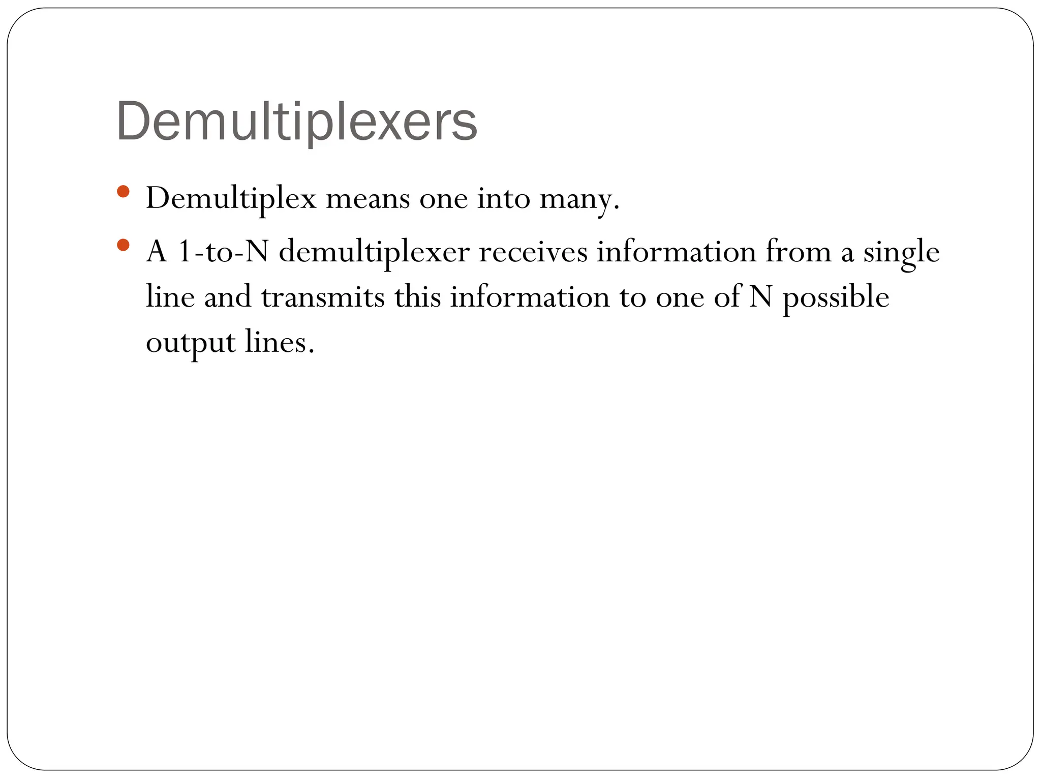
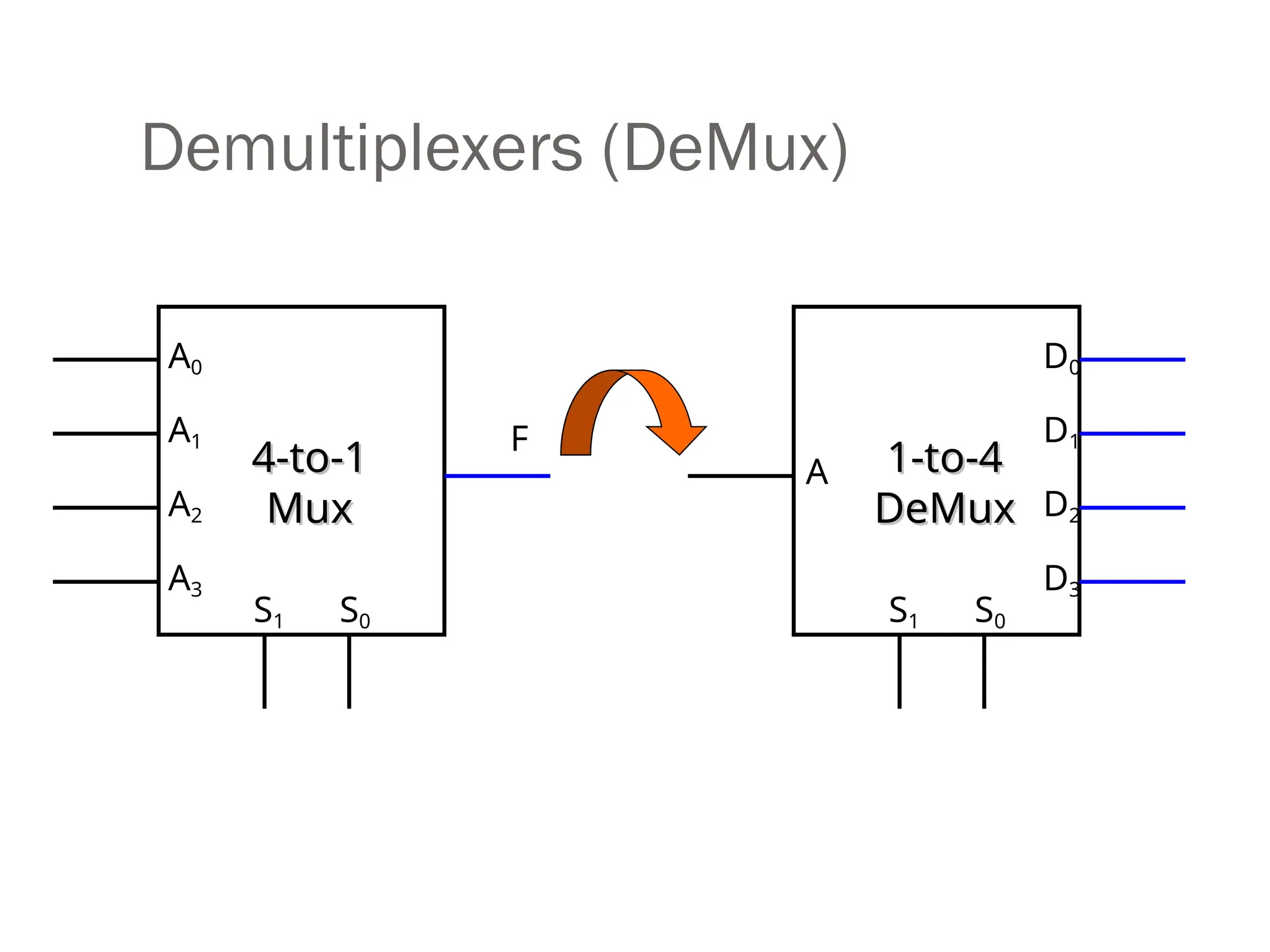
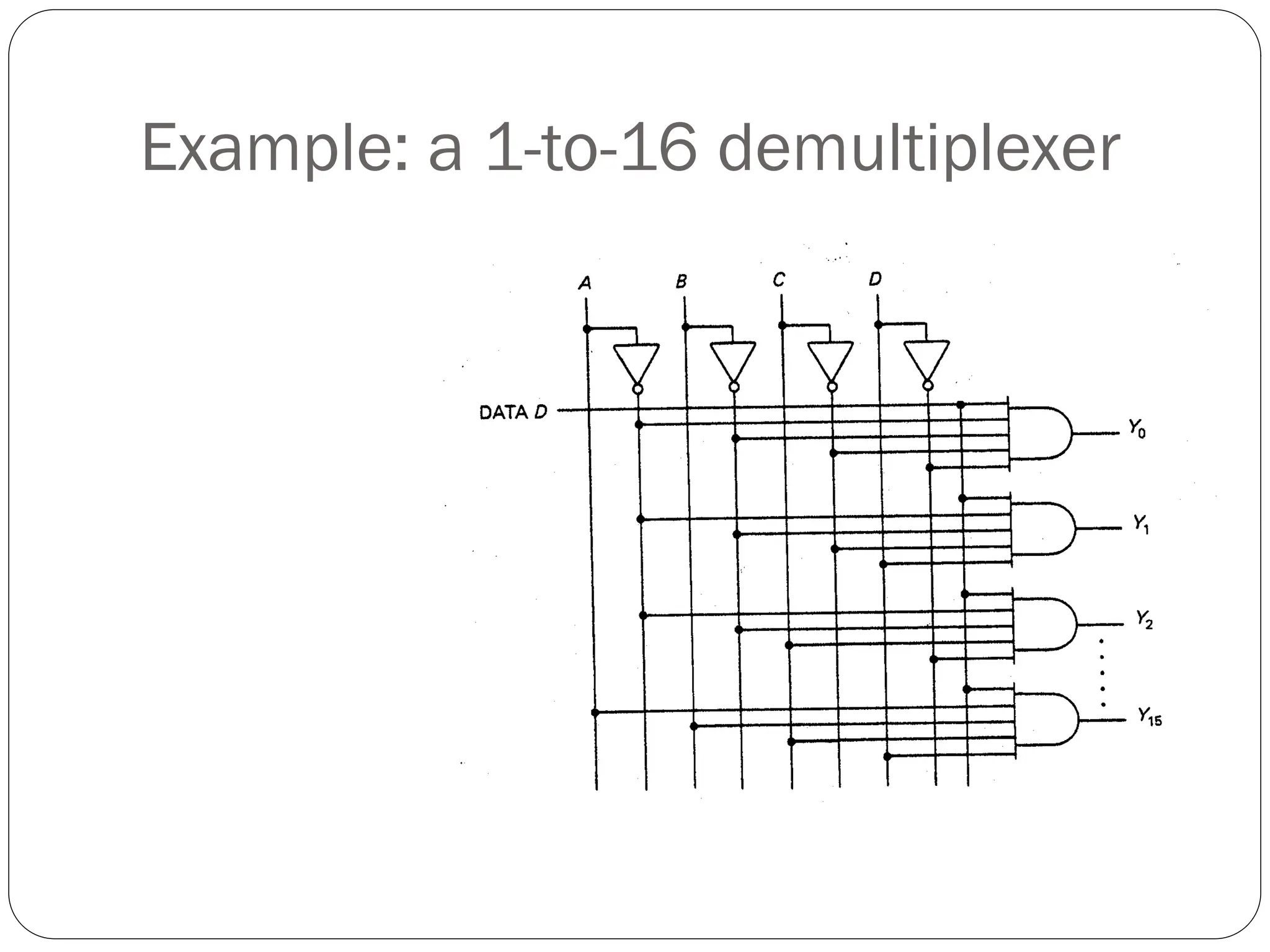
Demultiplexers
Demultiplex meansone into many.
A 1-to-N demultiplexer receives information from a single
line and transmits this information to one of N possible
output lines.
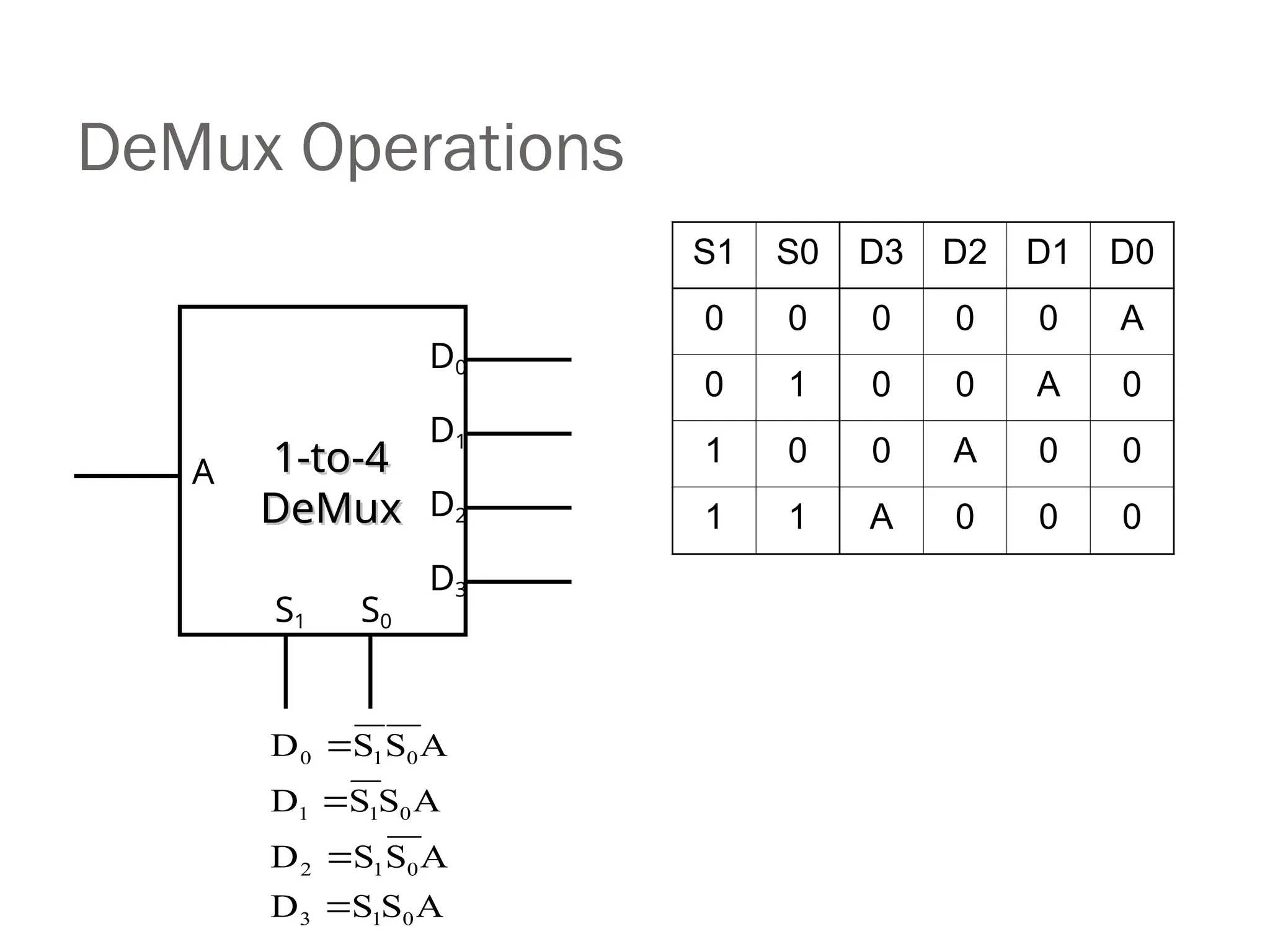
DeMux Operations
S1 S0D3 D2 D1 D0
0 0 0 0 0 A
0 1 0 0 A 0
1 0 0 A 0 0
1 1 A 0 0 0
A
S
S
D
A
S
S
D
A
S
S
D
A
S
S
D
0
1
3
0
1
2
0
1
1
0
1
0
A
D0
D1
D2
D3
S1 S0
1-to-4
1-to-4
DeMux
DeMux
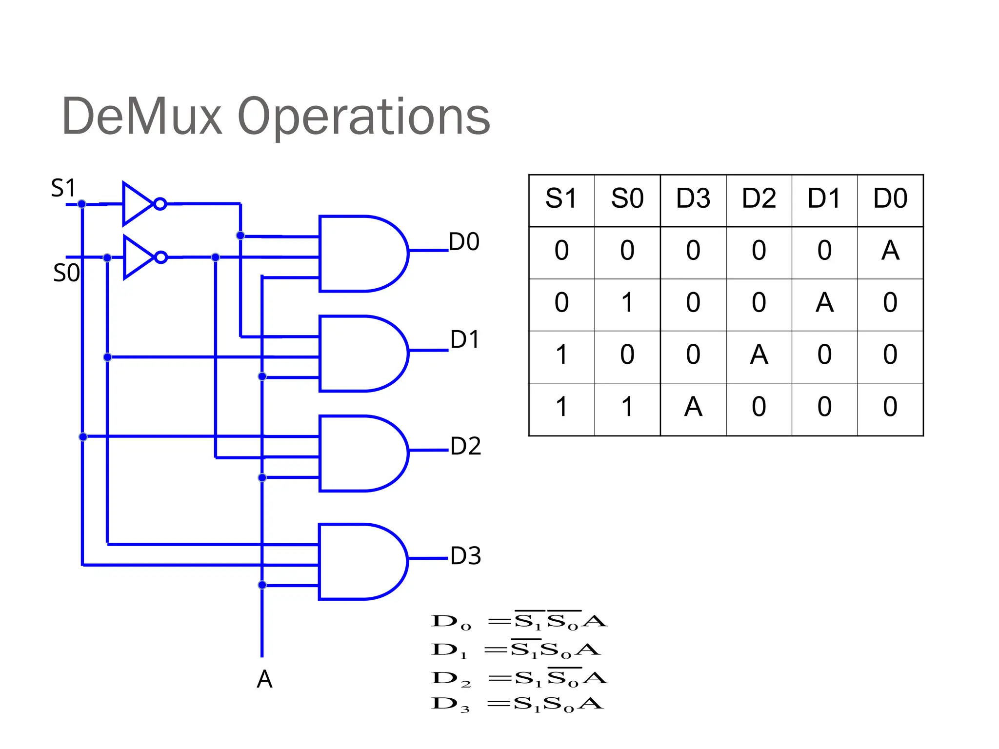
9.
DeMux Operations
S1 S0D3 D2 D1 D0
0 0 0 0 0 A
0 1 0 0 A 0
1 0 0 A 0 0
1 1 A 0 0 0
A
S
S
D
A
S
S
D
A
S
S
D
A
S
S
D
0
1
3
0
1
2
0
1
1
0
1
0
D0
D1
D2
D3
A
S1
S0
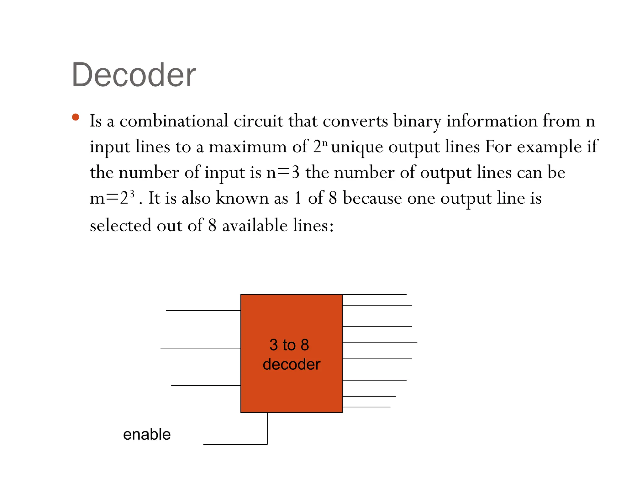
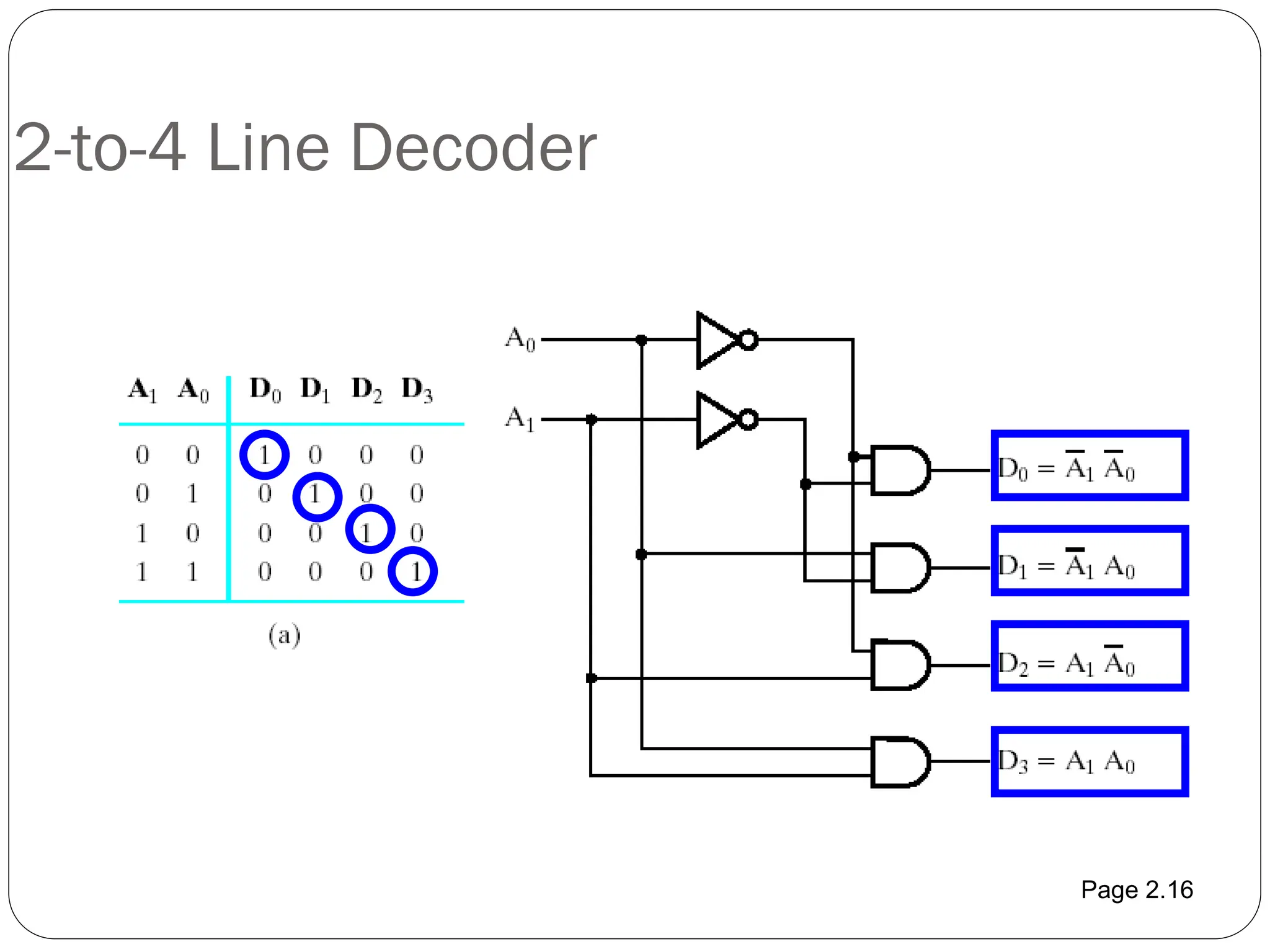
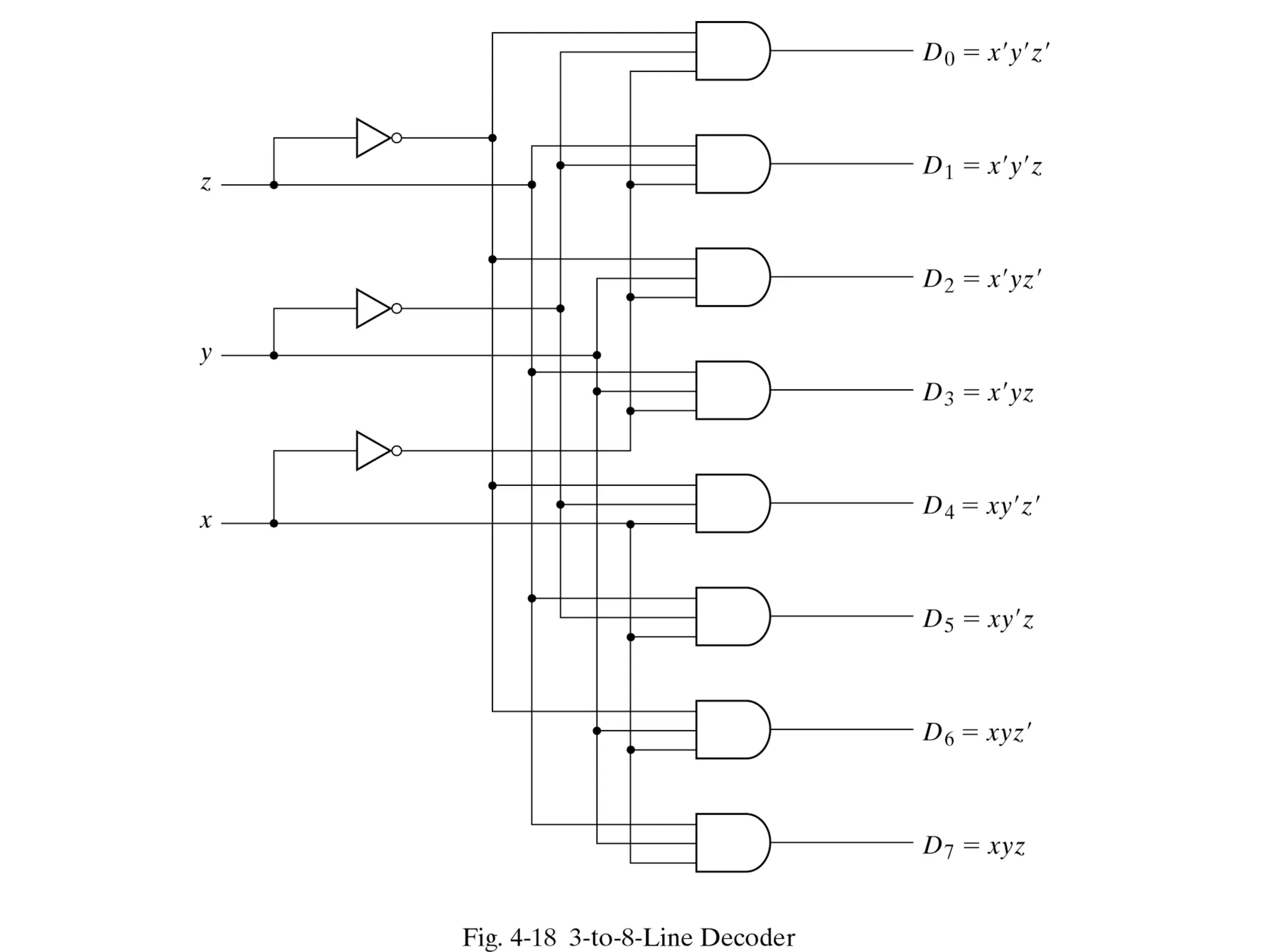
Decoder
Is acombinational circuit that converts binary information from n
input lines to a maximum of 2n
unique output lines For example if
the number of input is n=3 the number of output lines can be
m=23
. It is also known as 1 of 8 because one output line is
selected out of 8 available lines:
3 to 8
decoder
enable
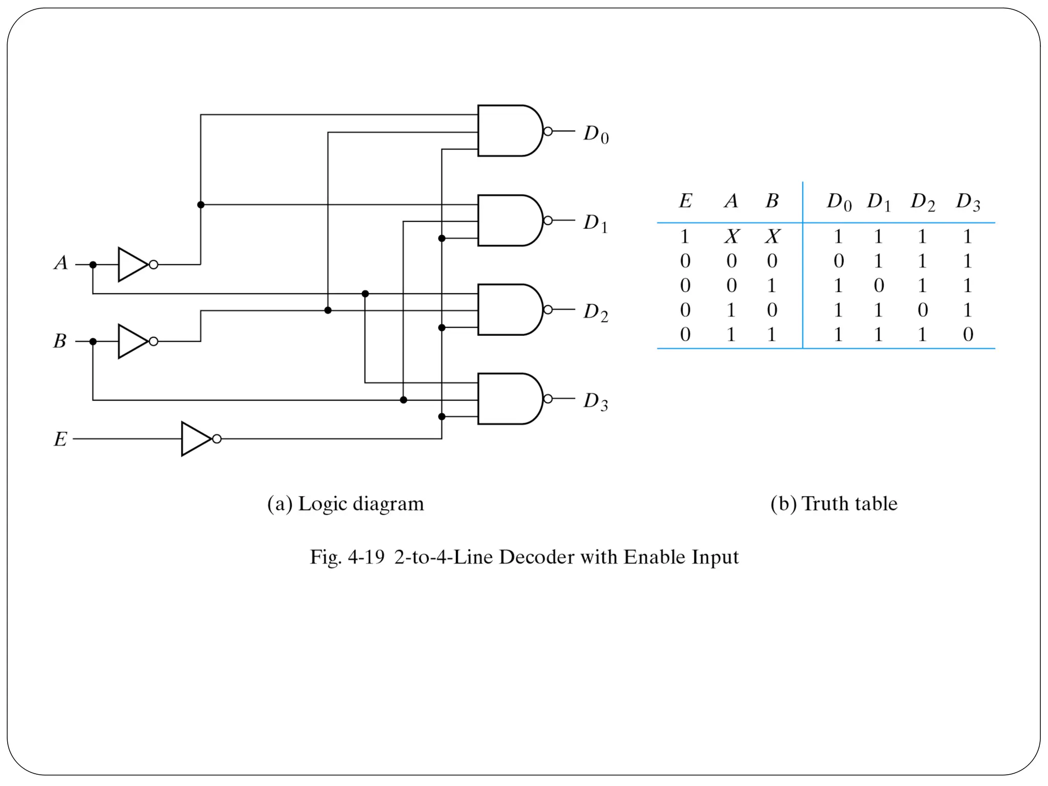
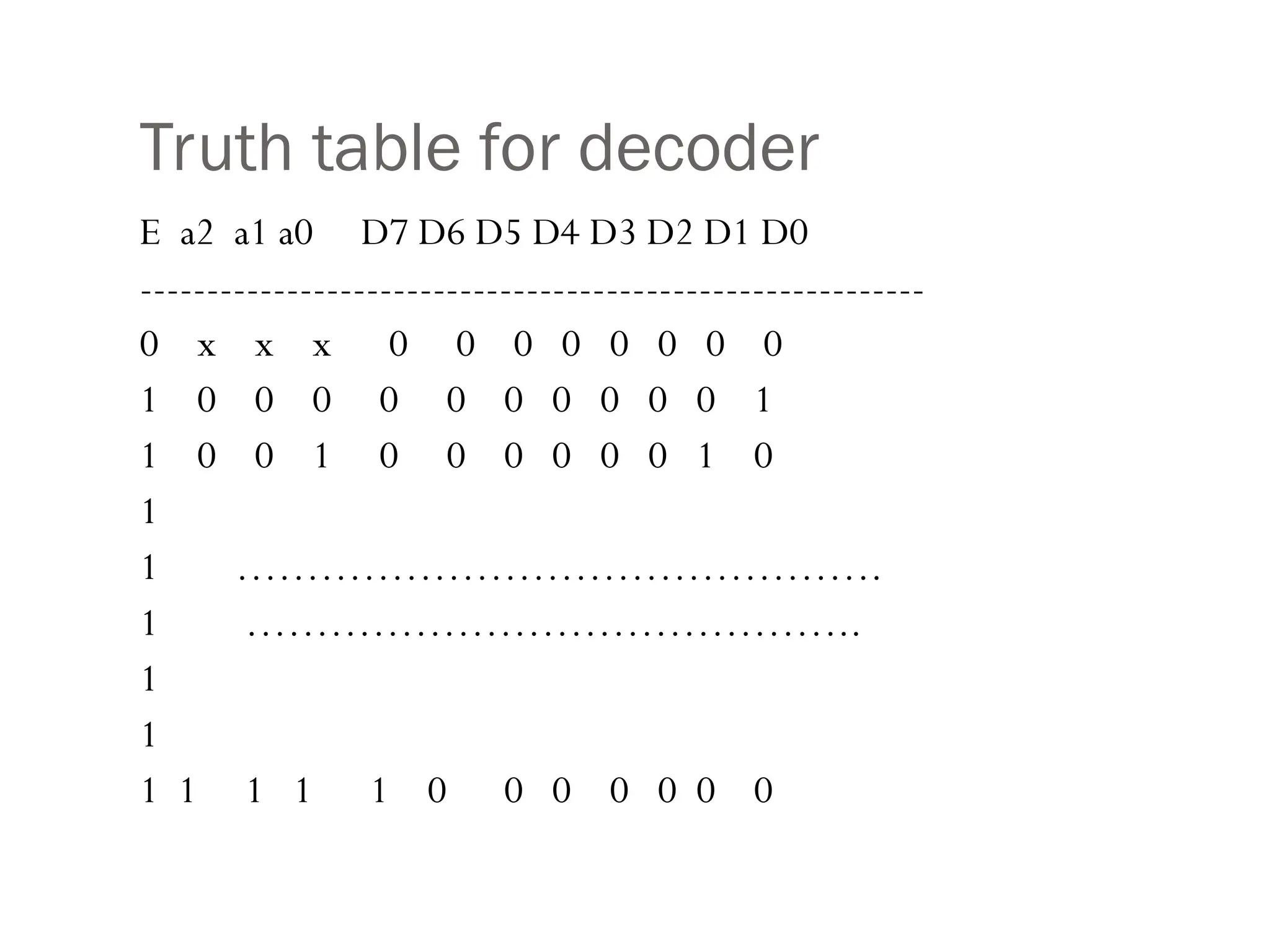
Decoder with EnableLine
Decoders usually have an enable line,
If enable=0 , decoder is off. It means all output lines are zero
If enable=1, decoder is on and depending on input, the
corresponding output line is 1, all other lines are 0
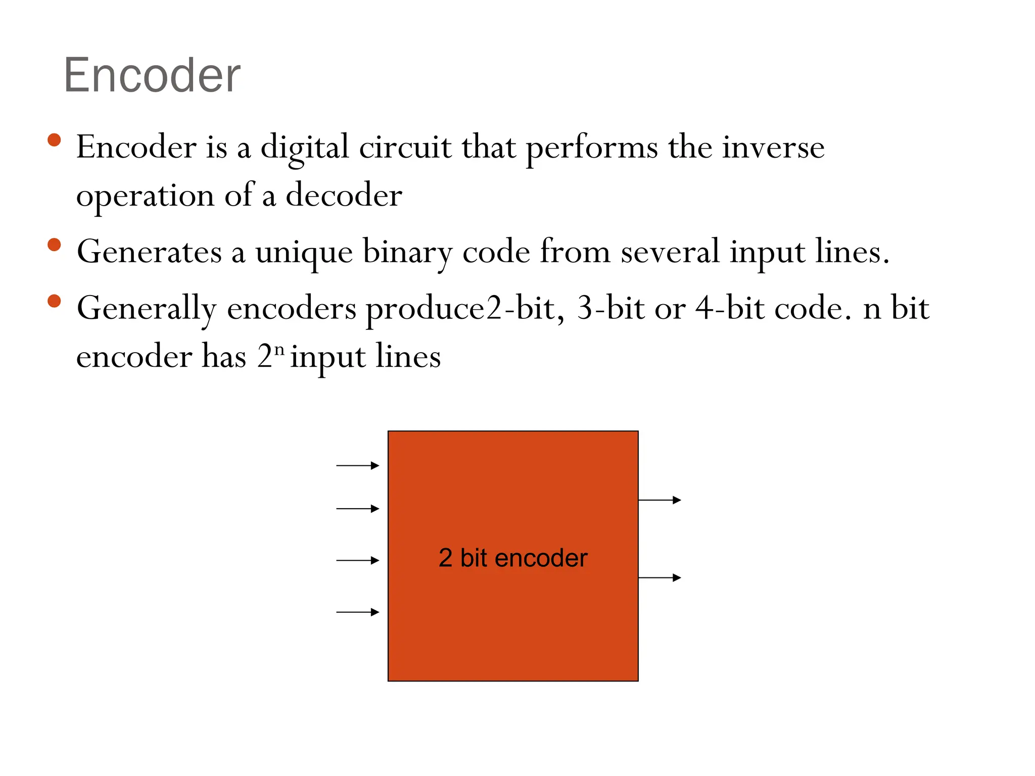
Encoder
Encoder isa digital circuit that performs the inverse
operation of a decoder
Generates a unique binary code from several input lines.
Generally encoders produce2-bit, 3-bit or 4-bit code. n bit
encoder has 2n
input lines
2 bit encoder
18.
2-bit encoder
Ifone of the four input lines is active encoder produces the
binary code corresponding to that line
If more than one of the input lines will be activated or all the
output is undefined. We can consider don’t care for these
situations but in general we can solve this problem by using
priority encoder.
19.
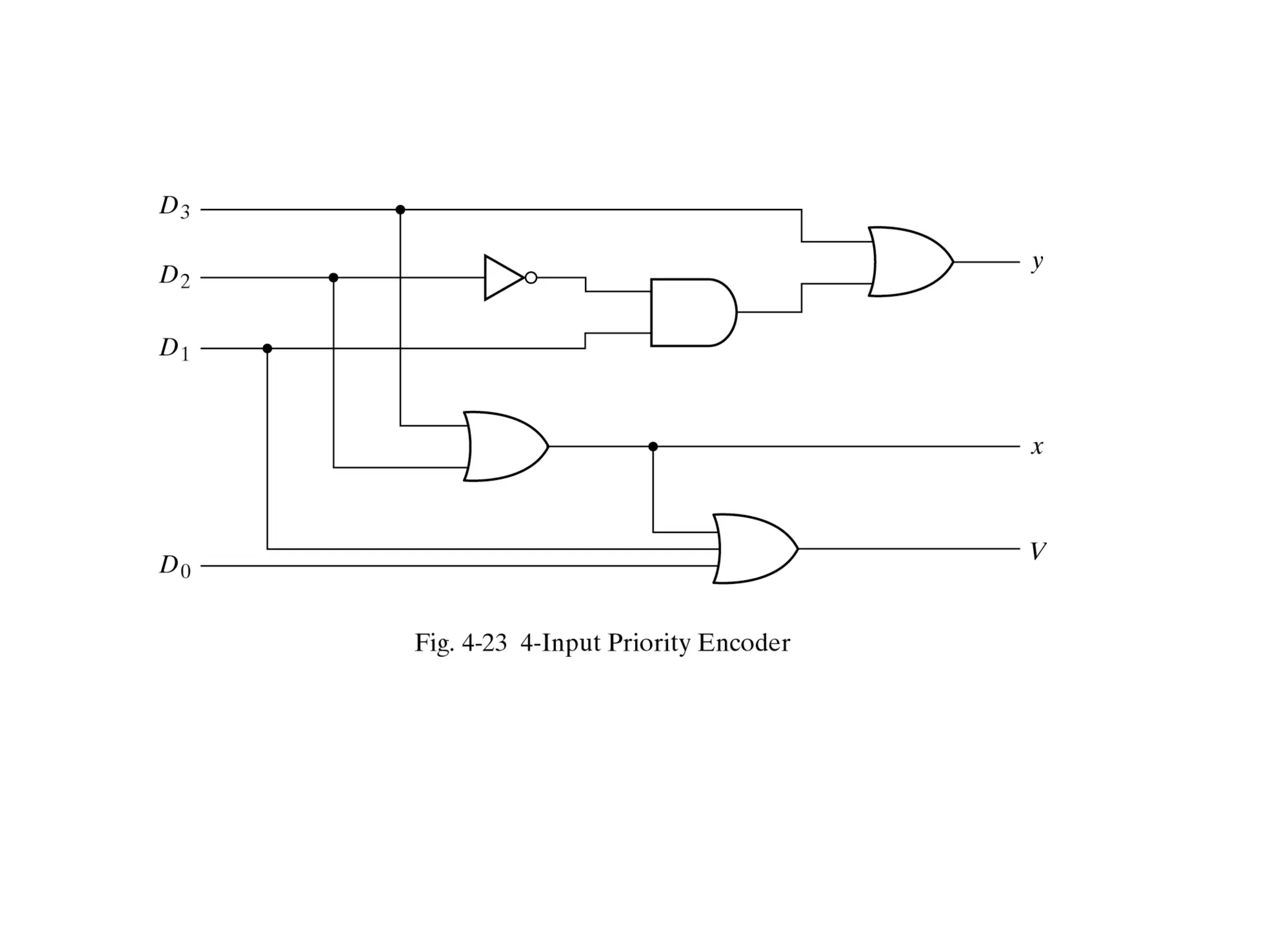
2-bit Priority Encoder
A priority encoder is an encoder circuit that includes priority
function.
It means if two or more inputs are equal to 1 at the same
time, the input having higher subscript number, considered
as a higher priority. For example if D3 is 1 regardless of the
value of the other input lines the result of output is 3 which
is 11.
21.
Adders
The functionof the adder circuits is to perform binary
arithmetic.
A major component in the CPU.
All kinds of arithmetic employ adders.
Half adder and full adder.
22.
Half Adder
Itperforms half of the one bit addition.
It adds two bits to give a sum and a carry.
It does not consider any carry input.
Therefore it called a half adder.
23.
Half-Adder
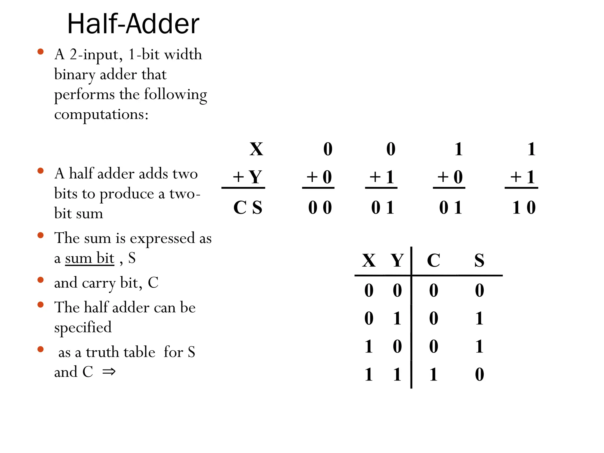
A 2-input,1-bit width
binary adder that
performs the following
computations:
A half adder adds two
bits to produce a two-
bit sum
The sum is expressed as
a sum bit , S
and carry bit, C
The half adder can be
specified
as a truth table for S
and C
X 0 0 1 1
+ Y + 0 + 1 + 0 + 1
C S 0 0 0 1 0 1 1 0
X Y C S
0 0 0 0
0 1 0 1
1 0 0 1
1 1 1 0
Full Adder
Thefull adder circuit is able to complete the full addition
process.
There are three inputs, the in carry, Ci, and the two binary
digits, A and B.
Outputs are sum, S, and an out carry, Co.
26.
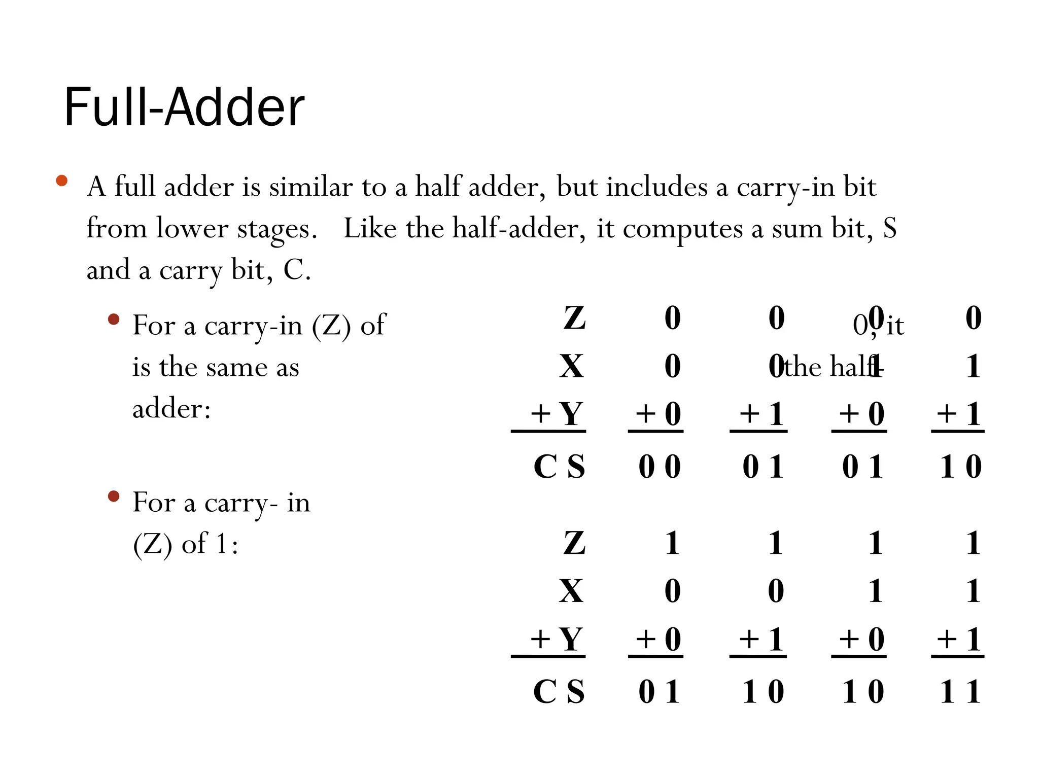
Full-Adder
A fulladder is similar to a half adder, but includes a carry-in bit
from lower stages. Like the half-adder, it computes a sum bit, S
and a carry bit, C.
For a carry-in (Z) of 0, it
is the same as the half-
adder:
For a carry- in
(Z) of 1:
Z 0 0 0 0
X 0 0 1 1
+ Y + 0 + 1 + 0 + 1
C S 0 0 0 1 0 1 1 0
Z 1 1 1 1
X 0 0 1 1
+ Y + 0 + 1 + 0 + 1
C S 0 1 1 0 1 0 1 1
27.
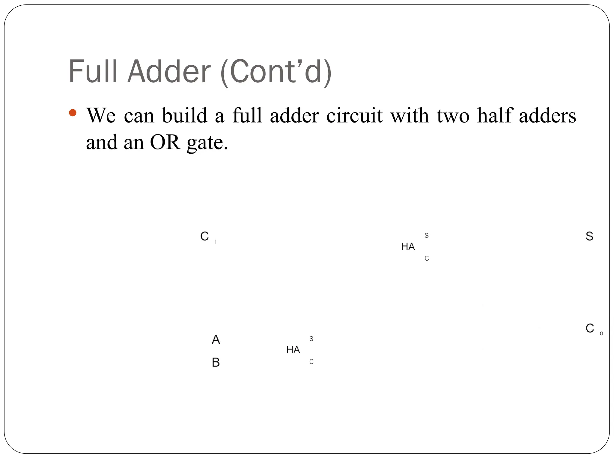
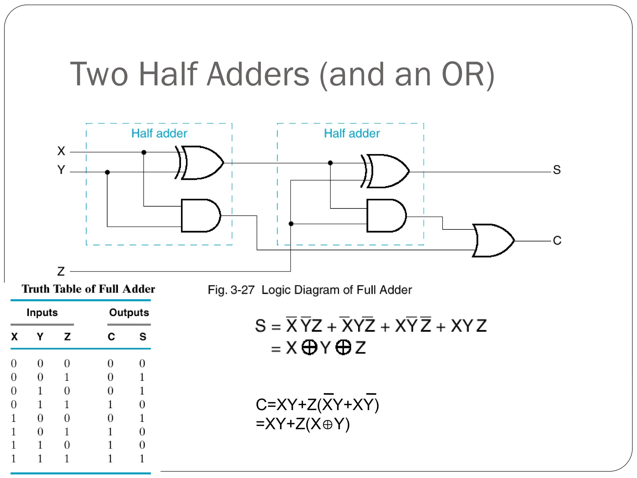
Full Adder (Cont’d)
We can build a full adder circuit with two half adders
and an OR gate.


![Analysis_Design_Procedures_with_Diagrams[1].pptx](https://cdn.slidesharecdn.com/ss_thumbnails/analysisdesignprocedureswithdiagrams1-250902110906-778fd956-thumbnail.jpg?width=640&height=640&fit=bounds)
![Analysis_Design_Procedures_with_Diagrams[1].pptx](https://cdn.slidesharecdn.com/ss_thumbnails/analysisdesignprocedureswithdiagrams1-250902110500-deeb2e09-thumbnail.jpg?width=640&height=640&fit=bounds)


