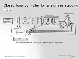
This document provides information about stepper motors, including:
1) Stepper motors rotate in discrete steps in response to input pulses, rather than continuously like conventional motors. They are well-suited for open-loop position control applications.
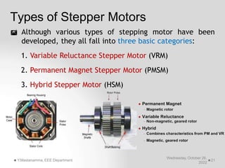
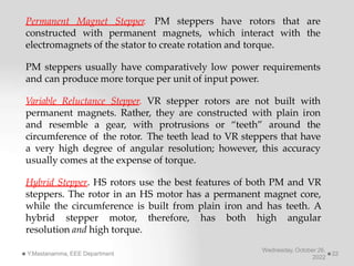
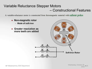
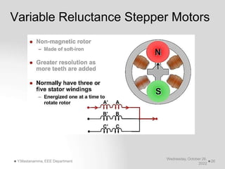
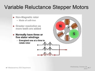
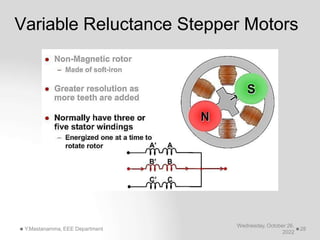
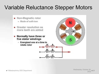
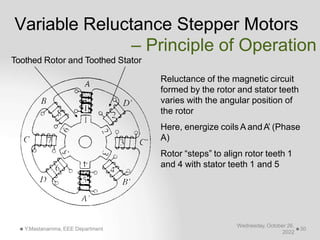
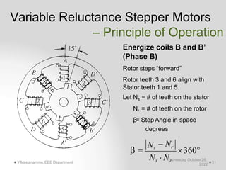
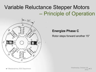
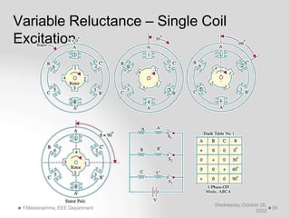
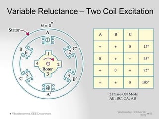
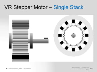
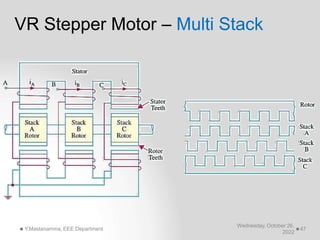
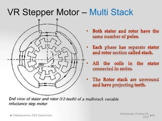
2) There are several common stepper motor types, including variable reluctance, permanent magnet, and hybrid stepper motors. Variable reluctance stepper motors have rotors made of iron teeth rather than magnets.
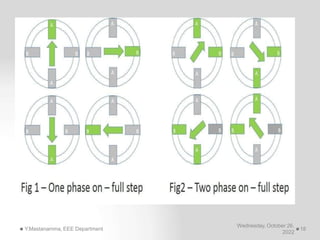
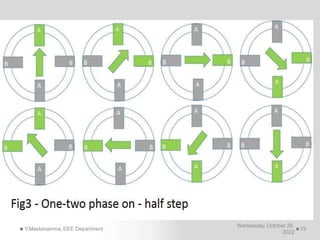
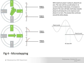
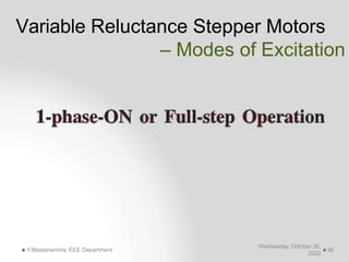
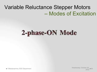
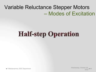
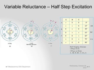
3) Stepper motors can operate in different modes like full step, half step, and microstep to achieve different torque and resolution levels. Higher resolution modes like microstepping reduce torque output.