2. Stepper Motor
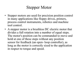
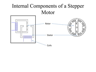
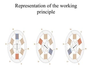
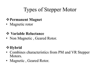
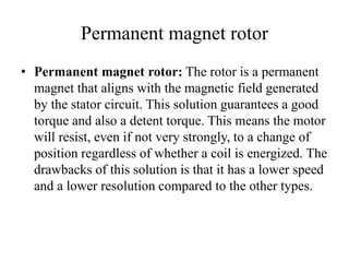
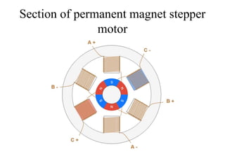
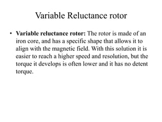
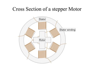
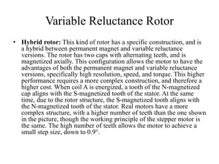
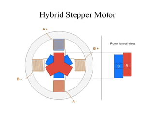
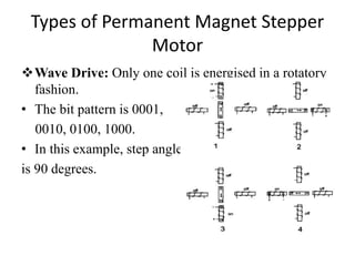
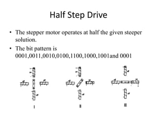
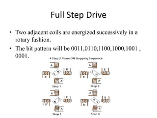
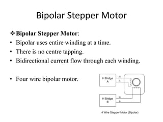
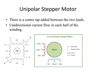
• Stepper motors are used for precision position control
in many applications like floppy drives, printers,
process control instruments, robotics and machine
tool control.
• A stepper motor is a brushless DC electric motor that
divides a full rotation into a number of equal steps.
The motor's position can be commanded to move and
hold at one of these steps without any position
sensor for feedback (an open- loop controller), as
long as the motor is correctly sized to the application
in respect to torque and speed.
3. Stepper Motor
• Brushless Digitally controlled motor
• Input is give in the form of electrical pulses.
• Converts Electric pulses into specific rotational
movements.
• Divides a full rotation into a large no of steps.
• Rotation in both directions.
5. Working Principle
• By energizing one or more of the stator phases, a
magnetic field is generated by the current flowing in
the coil and the rotor aligns with this field. By
supplying different phases in sequence, the rotor can be
rotated by a specific amount to reach the desired final
position. At the beginning, coil A is energized and the
rotor is aligned with the magnetic field it produces.
When coil B is energized, the rotor rotates clockwise by
60° to align with the new magnetic field. The same
happens when coil C is energized. In the pictures, the
colors of the stator teeth indicate the direction of the
magnetic field generated by the stator winding.
7. Types of Stepper Motor
Permanent Magnet
• Magnetic rotor
Variable Reluctance
• Non Magnetic , Geared Rotor.
Hybrid
• Combines characteristics from PM and VR Stepper
Motors.
• Magnetic , Geared Rotor.
8. Permanent magnet rotor
• Permanent magnet rotor: The rotor is a permanent
magnet that aligns with the magnetic field generated
by the stator circuit. This solution guarantees a good
torque and also a detent torque. This means the motor
will resist, even if not very strongly, to a change of
position regardless of whether a coil is energized. The
drawbacks of this solution is that it has a lower speed
and a lower resolution compared to the other types.
10. Variable Reluctance rotor
• Variable reluctance rotor: The rotor is made of an
iron core, and has a specific shape that allows it to
align with the magnetic field. With this solution it is
easier to reach a higher speed and resolution, but the
torque it develops is often lower and it has no detent
torque.
12. Variable Reluctance Rotor
• Hybrid rotor: This kind of rotor has a specific construction, and is
a hybrid between permanent magnet and variable reluctance
versions. The rotor has two caps with alternating teeth, and is
magnetized axially. This configuration allows the motor to have the
advantages of both the permanent magnet and variable reluctance
versions, specifically high resolution, speed, and torque. This higher
performance requires a more complex construction, and therefore a
higher cost. When coil A is energized, a tooth of the N-magnetized
cap aligns with the S-magnetized tooth of the stator. At the same
time, due to the rotor structure, the S-magnetized tooth aligns with
the N-magnetized tooth of the stator. Real motors have a more
complex structure, with a higher number of teeth than the one shown
in the picture, though the working principle of the stepper motor is
the same. The high number of teeth allows the motor to achieve a
small step size, down to 0.9°.
14. Types of Permanent Magnet Stepper
Motor
Wave Drive: Only one coil is energised in a rotatory
fashion.
• The bit pattern is 0001,
0010, 0100, 1000.
• In this example, step angle
is 90 degrees.
15. Half Step Drive
• The stepper motor operates at half the given steeper
solution.
• The bit pattern is
0001,0011,0010,0100,1100,1000,1001and 0001
16. Full Step Drive
• Two adjacent coils are energized successively in a
rotary fashion.
• The bit pattern will be 0011,0110,1100,1000,1001 ,
0001.
17. Bipolar Stepper Motor
Bipolar Stepper Motor:
• Bipolar uses entire winding at a time.
• There is no centre tapping.
• Bidirectional current flow through each winding.
• Four wire bipolar motor.
18. Unipolar Stepper Motor
• There is a centre tap added between the two leads.
• Unidirectional current flow in each half of the
winding.