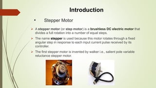
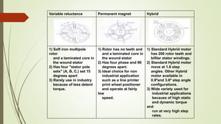
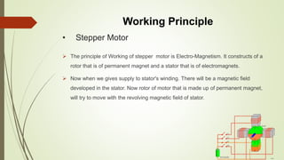
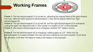
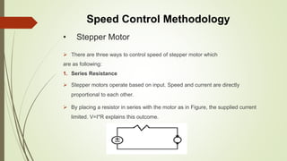
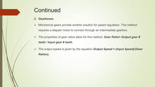
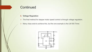
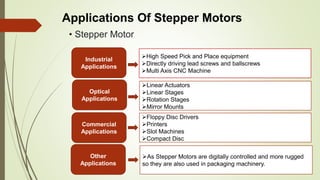
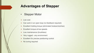
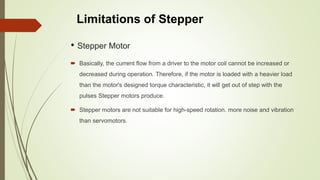
Stepper Motor
Presentation Topic
Group Members
Syed Muhammad Abbas.
Tufail khan.
Saad Khan
Contents
 Introduction
 Working Principle
 Speed Control Methodology
 Applications
 Advantages
 Limitations
 References
 Q & A
• Stepper Motor
 A stepper motor (or step motor) is a brushless DC electric motor that
divides a full rotation into a number of equal steps.
 The name stepper is used because this motor rotates through a fixed
angular step in response to each input current pulse received by its
controller.
 The first stepper motor is invented by walker i.e., salient pole variable
reluctance stepper motor.
Introduction
• Types of Stepper Motor
 Three types of stepper motor:
1. -Permanent magnet
2. -Hybrid
3. -Variable reluctance
Variable reluctance Permanent magnet Hybrid
1) Soft iron multipole
rotor
and a laminated core in
the wound stator
2) Has four "stator pole
sets" (A, B, C,) set 15
degrees apart
3) Rarely use in industry
because of less detent
torque.
1) Rotor has no teeth and
and a laminated core in
the wound stator
2) Has four phase and 90
degrees apart.
3) Ideal choice for non
industrial application
such as a line printer
print wheel positioner
and operate at fairly
low
speed.
1) Standard Hybrid motor
has 200 rotor teeth and
bifilar stator windings.
2) Standard Hybrid motor
move at 1.8 step
angles. Other Hybrid
motor available in
0.9ºand 3.6º step angle
configurations.
3) Wide variety used for
industrial applications
because of high static
and dynamic torque
and
run at very high step
rates.
• Stepper Motor
 The principle of Working of stepper motor is Electro-Magnetism. It constructs of a
rotor that is of permanent magnet and a stator that is of electromagnets.
 Now when we gives supply to stator's winding. There will be a magnetic field
developed in the stator. Now rotor of motor that is made up of permanent magnet,
will try to move with the revolving magnetic field of stator.
Working Principle
Frame 1: The top electromagnet (1) is turned on, attracting the nearest teeth of the gear-shaped
iron rotor. With the teeth aligned to electromagnet 1, they will be slightly offset from right
electromagnet (2).
Frame 2: The top electromagnet (1) is turned off, and the right electromagnet (2) is energized,
pulling the teeth into alignment with it. This results in a rotation of 3.6° in this example.
Frame 3: The bottom electromagnet (3) is energized; another 3.6° rotation occurs.
Frame 4: The left electromagnet (4) is energized, rotating again by 3.6°. When the top
electromagnet (1) is again enabled, the rotor will have rotated by one tooth position; since there
are 25 teeth, it will take 100 steps to make a full rotation in this example.
Working Frames
• Stepper Motor
 There are three ways to control speed of stepper motor which
are as following:
1. Series Resistance
 Stepper motors operate based on input. Speed and current are directly
proportional to each other.
 By placing a resistor in series with the motor as in Figure, the supplied current
limited. V=I*R explains this outcome.
Speed Control Methodology
Continued
2. Gearboxes
 Mechanical gears provide another solution for speed regulation. This method
requires a stepper motor to connect through an intermediate gearbox.
 The properties of gear ratios allow for this method. Gear Ratio= Output gear #
teeth / Input gear # teeth.
 The output speed is given by the equation Output Speed = (Input Speed)/(Gear
Ration).
Continued
3. Voltage Regulation
 The final method for stepper motor speed control is through voltage regulation.
 Many chips exist to achieve this, but the one example is the LM 555 Timer.
• Stepper Motor
Applications Of Stepper Motors
Industrial
Applications
Optical
Applications
Commercial
Applications
Other
Applications
High Speed Pick and Place equipment
Directly driving lead screws and ballscrews
Multi Axis CNC Machine
Linear Actuators
Linear Stages
Rotation Stages
Mirror Mounts
Floppy Disc Drivers
Printers
Slot Machines
Compact Disc
As Stepper Motors are digitally controlled and more rugged
so they are also used in packaging machinery.
• Stepper Motor
 Low cost
 Can work in an open loop (no feedback required)
 Excellent holding torque (eliminated brakes/clutches)
 Excellent torque at low speeds
 Low maintenance (brushless)
 Very rugged - any environment
 Excellent for precise positioning control
 No tuning required
Advantages of Stepper
• Stepper Motor
 Basically, the current flow from a driver to the motor coil cannot be increased or
decreased during operation. Therefore, if the motor is loaded with a heavier load
than the motor's designed torque characteristic, it will get out of step with the
pulses Stepper motors produce.
 Stepper motors are not suitable for high-speed rotation. more noise and vibration
than servomotors.
Limitations of Stepper
References
 www.google.com
 www.wikipedia.org
 www.slideshare.net
 www.tigertek.com
 www.electromate.wordpress.com
 www.hansen-motor.com
 Electric Machinery Fundamentals By Stephen Chapman
 Setpper Motor

Setpper Motor

  • 1.
  • 2.
    Group Members Syed MuhammadAbbas. Tufail khan. Saad Khan
  • 3.
    Contents  Introduction  WorkingPrinciple  Speed Control Methodology  Applications  Advantages  Limitations  References  Q & A
  • 4.
    • Stepper Motor A stepper motor (or step motor) is a brushless DC electric motor that divides a full rotation into a number of equal steps.  The name stepper is used because this motor rotates through a fixed angular step in response to each input current pulse received by its controller.  The first stepper motor is invented by walker i.e., salient pole variable reluctance stepper motor. Introduction
  • 5.
    • Types ofStepper Motor  Three types of stepper motor: 1. -Permanent magnet 2. -Hybrid 3. -Variable reluctance
  • 6.
    Variable reluctance Permanentmagnet Hybrid 1) Soft iron multipole rotor and a laminated core in the wound stator 2) Has four "stator pole sets" (A, B, C,) set 15 degrees apart 3) Rarely use in industry because of less detent torque. 1) Rotor has no teeth and and a laminated core in the wound stator 2) Has four phase and 90 degrees apart. 3) Ideal choice for non industrial application such as a line printer print wheel positioner and operate at fairly low speed. 1) Standard Hybrid motor has 200 rotor teeth and bifilar stator windings. 2) Standard Hybrid motor move at 1.8 step angles. Other Hybrid motor available in 0.9ºand 3.6º step angle configurations. 3) Wide variety used for industrial applications because of high static and dynamic torque and run at very high step rates.
  • 7.
    • Stepper Motor The principle of Working of stepper motor is Electro-Magnetism. It constructs of a rotor that is of permanent magnet and a stator that is of electromagnets.  Now when we gives supply to stator's winding. There will be a magnetic field developed in the stator. Now rotor of motor that is made up of permanent magnet, will try to move with the revolving magnetic field of stator. Working Principle
  • 8.
    Frame 1: Thetop electromagnet (1) is turned on, attracting the nearest teeth of the gear-shaped iron rotor. With the teeth aligned to electromagnet 1, they will be slightly offset from right electromagnet (2). Frame 2: The top electromagnet (1) is turned off, and the right electromagnet (2) is energized, pulling the teeth into alignment with it. This results in a rotation of 3.6° in this example. Frame 3: The bottom electromagnet (3) is energized; another 3.6° rotation occurs. Frame 4: The left electromagnet (4) is energized, rotating again by 3.6°. When the top electromagnet (1) is again enabled, the rotor will have rotated by one tooth position; since there are 25 teeth, it will take 100 steps to make a full rotation in this example. Working Frames
  • 9.
    • Stepper Motor There are three ways to control speed of stepper motor which are as following: 1. Series Resistance  Stepper motors operate based on input. Speed and current are directly proportional to each other.  By placing a resistor in series with the motor as in Figure, the supplied current limited. V=I*R explains this outcome. Speed Control Methodology
  • 10.
    Continued 2. Gearboxes  Mechanicalgears provide another solution for speed regulation. This method requires a stepper motor to connect through an intermediate gearbox.  The properties of gear ratios allow for this method. Gear Ratio= Output gear # teeth / Input gear # teeth.  The output speed is given by the equation Output Speed = (Input Speed)/(Gear Ration).
  • 11.
    Continued 3. Voltage Regulation The final method for stepper motor speed control is through voltage regulation.  Many chips exist to achieve this, but the one example is the LM 555 Timer.
  • 12.
    • Stepper Motor ApplicationsOf Stepper Motors Industrial Applications Optical Applications Commercial Applications Other Applications High Speed Pick and Place equipment Directly driving lead screws and ballscrews Multi Axis CNC Machine Linear Actuators Linear Stages Rotation Stages Mirror Mounts Floppy Disc Drivers Printers Slot Machines Compact Disc As Stepper Motors are digitally controlled and more rugged so they are also used in packaging machinery.
  • 13.
    • Stepper Motor Low cost  Can work in an open loop (no feedback required)  Excellent holding torque (eliminated brakes/clutches)  Excellent torque at low speeds  Low maintenance (brushless)  Very rugged - any environment  Excellent for precise positioning control  No tuning required Advantages of Stepper
  • 14.
    • Stepper Motor Basically, the current flow from a driver to the motor coil cannot be increased or decreased during operation. Therefore, if the motor is loaded with a heavier load than the motor's designed torque characteristic, it will get out of step with the pulses Stepper motors produce.  Stepper motors are not suitable for high-speed rotation. more noise and vibration than servomotors. Limitations of Stepper
  • 15.
    References  www.google.com  www.wikipedia.org www.slideshare.net  www.tigertek.com  www.electromate.wordpress.com  www.hansen-motor.com  Electric Machinery Fundamentals By Stephen Chapman