This document provides an overview of stepper motors, including:
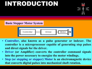
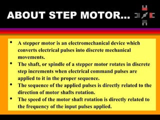
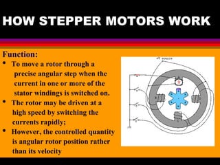
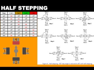
- How stepper motors work by converting electrical pulses into discrete mechanical movements of the motor shaft.
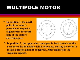
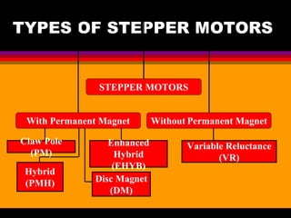
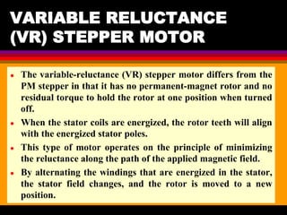
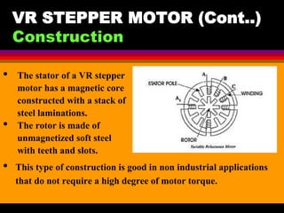
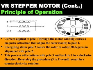
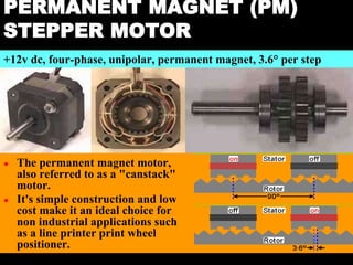
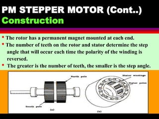
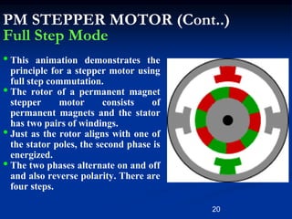
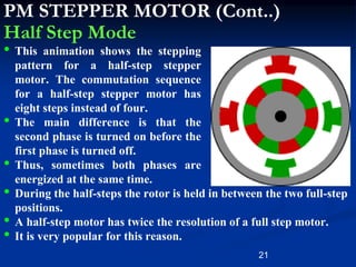
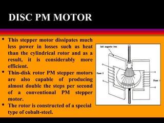
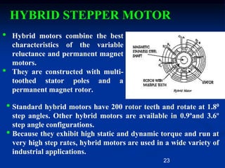
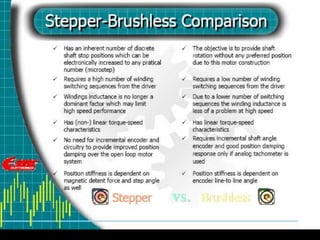
- The main types of stepper motors: variable reluctance, permanent magnet, and hybrid. It describes the construction and operation of each type.
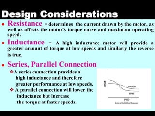
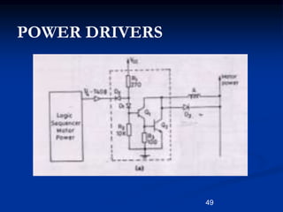
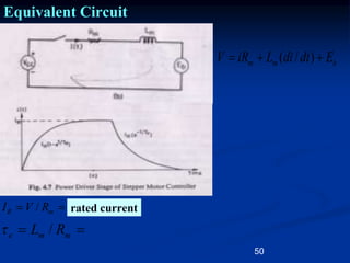
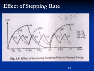
- Design considerations for stepper motors like resistance, inductance, and driver voltage which impact torque and speed.
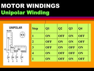
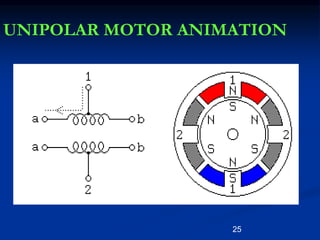
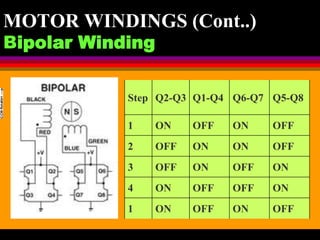
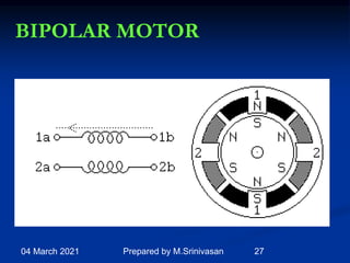
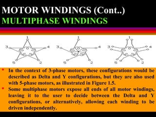
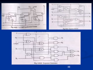
The document contains diagrams and explanations of the internal components and winding configurations of different stepper motor types.