Downloaded 243 times
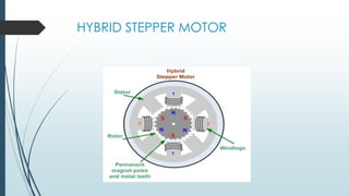
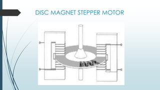


This document is a seminar paper submitted by V. Sumanth to partial fulfillment of a Bachelor of Technology degree in Electrical and Electronics Engineering. The paper discusses stepper motors, including their principle of operation, types, parameters, stepping modes, characteristics, applications, and conclusions. Stepper motors are brushless DC motors that rotate in discrete angular increments when their stator is energized in a programmed manner. The paper covers various types of stepper motors including variable reluctance, claw pole, hybrid, and disc magnet stepper motors.