Downloaded 553 times
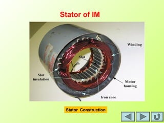
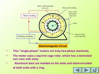
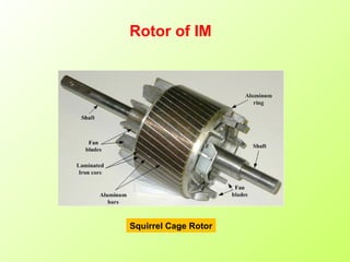
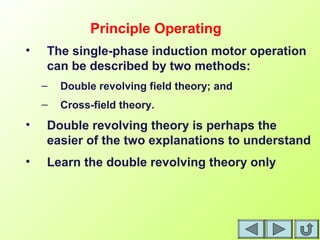


This document provides an overview of single-phase induction motors. It discusses the construction of single-phase induction motors, which have a two-winding stator arranged perpendicularly and a squirrel cage rotor. It explains that these motors operate based on a double revolving field theory, where the pulsating magnetic field from the main winding can be divided into two fields rotating in opposite directions. A starting winding is used to generate a small positive slip and produce starting torque to initially rotate the motor in the forward direction of one of the fields. An equivalent circuit model is presented to analyze the motor performance based on the two rotating fields.