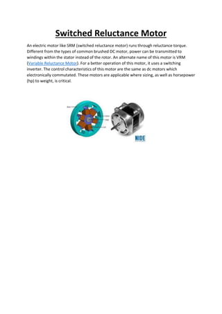
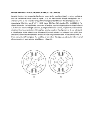
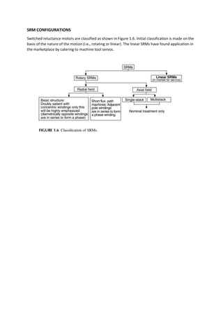
Switched Reluctance Motor
An electric motor like SRM (switched reluctance motor) runs through reluctance torque.
Different from the types of common brushed DC motor, power can be transmitted to
windings within the stator instead of the rotor. An alternate name of this motor is VRM
(Variable Reluctance Motor). For a better operation of this motor, it uses a switching
inverter. The control characteristics of this motor are the same as dc motors which
electronically commutated. These motors are applicable where sizing, as well as horsepower
(hp) to weight, is critical.
Working Principle
The working principle of the switched reluctance motor is, it works on the principle of
variable reluctance that means, the rotor of this motor constantly tries to align through the
lowest reluctance lane.
The formation of the rotary magnetic field can be done using the circuit of power
electronics switching. In this, the magnetic circuit’s reluctance can mainly depend on the air
gap. Therefore, by modifying the air gap among the rotor as well as a stator, we can also
modify the reluctance of this motor.
Here, reluctance can be defined as resistance toward the magnetic flux. For Electrical
circuits, reluctance is the combination of resistance as well as the magnetic circuit.
ELEMENTARY OPERATION OF THE SWITCHED RELUCTANCE MOTOR
Consider that the rotor poles r1 and and stator poles c and c′ are aligned. Apply a current to phase a
with the current direction as shown in Figure 1.2a. A flux is established through stator poles a and a′
and rotor poles r2 and which tends to pull the rotor poles r2 and toward the stator poles a and a′,
respectively. When they are r1 ′ r2 ′ r2 ′ 0838_frame_C01 Page 2 Wednesday, May 16, 2001 1:36 PM
aligned, the stator current of phase a is turned off and the corresponding situation is shown in Figure
1.2b. Now the stator winding b is excited, pulling r1 and toward b and b′, respectively, in a clockwise
direction. Likewise, energization of the c phase winding results in the alignment of r2 and with c and
c′, respectively. Hence, it takes three phase energizations in sequence to move the rotor by 90°, and
one revolution of rotor movement is effected by switching currents in each phase as many times as
there are number of rotor poles. The switching of currents in the sequence acb results in the reversal
of rotor rotation is seen with the aid of Figures 1.2a and b.
Four distinct inductance regions emerge:
1. 0 − θ1 and θ4 − θ5: The stator and rotor poles are not overlapping in this region and the flux is
predominantly determined by the air path, thus making the inductance minimum and almost a
constant. Hence, these regions do not contribute to torque production. The inductance in this region
is known as unaligned inductance, Lu.
2. θ1 − θ2: Poles overlap, so the flux path is mainly through stator and rotor laminations. This
increases the inductance with the rotor position, giving it a positive slope. A current impressed in
the winding during this region produces a positive (i.e., motoring) torque. This region comes to an
end when the overlap of poles is complete. FIGURE 1.4 Derivation of inductance vs. rotor position
from rotor and stator pole arcs for an unsaturated switched reluctance machine. (a) Basic rotor
position definition in a two pole SRM. (b) Inductance profile. 1θ 5θ (a) βs βr θ θθ 1 23 θ4 θ5 θ1 a u L
L Rotor Position (b) 0838_frame_C01 Page 8 Wednesday, May 16, 2001 1:36 PM
3. θ2 − θ3: During this period, movement of rotor pole does not alter the complete overlap of the
stator pole and does not change the dominant flux path. This has the effect of keeping the
inductance maximum and constant, and this inductance is known as aligned inductance, La. As there
is no change in the inductance in this region, torque generation is zero even when a current is
present in this interval. In spite of this fact, it serves a useful function by providing time for the stator
current to come to zero or lower levels when it is commutated, thus preventing negative torque
generation for part of the time if the current has been decaying in the negative slope region of the
inductance.
4. θ3 − θ4: The rotor pole is moving away from overlapping the stator pole in this region. This is very
much similar to the θ1 − θ2 region, but it has decreasing inductance and increasing rotor position
contributing to a negative slope of the inductance region. The operation of the machine in this
region results in negative torque (i.e., generation of electrical energy from mechanical input to the
switched reluctance machine)
SRM CONFIGURATIONS
Switched reluctance motors are classified as shown in Figure 1.6. Initial classification is made on the
basis of the nature of the motion (i.e., rotating or linear). The linear SRMs have found application in
the marketplace by catering to machine tool servos.
SELECTION OF NUMBER OF PHASES
The number of phases is usually determined by the following factors:
1. Starting capability: For example, a single-phase machine cannot start if the rotor and
stator poles are aligned. It usually requires a permanent magnet on the stator at an
intermediate position to the stator poles to keep the rotor poles at an unaligned position.
2. Directional capability: Whether the machine needs to run in one or two directions
dictates the minimum number of stator phases. For example, a 4/6 machine is capable of
only one direction of rotation, whereas a 6/4 is capable of two-direction rotation. The
former case is a two-phase machine and the latter case is a three-phase SRM.
3. Reliability: A higher number of phases means higher reliability because a failure of one or
more phases will still allow the running of the machine with the remaining healthy phases.
This factor may be highly relevant in critical applications where safety of human beings or
successful mission completion is the predominant factor. Examples are an aircraft
generator, a defense mission, actuators in nuclear power plants, and icebreakers for
research missions.
4. Cost: A higher number of phases requires a corresponding number of converter phase
units, their drivers, logic power supplies, and control units. All these are likely to impact the
cost and packaging size and therefore have to be considered concurrently with the machine
design.
5. Power density: A higher number of phases tends to give higher power density (say, three-
phase compared to two-phase) in many applications.
6. Efficient high-speed operation: Efficiency is enhanced by reducing the core loss at high
speed by decreasing the number of stator phases and lowering the number of phase
switchings per revolution. Three phases is preferred over four phases in an aircraft
starter/generator SRM because of its high-speed operation and the need to keep the size
smaller, which requires a great reduction in losses to maintain thermal robustness.
CONVERTER CONFIGURATIONS
The mutual coupling between phases is negligible in SRMs. This gives complete
independence to each phase winding for control and torque generation. While this feature
is advantageous, a lack of mutual coupling requires a careful handling of the stored
magnetic field energy. The magnetic field energy has to be provided with a path during
commutation of a phase; otherwise, it will result in excessive voltage across the windings
and hence on the power semiconductor switches leading to their failure. The manner in
which this energy is handled gives way to unique but numerous converter topologies for
SRM drives. The energy could be freewheeled, partially converting it to
mechanical/electrical energy and partially dissipating it in the machine windings. Another
option is to return it to the dc source either by electronic or electromagnetic means. All of
these options have given way to power converter topologies with q, (q + 1), 1.5q, and 2q
switch topologies, where q is the number of machine phases.
Control of SRM Drive
CONTROL PRINCIPLE
Given the inductance profile shown in Figure 5.1 for motoring operation, the phase windings are
excited at the onset of increasing inductance. The torque production for motoring and regeneration
is also shown in Figure 5.1. The torques shown are for only one phase. An average torque will result
due to the combined instantaneous values of electromagnetic torque pulses of all machine phases.
The machine produces discrete pulses of torque and, by proper design of overlapping inductance
profile, it is possible to produce a continuous torque. In actual practice, it will result in reduced
power density of the machine and increased complexity of control of the SRM drive. From Figure
5.1, it can be seen that the average torque is controlled by adjusting the magnitude of winding
current, Ip, or by varying the dwell angle, θd. To reduce the torque ripples, it is advisable to keep the
dwell angle constant and vary the magnitude of the winding current. The latter approach requires a
current controller in the motor drive which incidentally also ensures a safe operation.
Sensorless Operation of SRM Drives
The control of SRM drives depends on the phase current, absolute rotor position, and rotor
speed signals to obtain closed-loop control of current (torque) and speed. Depending on the
quality of performance required for a particular application, such as for a low performance,
the phase current and speed signals may be dispensed within the control system. The
feedback signals are usually measured with transducers, which increase the cost of the
electronic controller and its packaging size. In the case of a rotor position/speed transducer,
the size of the motor housing and the cost are increased significantly.
APPLICATIONS
Some of the industrial applications1 are described in this section. It is very difficult to
pinpoint the reasons for their development as they are mired in industrial and business-
related decisions made by companies and not available to the public or in the literature.
LOW-POWER DRIVES( In this category, drives less than 3 hp are considered.)
Door actuator system
Washers and dryers
Air-handler motor drive
HIGH-POWER DRIVES
There has been some effort to develop SRM drives up to 1000 hp for fan and pump applications but
they have yet to enter the marketplace. At this high power level, the SRM converter is very
competitive, as the freewheeling diodes have to be separately mounted, similar to inverter
freewheeling diodes. At high power levels, the inverter switches do not come with anti-parallel
diodes as a single package.
HIGH-SPEED DRIVES
Screw rotary compressor drive
Centrifuge for medical applications
Aerospace applications

Switched Reluctance Motor.docx

  • 1.
    Switched Reluctance Motor Anelectric motor like SRM (switched reluctance motor) runs through reluctance torque. Different from the types of common brushed DC motor, power can be transmitted to windings within the stator instead of the rotor. An alternate name of this motor is VRM (Variable Reluctance Motor). For a better operation of this motor, it uses a switching inverter. The control characteristics of this motor are the same as dc motors which electronically commutated. These motors are applicable where sizing, as well as horsepower (hp) to weight, is critical.
  • 2.
    Working Principle The workingprinciple of the switched reluctance motor is, it works on the principle of variable reluctance that means, the rotor of this motor constantly tries to align through the lowest reluctance lane. The formation of the rotary magnetic field can be done using the circuit of power electronics switching. In this, the magnetic circuit’s reluctance can mainly depend on the air gap. Therefore, by modifying the air gap among the rotor as well as a stator, we can also modify the reluctance of this motor. Here, reluctance can be defined as resistance toward the magnetic flux. For Electrical circuits, reluctance is the combination of resistance as well as the magnetic circuit.
  • 3.
    ELEMENTARY OPERATION OFTHE SWITCHED RELUCTANCE MOTOR Consider that the rotor poles r1 and and stator poles c and c′ are aligned. Apply a current to phase a with the current direction as shown in Figure 1.2a. A flux is established through stator poles a and a′ and rotor poles r2 and which tends to pull the rotor poles r2 and toward the stator poles a and a′, respectively. When they are r1 ′ r2 ′ r2 ′ 0838_frame_C01 Page 2 Wednesday, May 16, 2001 1:36 PM aligned, the stator current of phase a is turned off and the corresponding situation is shown in Figure 1.2b. Now the stator winding b is excited, pulling r1 and toward b and b′, respectively, in a clockwise direction. Likewise, energization of the c phase winding results in the alignment of r2 and with c and c′, respectively. Hence, it takes three phase energizations in sequence to move the rotor by 90°, and one revolution of rotor movement is effected by switching currents in each phase as many times as there are number of rotor poles. The switching of currents in the sequence acb results in the reversal of rotor rotation is seen with the aid of Figures 1.2a and b.
  • 4.
    Four distinct inductanceregions emerge: 1. 0 − θ1 and θ4 − θ5: The stator and rotor poles are not overlapping in this region and the flux is predominantly determined by the air path, thus making the inductance minimum and almost a constant. Hence, these regions do not contribute to torque production. The inductance in this region is known as unaligned inductance, Lu. 2. θ1 − θ2: Poles overlap, so the flux path is mainly through stator and rotor laminations. This increases the inductance with the rotor position, giving it a positive slope. A current impressed in the winding during this region produces a positive (i.e., motoring) torque. This region comes to an end when the overlap of poles is complete. FIGURE 1.4 Derivation of inductance vs. rotor position from rotor and stator pole arcs for an unsaturated switched reluctance machine. (a) Basic rotor position definition in a two pole SRM. (b) Inductance profile. 1θ 5θ (a) βs βr θ θθ 1 23 θ4 θ5 θ1 a u L L Rotor Position (b) 0838_frame_C01 Page 8 Wednesday, May 16, 2001 1:36 PM 3. θ2 − θ3: During this period, movement of rotor pole does not alter the complete overlap of the stator pole and does not change the dominant flux path. This has the effect of keeping the inductance maximum and constant, and this inductance is known as aligned inductance, La. As there is no change in the inductance in this region, torque generation is zero even when a current is present in this interval. In spite of this fact, it serves a useful function by providing time for the stator current to come to zero or lower levels when it is commutated, thus preventing negative torque
  • 5.
    generation for partof the time if the current has been decaying in the negative slope region of the inductance. 4. θ3 − θ4: The rotor pole is moving away from overlapping the stator pole in this region. This is very much similar to the θ1 − θ2 region, but it has decreasing inductance and increasing rotor position contributing to a negative slope of the inductance region. The operation of the machine in this region results in negative torque (i.e., generation of electrical energy from mechanical input to the switched reluctance machine)
  • 6.
    SRM CONFIGURATIONS Switched reluctancemotors are classified as shown in Figure 1.6. Initial classification is made on the basis of the nature of the motion (i.e., rotating or linear). The linear SRMs have found application in the marketplace by catering to machine tool servos.
  • 7.
    SELECTION OF NUMBEROF PHASES The number of phases is usually determined by the following factors: 1. Starting capability: For example, a single-phase machine cannot start if the rotor and stator poles are aligned. It usually requires a permanent magnet on the stator at an intermediate position to the stator poles to keep the rotor poles at an unaligned position. 2. Directional capability: Whether the machine needs to run in one or two directions dictates the minimum number of stator phases. For example, a 4/6 machine is capable of only one direction of rotation, whereas a 6/4 is capable of two-direction rotation. The former case is a two-phase machine and the latter case is a three-phase SRM. 3. Reliability: A higher number of phases means higher reliability because a failure of one or more phases will still allow the running of the machine with the remaining healthy phases. This factor may be highly relevant in critical applications where safety of human beings or successful mission completion is the predominant factor. Examples are an aircraft generator, a defense mission, actuators in nuclear power plants, and icebreakers for research missions. 4. Cost: A higher number of phases requires a corresponding number of converter phase units, their drivers, logic power supplies, and control units. All these are likely to impact the cost and packaging size and therefore have to be considered concurrently with the machine design. 5. Power density: A higher number of phases tends to give higher power density (say, three- phase compared to two-phase) in many applications. 6. Efficient high-speed operation: Efficiency is enhanced by reducing the core loss at high speed by decreasing the number of stator phases and lowering the number of phase switchings per revolution. Three phases is preferred over four phases in an aircraft starter/generator SRM because of its high-speed operation and the need to keep the size smaller, which requires a great reduction in losses to maintain thermal robustness.
  • 8.
    CONVERTER CONFIGURATIONS The mutualcoupling between phases is negligible in SRMs. This gives complete independence to each phase winding for control and torque generation. While this feature is advantageous, a lack of mutual coupling requires a careful handling of the stored magnetic field energy. The magnetic field energy has to be provided with a path during commutation of a phase; otherwise, it will result in excessive voltage across the windings and hence on the power semiconductor switches leading to their failure. The manner in which this energy is handled gives way to unique but numerous converter topologies for SRM drives. The energy could be freewheeled, partially converting it to mechanical/electrical energy and partially dissipating it in the machine windings. Another option is to return it to the dc source either by electronic or electromagnetic means. All of these options have given way to power converter topologies with q, (q + 1), 1.5q, and 2q switch topologies, where q is the number of machine phases.
  • 9.
    Control of SRMDrive CONTROL PRINCIPLE Given the inductance profile shown in Figure 5.1 for motoring operation, the phase windings are excited at the onset of increasing inductance. The torque production for motoring and regeneration is also shown in Figure 5.1. The torques shown are for only one phase. An average torque will result due to the combined instantaneous values of electromagnetic torque pulses of all machine phases. The machine produces discrete pulses of torque and, by proper design of overlapping inductance profile, it is possible to produce a continuous torque. In actual practice, it will result in reduced power density of the machine and increased complexity of control of the SRM drive. From Figure 5.1, it can be seen that the average torque is controlled by adjusting the magnitude of winding current, Ip, or by varying the dwell angle, θd. To reduce the torque ripples, it is advisable to keep the dwell angle constant and vary the magnitude of the winding current. The latter approach requires a current controller in the motor drive which incidentally also ensures a safe operation.
  • 10.
    Sensorless Operation ofSRM Drives The control of SRM drives depends on the phase current, absolute rotor position, and rotor speed signals to obtain closed-loop control of current (torque) and speed. Depending on the quality of performance required for a particular application, such as for a low performance, the phase current and speed signals may be dispensed within the control system. The feedback signals are usually measured with transducers, which increase the cost of the electronic controller and its packaging size. In the case of a rotor position/speed transducer, the size of the motor housing and the cost are increased significantly.
  • 11.
    APPLICATIONS Some of theindustrial applications1 are described in this section. It is very difficult to pinpoint the reasons for their development as they are mired in industrial and business- related decisions made by companies and not available to the public or in the literature. LOW-POWER DRIVES( In this category, drives less than 3 hp are considered.) Door actuator system Washers and dryers Air-handler motor drive HIGH-POWER DRIVES There has been some effort to develop SRM drives up to 1000 hp for fan and pump applications but they have yet to enter the marketplace. At this high power level, the SRM converter is very competitive, as the freewheeling diodes have to be separately mounted, similar to inverter freewheeling diodes. At high power levels, the inverter switches do not come with anti-parallel diodes as a single package. HIGH-SPEED DRIVES Screw rotary compressor drive Centrifuge for medical applications Aerospace applications