Download as PDF, PPTX
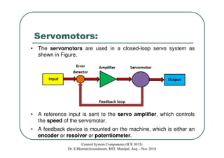
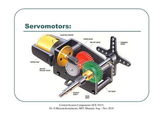
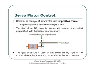
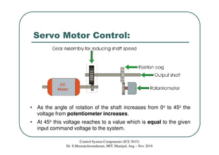
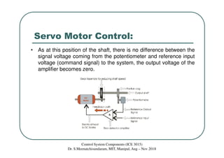
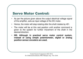
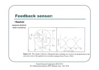
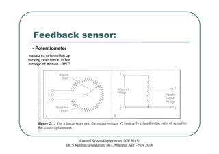
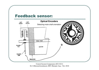
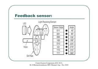

The document discusses servomotors, which are motors used in closed-loop control systems. Servomotors consist of a motor, feedback sensor, and control circuitry. The feedback sensor constantly monitors the motor's position and sends signals to compare with the desired position. If a difference is detected, an error signal is sent to adjust the motor until the desired position is reached. Common feedback sensors include potentiometers, resolvers, and encoders. Continuous rotation servomotors can control speed and direction but not precise position.