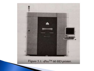
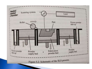
POWDER-BASED RAPID PROTOTYPING
SYSTEMS
3D Systems' SLS
SLM Solutions' Selective Laser Melting
3D Systems' CJP Technology
BeAM's LMD Systems
Arcam's Electron Beam Melting
DMG MORI's Hybrid AM
ExOne's Digital Part Materialisation
HP's Multi Jet FusionTM
 Powder is the basic medium for printing.
 Selective Laser Sintering (SLS) is similar to the
liquid-based AM systems.
 They generally have a laser to "draw” the
part layer-by-layer, but the medium used for
building the model is a powder instead of
photocurable resin.
 3D Systems SLS was found by Charles W. Hull
and Raymond S. Freed in 1986 commercialising
the SLS systems.
 Company that first introduced the SLS
technology is DTM in August 2001.
 It is patented at University of Texas.
 Its Head office is in USA.
 The current generation consists of the ProX 500 and SPro
series printers.
 The ProX 500 is the latest printer developed by
3D Systems with SLS technology.
 It is designed to increase the productivity and precision of
the machine.
 It uses DuraForm ProX™ materials to produce high-quality
prototypes and parts in various areas.

Furthermore, the sProTM SLS series offers several different
models to achieve different quality and print speed.
 The SLS process is based on the following two
principles:

(1) Parts are built by sintering when a CO2 laser
beam hit a thin layer of powdered material. The
interaction of the laser beam with the powder
raises the temperature of the powder prior to its
melting point, resulting in particle bonding,
fusing the particles to themselves and the
previous layer to form a solid. This is the basic
principle of sinter bonding.
 (2) The building of the part is done layer-by-
layer. Each layer of the building process
contains the cross sections of one or many
parts. The next layer is then built directly on
top of the sintered layer after an additional
layer of powder is deposited via a roller
mechanism.

The SLS process creates 3D objects, layer-by-
layer, from computer aided design (CAD) data
using powdered materials with heat generated
by a CO2 laser within the SLS machine.
 CAD data files in the STL file format are first
transferred to the SLS machine systems where
they are sliced.
 From this point, the SLS process begins and
operates as follows:
 A thin layer of heat-fusible powder is deposited onto the
part- building chamber.

The bottom-most cross-sectional slice of the CAD part to
be fabricated is selectively "drawn” (or scanned) on the
layer of powder by a CO2 laser.
 The interaction of the laser beam with the powder elevates
the temperature to glass-transition temperature, fusing
the powder particles to form a solid mass.
 The intensity of the laser beam is modulated to sinter the
powder only in areas defined by the part's geometry.
 Surrounding powder remains a loose compact
and serves as natural supports.
 When the cross section is completely “drawn”,
an additional layer of powder is deposited via
a roller mechanism on top of the previously
scanned layer.

 This prepares the next layer for scanning.
 As SLS materials are in powdered form, the
powder that is not melted or fused during
processing serves as a customised, inherent
built-in support structure.
 Thus, there is no need to create additional
support structures within the CAD design and,
therefore, no post-build removal
of these supports is required.
 After the SLS process, the part is removed
prototype built.
 The packing density of particles during
sintering affects the part density.
 Generally, the higher the packing density,
the better the mechanical properties can be
expected.
 In the process of sinter bonding, particles in each
successive layer are fused to each other and to the previous
layer by raising their temperature with the laser beam to
above the glass-transition temperature.
 The glass- transition temperature is the temperature at
which the material begins to soften from a solid state to a
jelly-like condition.
 This often occurs just prior to the melting temperature at
which the material will be in a molten or liquid state.
 As a result, the particles begin to soften and deform owing
to its weight and cause the surfaces in contact with other
particles or solid to deform and fuse together at these
contact surfaces.
 One major advantage of sintering over melting
and fusing is that it joins powder particles into
a solid part without going into the liquid
phase, thus avoiding the distortions caused by
the flow of molten material during fusion.
 After cooling powder particles are connected
in a matrix that has approximately the density
of particle material.
 As the sintering process requires the machine to bring the
temperature of the particles to the glass-transition temperature,
the energy required is considerably high.

 The energy required to sinter bond a similar layer thickness of
material is approximately between 300 and 500 times higher than
that required for photopolymerisation.
 This high-power requirement can be reduced by using auxiliary
heaters to raise the powder temperature to just below the sintering
temperature during the sintering process.
 However, an inert gas environment is needed to prevent oxidation
or explosion of the fine powder particles.
 Cooling is also necessary for the chamber gas,
(1) Sinterstation Pro SLS System. Manufactures
parts from 3D CAD data.
(2) Rapid Change Module (RCM). Build module
mounted on wheels for quick and easy transfer
between the Sinterstation, the Offline Thermal
Station (OTS) and the Break Out Station (BOS).
(3) Nitrogen Generator. Delivers a continuous
supply of nitrogen to the prototype built.
 (4) OTS. Pre-heats the RCM before it is loaded
into the SLS system and controls the RCM
cool down process after a build has been
completed.

(5) BOS. The built parts are extracted from
the powder cake here. The non-sintered
powder automatically gets sifted and
transferred to the IRS.
 (6) Integrated Recycling Station (IRS). The IRS
automatically blends recycled and new powder.
 The mixed powder is automatically transferred to
the SLS system.

(7) Intelligent Powder Cartridge (IPC). New
powder is loaded into the IRS from a returnable
powder cartridge. When the IPC is connected to
the IRS, electronic material information is
automatically transferred to the SLS system.
 The software and system controller for Sinterstation HiQ TM
Series SLS System includes the proprietary SLS system software
running on Microsoft's Windows XP operating system.
 The software that comes with Sinterstation® Pro SLS® system
includes the following:
Build Setup and Sinter (included)
SinterscanTM (optional) software provides more uniform
properties in x- and y-directions and improved surface finish.
RealMonitorTM (optional) software provides advanced
monitoring and tracking capabilities.

The materials used in SLS® system can be broadly classified into
two groups:
 DuraForm materials
 CastForm materials

The DuraForm® group consists of the following materials:
 DuraForm® GF material
 DuraForm® PA material
 DuraForm® EX material
DuraForm® Flex plastic
 DuraForm® FR 100 material
 DuraForm® HST Composite material
 DuraForm® ProXTM material
 DuraForm® AF plastic
 DuraForm GF plastic.
 These are glass-filled polyamide (nylon) material for tough real-world
physical testing and functional applications.
 The features of the material are as follows:
 Excellent mechanical stiffness
 Elevated temperature resistance
 Dimensional stability
 Easy-to-process
 relatively good surface finish

Applications for the material
 housings and enclosures
consumer sporting goods
 low-to-medium batch size manufacturing
 functional prototypes
 parts requiring stiffness
 Thermally stressed parts.
 DuraForm PA plastic. These are durable polyamide (nylon) material for
general physical testing and functional applications.
The features of the material are as follows:
 Excellent surface resolution and feature detail
 Easy-to-process
 Compliant with USP class VI testing
 Compatible with autoclave sterilisation
 Good chemical resistance
 Low moisture absorption
 Applications for the material
 producing complex thin wall ductwork, for example motorsports, aerospace, impellers
and connectors, consumer sporting goods, vehicle dashboards and grilles, snap-fit
designs, functional prototypes that approach end-use performance properties, medical
applications requiring USP Class VI compliance, parts requiring machining or joining
with adhesives.
 DuraForm EX plastic. These are impact-resistant plastic
offering the toughness of injection-moulded
thermoplastics and are suitable for rapid manufacturing.
They are available in either natural (white) or black
colours.

 Features of the material
Toughness and impact resistance of injection-moulded
ABS and polypropylene.
 Applications for the material
 Complex, thin- walled ductwork, motorsports, aerospace
and unmanned air vehicles (UAVs), snap-fit designs,
hinges, vehicle dashboards, grilles and bumpers.
 DuraForm Flex plastic. This is a thermoplastic
elastomer material with rubber-like flexibility and
functionality.
 Features of the material are as follows: flexible,
durable with good tear resistance,
variability of Shore A hardness using the same
material, good powder recycle characteristics, good
surface finish and feature details.
 The applications for the material include athletic
footwear and equipment, gaskets, hoses and seals,
simulated thermoplastic elastomer, cast urethane,
silicone and rubber parts.
 DuraForm® AF plastic. These are polyamide (nylon)
material with metallic appearance for real-world physical
testing and functional
use.
 Features of the material are as follows:
 Metallic appearance with nice surface finish
 Good powder recycle characteristics,
 Excellent mechanical stiffness,
 Easy-to-process
 Dimensional stability.
 Applications for the material include housings and
enclosures, consumer products, thermally stressed parts
and plastic parts requiring a metallic appearance.
 DuraForm® FR 100 material.
 This is a halogen and antimony-free, flame
retardant engineering plastic. It is suitable for
AM of aerospace parts and parts requiring
UL 94-V-0 compliance.
 DuraForm® HST Composite material.
 This is a fibre reinforced engineering plastic
with high stiffness, strength and temperature
resistance.
 DuraForm ProXTM material. This is an extra-
strong engineered production plastic.
 It is used to produce durable functional
prototypes with superior mechanical
properties.
 It was developed in tandem with ProX 500
printer to print smoother wall surfaces
comparable to injection-moulded part.
 CastForm M PS material. This material directly produces complex
investment casting patterns without tooling.
 Features of this “foundry friendly” material include:
 Foundry wax, low residual ash content (<0.02%),
 Short burnout cycle, easy-to-process plastic
 Good plastic powder recycle characteristics.
 Applications of the material include
 creating complex investment casting patterns,
indirectly producing reactive metals (such as titanium and
magnesium),
near net-shaped components,
 low-melting point metals (such as aluminium, magnesium and zinc),
 ferrous and non-ferrous metals.
Smaller parts can be joined to create very large patterns, which are
sacrificial and expendable.
 (1) Good part stability. Parts are created within a precise controlled
environment. The process and materials provide for functional parts
to be built directly.
(2) Wide range of processing materials. In general, any material in
powder form can be sintered on the SLS. A wide range of materials
including nylon, polycarbonates, metals and ceramics are available
directly from 3D Systems, thus providing flexibility and a wide
scope of functional applications.
.

(3) No part supports required. The system does not require CAD-
developed support structures. This saves the time required for
support structure building and removal
 (4) Little post-processing required. The finish
of the part is reasonably fine and requires
only minimal post-processing such as
particle blasting and sanding.
 (5) No post-curing required. The completed
laser sintered part is generally solid enough
and does not require further curing.
 (6) Advanced software support. The new
version 2.0 software uses a Windows NT-style
graphical user interface (GUI). Apart from the
basic features, it allows for streamlined parts
scaling, advanced non-linear parts scaling,
in-progress part changes and build report
utilities. It is available in different foreign
languages.
 (1) Large physical size of the unit. The system requires
a relatively large space to house it. Apart from this,
additional storage space is required to house the inert
gas tanks that are required for each build.
 (2) High power consumption. The system requires high
power consumption due to the high wattage of the laser
required to sinter the powder particles together.
 (3) Poor surface finish. The as-produced parts tend to
have poorer surface finish due to the relatively large
particle sizes of the powders used.
 (1) Concept models. Physical representations of designs used
to review design ideas, form and style.

(2) Functional models and working prototypes. Parts that can
withstand limited functional testing, or fit and operate within
an assembly.

(3) Polycarbonate (RapidCastingTM) patterns. Patterns
produced using polycarbonate, and then cast in the metal of
choice through the standard investment casting process.
These build faster than wax patterns and are ideally suited for
designs with thin walls and fine features. These patterns are
also durable and heat resistant
 (4) Metal tools (RapidToolTM). Direct rapid
prototype of tools of moulds for small or
short production runs.

(5) Aerospace ducting. With parts and
components with high precision and high
strength produced by SLS® in ducting system,
AM's products are already been used in many
different aircrafts.
 Primary research continues to focus on new
and advanced materials while further
improving and refining SLS process, software
and system.

Currently, ProX 500 is one of the latest SLS
machines while 3D Systems is still working to
improve the build volume as well as to reduce
the cost.

SLS IN RP

  • 1.
  • 2.
    3D Systems' SLS SLMSolutions' Selective Laser Melting 3D Systems' CJP Technology BeAM's LMD Systems Arcam's Electron Beam Melting DMG MORI's Hybrid AM ExOne's Digital Part Materialisation HP's Multi Jet FusionTM
  • 4.
     Powder isthe basic medium for printing.  Selective Laser Sintering (SLS) is similar to the liquid-based AM systems.  They generally have a laser to "draw” the part layer-by-layer, but the medium used for building the model is a powder instead of photocurable resin.
  • 5.
     3D SystemsSLS was found by Charles W. Hull and Raymond S. Freed in 1986 commercialising the SLS systems.  Company that first introduced the SLS technology is DTM in August 2001.  It is patented at University of Texas.  Its Head office is in USA.
  • 6.
     The currentgeneration consists of the ProX 500 and SPro series printers.  The ProX 500 is the latest printer developed by 3D Systems with SLS technology.  It is designed to increase the productivity and precision of the machine.  It uses DuraForm ProX™ materials to produce high-quality prototypes and parts in various areas.  Furthermore, the sProTM SLS series offers several different models to achieve different quality and print speed.
  • 11.
     The SLSprocess is based on the following two principles:  (1) Parts are built by sintering when a CO2 laser beam hit a thin layer of powdered material. The interaction of the laser beam with the powder raises the temperature of the powder prior to its melting point, resulting in particle bonding, fusing the particles to themselves and the previous layer to form a solid. This is the basic principle of sinter bonding.
  • 12.
     (2) Thebuilding of the part is done layer-by- layer. Each layer of the building process contains the cross sections of one or many parts. The next layer is then built directly on top of the sintered layer after an additional layer of powder is deposited via a roller mechanism.
  • 14.
     The SLS processcreates 3D objects, layer-by- layer, from computer aided design (CAD) data using powdered materials with heat generated by a CO2 laser within the SLS machine.  CAD data files in the STL file format are first transferred to the SLS machine systems where they are sliced.  From this point, the SLS process begins and operates as follows:
  • 15.
     A thinlayer of heat-fusible powder is deposited onto the part- building chamber.  The bottom-most cross-sectional slice of the CAD part to be fabricated is selectively "drawn” (or scanned) on the layer of powder by a CO2 laser.  The interaction of the laser beam with the powder elevates the temperature to glass-transition temperature, fusing the powder particles to form a solid mass.  The intensity of the laser beam is modulated to sinter the powder only in areas defined by the part's geometry.
  • 16.
     Surrounding powderremains a loose compact and serves as natural supports.  When the cross section is completely “drawn”, an additional layer of powder is deposited via a roller mechanism on top of the previously scanned layer.   This prepares the next layer for scanning.
  • 17.
     As SLSmaterials are in powdered form, the powder that is not melted or fused during processing serves as a customised, inherent built-in support structure.  Thus, there is no need to create additional support structures within the CAD design and, therefore, no post-build removal of these supports is required.  After the SLS process, the part is removed prototype built.
  • 18.
     The packingdensity of particles during sintering affects the part density.  Generally, the higher the packing density, the better the mechanical properties can be expected.
  • 19.
     In theprocess of sinter bonding, particles in each successive layer are fused to each other and to the previous layer by raising their temperature with the laser beam to above the glass-transition temperature.  The glass- transition temperature is the temperature at which the material begins to soften from a solid state to a jelly-like condition.  This often occurs just prior to the melting temperature at which the material will be in a molten or liquid state.  As a result, the particles begin to soften and deform owing to its weight and cause the surfaces in contact with other particles or solid to deform and fuse together at these contact surfaces.
  • 20.
     One majoradvantage of sintering over melting and fusing is that it joins powder particles into a solid part without going into the liquid phase, thus avoiding the distortions caused by the flow of molten material during fusion.  After cooling powder particles are connected in a matrix that has approximately the density of particle material.
  • 21.
     As thesintering process requires the machine to bring the temperature of the particles to the glass-transition temperature, the energy required is considerably high.   The energy required to sinter bond a similar layer thickness of material is approximately between 300 and 500 times higher than that required for photopolymerisation.  This high-power requirement can be reduced by using auxiliary heaters to raise the powder temperature to just below the sintering temperature during the sintering process.  However, an inert gas environment is needed to prevent oxidation or explosion of the fine powder particles.  Cooling is also necessary for the chamber gas,
  • 22.
    (1) Sinterstation ProSLS System. Manufactures parts from 3D CAD data. (2) Rapid Change Module (RCM). Build module mounted on wheels for quick and easy transfer between the Sinterstation, the Offline Thermal Station (OTS) and the Break Out Station (BOS). (3) Nitrogen Generator. Delivers a continuous supply of nitrogen to the prototype built.
  • 23.
     (4) OTS.Pre-heats the RCM before it is loaded into the SLS system and controls the RCM cool down process after a build has been completed.  (5) BOS. The built parts are extracted from the powder cake here. The non-sintered powder automatically gets sifted and transferred to the IRS.
  • 24.
     (6) IntegratedRecycling Station (IRS). The IRS automatically blends recycled and new powder.  The mixed powder is automatically transferred to the SLS system.  (7) Intelligent Powder Cartridge (IPC). New powder is loaded into the IRS from a returnable powder cartridge. When the IPC is connected to the IRS, electronic material information is automatically transferred to the SLS system.
  • 25.
     The softwareand system controller for Sinterstation HiQ TM Series SLS System includes the proprietary SLS system software running on Microsoft's Windows XP operating system.  The software that comes with Sinterstation® Pro SLS® system includes the following: Build Setup and Sinter (included) SinterscanTM (optional) software provides more uniform properties in x- and y-directions and improved surface finish. RealMonitorTM (optional) software provides advanced monitoring and tracking capabilities.
  • 26.
     The materials usedin SLS® system can be broadly classified into two groups:  DuraForm materials  CastForm materials  The DuraForm® group consists of the following materials:  DuraForm® GF material  DuraForm® PA material  DuraForm® EX material DuraForm® Flex plastic  DuraForm® FR 100 material  DuraForm® HST Composite material  DuraForm® ProXTM material  DuraForm® AF plastic
  • 27.
     DuraForm GFplastic.  These are glass-filled polyamide (nylon) material for tough real-world physical testing and functional applications.  The features of the material are as follows:  Excellent mechanical stiffness  Elevated temperature resistance  Dimensional stability  Easy-to-process  relatively good surface finish  Applications for the material  housings and enclosures consumer sporting goods  low-to-medium batch size manufacturing  functional prototypes  parts requiring stiffness  Thermally stressed parts.
  • 28.
     DuraForm PAplastic. These are durable polyamide (nylon) material for general physical testing and functional applications. The features of the material are as follows:  Excellent surface resolution and feature detail  Easy-to-process  Compliant with USP class VI testing  Compatible with autoclave sterilisation  Good chemical resistance  Low moisture absorption  Applications for the material  producing complex thin wall ductwork, for example motorsports, aerospace, impellers and connectors, consumer sporting goods, vehicle dashboards and grilles, snap-fit designs, functional prototypes that approach end-use performance properties, medical applications requiring USP Class VI compliance, parts requiring machining or joining with adhesives.
  • 29.
     DuraForm EXplastic. These are impact-resistant plastic offering the toughness of injection-moulded thermoplastics and are suitable for rapid manufacturing. They are available in either natural (white) or black colours.   Features of the material Toughness and impact resistance of injection-moulded ABS and polypropylene.  Applications for the material  Complex, thin- walled ductwork, motorsports, aerospace and unmanned air vehicles (UAVs), snap-fit designs, hinges, vehicle dashboards, grilles and bumpers.
  • 30.
     DuraForm Flexplastic. This is a thermoplastic elastomer material with rubber-like flexibility and functionality.  Features of the material are as follows: flexible, durable with good tear resistance, variability of Shore A hardness using the same material, good powder recycle characteristics, good surface finish and feature details.  The applications for the material include athletic footwear and equipment, gaskets, hoses and seals, simulated thermoplastic elastomer, cast urethane, silicone and rubber parts.
  • 31.
     DuraForm® AFplastic. These are polyamide (nylon) material with metallic appearance for real-world physical testing and functional use.  Features of the material are as follows:  Metallic appearance with nice surface finish  Good powder recycle characteristics,  Excellent mechanical stiffness,  Easy-to-process  Dimensional stability.  Applications for the material include housings and enclosures, consumer products, thermally stressed parts and plastic parts requiring a metallic appearance.
  • 32.
     DuraForm® FR100 material.  This is a halogen and antimony-free, flame retardant engineering plastic. It is suitable for AM of aerospace parts and parts requiring UL 94-V-0 compliance.
  • 33.
     DuraForm® HSTComposite material.  This is a fibre reinforced engineering plastic with high stiffness, strength and temperature resistance.
  • 34.
     DuraForm ProXTMmaterial. This is an extra- strong engineered production plastic.  It is used to produce durable functional prototypes with superior mechanical properties.  It was developed in tandem with ProX 500 printer to print smoother wall surfaces comparable to injection-moulded part.
  • 35.
     CastForm MPS material. This material directly produces complex investment casting patterns without tooling.  Features of this “foundry friendly” material include:  Foundry wax, low residual ash content (<0.02%),  Short burnout cycle, easy-to-process plastic  Good plastic powder recycle characteristics.  Applications of the material include  creating complex investment casting patterns, indirectly producing reactive metals (such as titanium and magnesium), near net-shaped components,  low-melting point metals (such as aluminium, magnesium and zinc),  ferrous and non-ferrous metals. Smaller parts can be joined to create very large patterns, which are sacrificial and expendable.
  • 36.
     (1) Goodpart stability. Parts are created within a precise controlled environment. The process and materials provide for functional parts to be built directly. (2) Wide range of processing materials. In general, any material in powder form can be sintered on the SLS. A wide range of materials including nylon, polycarbonates, metals and ceramics are available directly from 3D Systems, thus providing flexibility and a wide scope of functional applications. .  (3) No part supports required. The system does not require CAD- developed support structures. This saves the time required for support structure building and removal
  • 37.
     (4) Littlepost-processing required. The finish of the part is reasonably fine and requires only minimal post-processing such as particle blasting and sanding.  (5) No post-curing required. The completed laser sintered part is generally solid enough and does not require further curing.
  • 38.
     (6) Advancedsoftware support. The new version 2.0 software uses a Windows NT-style graphical user interface (GUI). Apart from the basic features, it allows for streamlined parts scaling, advanced non-linear parts scaling, in-progress part changes and build report utilities. It is available in different foreign languages.
  • 39.
     (1) Largephysical size of the unit. The system requires a relatively large space to house it. Apart from this, additional storage space is required to house the inert gas tanks that are required for each build.  (2) High power consumption. The system requires high power consumption due to the high wattage of the laser required to sinter the powder particles together.  (3) Poor surface finish. The as-produced parts tend to have poorer surface finish due to the relatively large particle sizes of the powders used.
  • 40.
     (1) Conceptmodels. Physical representations of designs used to review design ideas, form and style.  (2) Functional models and working prototypes. Parts that can withstand limited functional testing, or fit and operate within an assembly.  (3) Polycarbonate (RapidCastingTM) patterns. Patterns produced using polycarbonate, and then cast in the metal of choice through the standard investment casting process. These build faster than wax patterns and are ideally suited for designs with thin walls and fine features. These patterns are also durable and heat resistant
  • 41.
     (4) Metaltools (RapidToolTM). Direct rapid prototype of tools of moulds for small or short production runs.  (5) Aerospace ducting. With parts and components with high precision and high strength produced by SLS® in ducting system, AM's products are already been used in many different aircrafts.
  • 42.
     Primary researchcontinues to focus on new and advanced materials while further improving and refining SLS process, software and system.  Currently, ProX 500 is one of the latest SLS machines while 3D Systems is still working to improve the build volume as well as to reduce the cost.