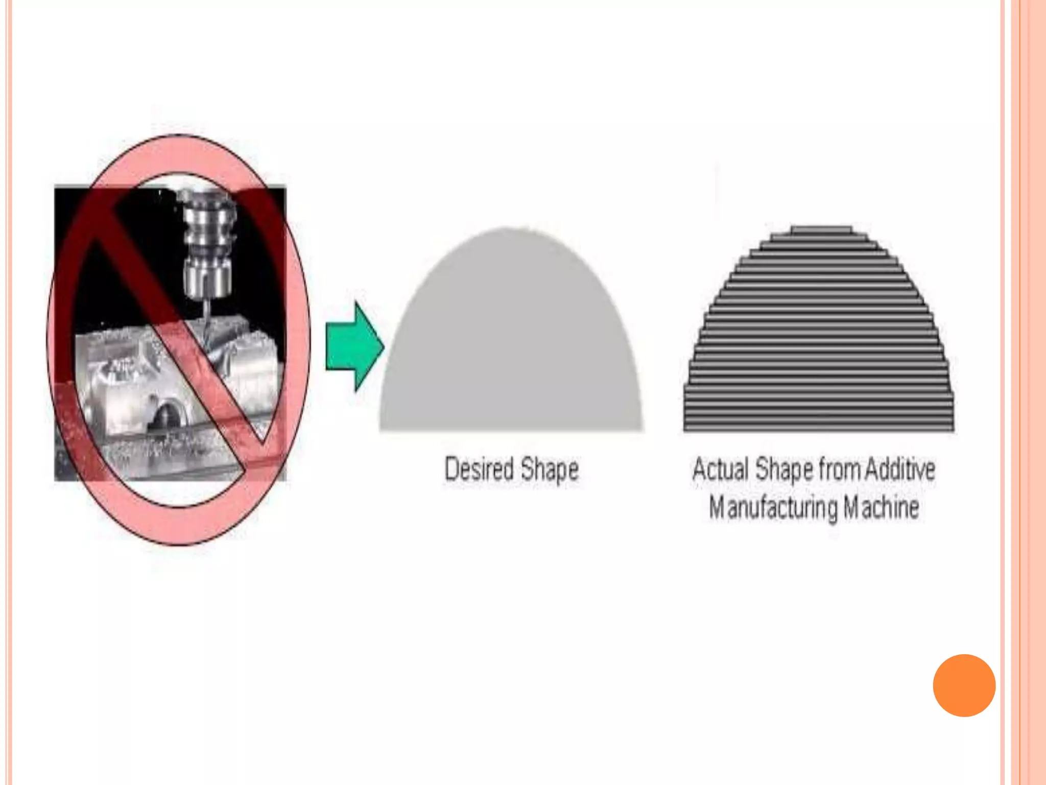
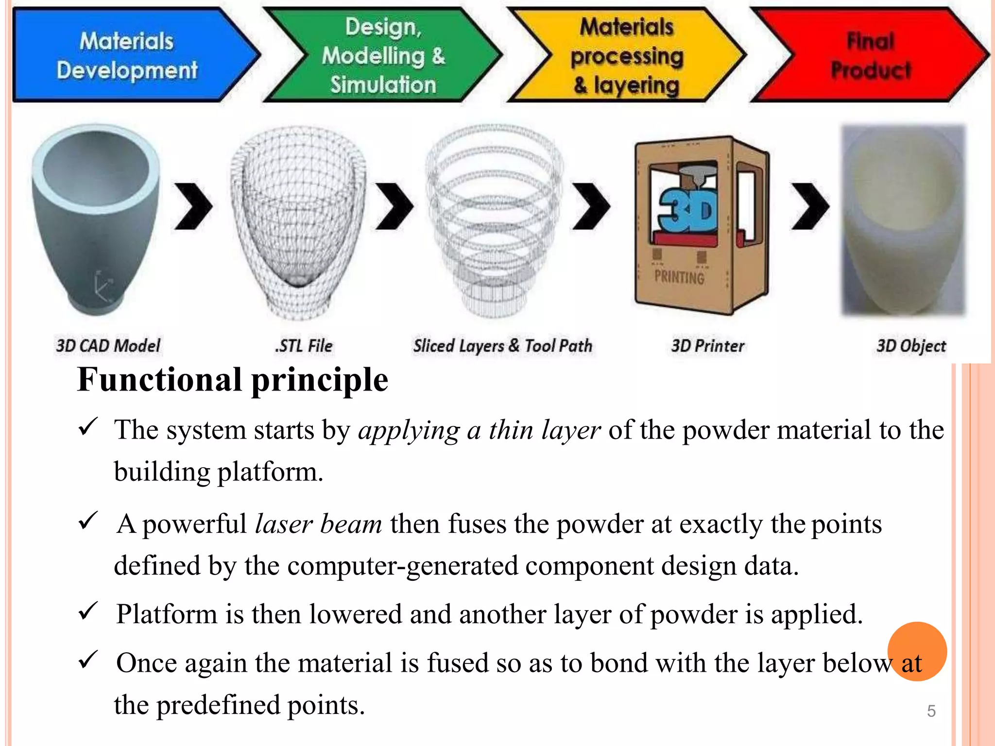
The document provides an introduction to additive manufacturing (AM) including definitions, principles, types of prototypes, advantages, and commonly used terms. It discusses how AM works by building 3D objects layer by layer from a digital file. Key points covered include the 7 main AM processes classified by ISO/ASTM, the history and development of stereolithography, and benefits of AM for designers, engineers, and manufacturing.
Selective Laser Sintering is one of the most used processes of Rapid Prototyping. It is a powder based process where powder of different metals/materials get sintered by LASER.
this short ppt gives you a rough idea about the additive manufacturing process of stereolithography. This process is apart of 3d printing technologies around us. Also included is link to a video that will help you further.
The term “additive manufacturing” references technologies that grow three-dimensional objects one superfine layer at a time. Each successive layer bonds to the preceding layer of melted or partially melted material. Objects are digitally defined by computer-aided-design (CAD) software that is used to create .stl files that essentially "slice" the object into ultra-thin layers. This information guides the path of a nozzle or print head as it precisely deposits material upon the preceding layer. Or, a laser or electron beam selectively melts or partially melts in a bed of powdered material. As materials cool or are cured, they fuse together to form a three-dimensional object.
This power point presentation gives the introduction about DMLS process (Direct Metal Laser sintering) and Direct Metal 20 (DM20) material. It also illustrates DMLS process and applications of DMLS.
Additive manufacturing (AM) or 3D printing is maturing rapidly as a viable solution of make optimized parts for “real engineering” applications. The freedom of design that is achievable using AM process is un parallel in terms of reducing structural weight, reducing material cost, generating complex shapes and connections and introducing directional properties in a component. However, understanding of AM process and utilizing process parameters to optimize a design comes with many challenges. Currently, one of the emphasize is to use physics based realistic simulation to replicate the AM process numerically and relate process parameters to the concept of functional generative design that relates design with manufacturing process.
Current work, through a typical build example, discusses an integrated numerical solution on a digital platform that involves the following.
Generative Design involving topology optimization that creates parts in context of the manufacturing process and automatically generate variants of conceptual and detailed organic shapes that helps make informed business decisions based on physics-based analytic tools. Process planning that defines and customizes manufacturing environment including nesting parts automatically on the build tray, designing and generating optimal support structures, and creating machine specific slicing and scan path which is ready for print. Process simulation that automatically includes machine inputs for energy, material and supports into the simulation at layer, part and build levels for any additive manufacturing process and accurately predicts part distortions, residual stresses and as-built material behavior. Finally, the platform involves post processing to perform shape optimization where simulation is used to guide support-structure strategy for enhanced build yield, compensate distortion effects without the need to redesign the product tooling, produce high-quality morphed surface geometry with unchanged topology, and perform final in-service performance validations of manufactured part.
FDM Process introduction (A part of Additive Manufacturing Technique OR Commonly Known as 3D Printing). 3D printing is an evolved manufacturing technique; it is comparatively better than conventional substractive manufacturing. There is minimum wastage of material because material is added only at those locations where it is required. To make 3D model you need a 3D printer and feeding material and obviously power source. Any thermoplastic material whose melting temperature lies in the range of 150-240 deg. C can be used in FDM based 3D printing.
BAHIR DAR UNIVERSITYBAHIR DAR INSTITUTE OF TECHNOLOGY (BiT)FACULTY OF MECHANICAL AND INDUSTRIAL ENGINEERING Rapid Prototyping & Reverse Engineering [MEng6123]
Rapid Prototyping Techniques
They can be categorized by material: photopolymer, thermoplastic, and adhesives.
Photopolymer systems start with a liquid resin, which is then solidified by exposure to a specific wavelength of light.
Thermoplastic systems begin with a solid material, which is then melted and fuses upon cooling.
The adhesive systems use a binder to connect the primary construction material
Rapid Prototyping Techniques
The initial state of material can come in either
solid, liquid or powder state
The current range materials include
paper, polymer, nylon, wax, resins, metals and ceramics.
Liquid Based RP Systems
Solidification of a Liquid Polymer
These process involve the solidification of a resin via electromagnetic radiation
There are different processes in this category
Stereolithography (SL)
Liquid Thermal Polymerization (LTP)
Beam Interference Solidification (BIS)
Solid Ground Curing (SGC)
Objet Quadra Process (Objet)
Holographic Interference Solidification
Liquid Based RP Systems
Stereolithography (SL)
Principle of Operation
Patented in 1986,
Started the RP revolution
Developed by 3D Systems, Inc.
Most popular RP methods.
The technique builds 3D models from liquid photosensitive polymers that solidify when exposed to ultraviolet light.
Builds plastic parts a layer at a time by tracing a laser beam on the surface of a vat of liquid photopolymer.
The liquid photopolymer, quickly solidifies wherever the laser beam strikes the surface of the liquid
Additive manufacturing 3D Printing technologySTAY CURIOUS
Additive manufacturing 3D Printing
3D printing is the process of building an object one thin layer at a time. It is fundamentally additive rather than subtractive in nature. To many, 3D printing is the singular production of often-ornate objects on a desktop printer.
CAD/CAM/CIM (18ME72) Module-5 Part-A as per VTU
Additive Manufacturing Systems: Basic principles of additive manufacturing, slicing CAD models for AM, advantages and limitations of AM technologies, Additive manufacturing processes: Photo polymerization, material jetting, binder jetting, material extrusion, Powder bed sintering techniques, sheet lamination, direct energy deposition techniques, applications of AM.
Additive manufacturing (AM) or additive layer manufacturing (ALM) is the industrial production name for 3D printing, a computer controlled process that creates three dimensional objects by depositing materials, usually in layers.
AM is a rapidly growing field that is having an impact on multiple industries by simplifying the process to go from a 3D model to a finished product.
In contrast to conventional manufacturing processes, AM fabricates objects by adding materials as required which eliminates the necessity of subtracting materials (by means of machining, milling, carving, etc.) to obtain desired shapes.
AM can advantageously fabricate complex geometries with no part-specific tooling and much less waste material.
In the construction sector, architectural models have been created with AM methods for more than a decade.
Recent years have seen a vast increase in research on printing methods for building components.
AM allows building companies to produce geometrically complex structures, to vary materials within a component according to its functions, and to automate the construction process starting from a digital model.
The technology can bring significant benefits to the construction industry in terms of increased customization, reduced construction time, reduced manpower, and construction cost.
I have been trying to get the job description of the day and night I have to do with my friends and I have a question regarding this matter what I am saying I am a student in a different perspective on how the government to be able to get the job description of the day and time again for your time and it will take
Harnessing WebAssembly for Real-time Stateless Streaming PipelinesChristina Lin
Traditionally, dealing with real-time data pipelines has involved significant overhead, even for straightforward tasks like data transformation or masking. However, in this talk, we’ll venture into the dynamic realm of WebAssembly (WASM) and discover how it can revolutionize the creation of stateless streaming pipelines within a Kafka (Redpanda) broker. These pipelines are adept at managing low-latency, high-data-volume scenarios.
Low power architecture of logic gates using adiabatic techniquesnooriasukmaningtyas
The growing significance of portable systems to limit power consumption in ultra-large-scale-integration chips of very high density, has recently led to rapid and inventive progresses in low-power design. The most effective technique is adiabatic logic circuit design in energy-efficient hardware. This paper presents two adiabatic approaches for the design of low power circuits, modified positive feedback adiabatic logic (modified PFAL) and the other is direct current diode based positive feedback adiabatic logic (DC-DB PFAL). Logic gates are the preliminary components in any digital circuit design. By improving the performance of basic gates, one can improvise the whole system performance. In this paper proposed circuit design of the low power architecture of OR/NOR, AND/NAND, and XOR/XNOR gates are presented using the said approaches and their results are analyzed for powerdissipation, delay, power-delay-product and rise time and compared with the other adiabatic techniques along with the conventional complementary metal oxide semiconductor (CMOS) designs reported in the literature. It has been found that the designs with DC-DB PFAL technique outperform with the percentage improvement of 65% for NOR gate and 7% for NAND gate and 34% for XNOR gate over the modified PFAL techniques at 10 MHz respectively.
Online aptitude test management system project report.pdfKamal Acharya
The purpose of on-line aptitude test system is to take online test in an efficient manner and no time wasting for checking the paper. The main objective of on-line aptitude test system is to efficiently evaluate the candidate thoroughly through a fully automated system that not only saves lot of time but also gives fast results. For students they give papers according to their convenience and time and there is no need of using extra thing like paper, pen etc. This can be used in educational institutions as well as in corporate world. Can be used anywhere any time as it is a web based application (user Location doesn’t matter). No restriction that examiner has to be present when the candidate takes the test.
Every time when lecturers/professors need to conduct examinations they have to sit down think about the questions and then create a whole new set of questions for each and every exam. In some cases the professor may want to give an open book online exam that is the student can take the exam any time anywhere, but the student might have to answer the questions in a limited time period. The professor may want to change the sequence of questions for every student. The problem that a student has is whenever a date for the exam is declared the student has to take it and there is no way he can take it at some other time. This project will create an interface for the examiner to create and store questions in a repository. It will also create an interface for the student to take examinations at his convenience and the questions and/or exams may be timed. Thereby creating an application which can be used by examiners and examinee’s simultaneously.
Examination System is very useful for Teachers/Professors. As in the teaching profession, you are responsible for writing question papers. In the conventional method, you write the question paper on paper, keep question papers separate from answers and all this information you have to keep in a locker to avoid unauthorized access. Using the Examination System you can create a question paper and everything will be written to a single exam file in encrypted format. You can set the General and Administrator password to avoid unauthorized access to your question paper. Every time you start the examination, the program shuffles all the questions and selects them randomly from the database, which reduces the chances of memorizing the questions.
2. INTRODUCTION
The competition in the world market for manufactured
products has intensified tremendously in recent years.
It has become important, if not vital, for new products to
reach the market as early as possible, before the
competitors .
3. INTRODUCTION
To bring products to the market swiftly, many of the
processes involved in the design, test, manufacture and
market of the products have been squeezed, both in terms
of time and material resources.
4. INTRODUCTION
Many of the tools and effective approaches have been
evolved in the market to bring the product swiftly in to
the market.
These tools are almost technology driven involving
computers.
As a result there is so much advancement in
technologies over last few decades.
5. DEFINITION
The process of joining materials to make objects from three-
dimensional (3D) model data, usually layer by layer.
Commonly known as “3D printing”
AM uses an additive process
6.
7. Functional principle
The system starts by applying a thin layer of the powder material to the
building platform.
A powerful laser beam then fuses the powder at exactly the points
defined by the computer-generated component design data.
Platform is then lowered and another layer of powder is applied.
Once again the material is fused so as to bond with the layer below at
the predefined points. 5
8. DEFINITION OF PROTOTYPE
According to Oxford Advanced Learners Dictionary
of current English
A prototype is the first or original example of
something that has been or will be copied or
developed
It is a model or preliminary version
General definition in design terms would be an
approximation of a product or system or its
components in some form for a definite purpose in
its implementation
9. PROTOTYPES ARE USED FOR THE FOLLOWING
PURPOSES
Experimentation and learning while designing
Testing and proofing of ideas and concepts
Communication and interaction among design teams
Synthesis and integration of the entire product concept
10. CLASSIFICATION OF PROTOTYPES
Implementation:
Complete prototypes will model most of the characteristics
of the final product.
The prototypes are usually full-scale and they are also
usually fully functional.
11. CLASSIFICATION OF PROTOTYPES
Prototypes can be partially functional in nature.
These prototypes are either needed to study and
investigate special problems associated with a single
component or sub-assembly, or they are needed to study
and validate a concept that requires close attention.
13. CLASSIFICATION OF PROTOTYPES
FORM:
Physical prototypes are tangible, and are built for
the purpose of testing, experimentation or aesthetic
and human factors evaluation.
Physical prototypes can be manufactured using AM
techniques, or other methods which tend to be less
sophisticated, craft-based and largely labour-
intensive.
An example is the mock-up of a mobile phone.
14. CLASSIFICATION OF PROTOTYPES
Form:
Virtual prototypes are non-tangible, and they are used when the
physical prototype are too large, too expensive or too time-consuming
to produce.
Virtual prototypes are based purely upon the assumed principles or
science at that point in time, and are completely unable to predict any
unexpected phenomenon. Nowadays, virtual prototypes can be
stressed, tested, analysed and modified as if they were physical
prototypes.
An example is the visualisation of airflow over an aircraft wing.
15. CLASSIFICATION OF PROTOTYPES
Degree of approximation:
Prototypes can be very rough representations of
the intended final product.
The prototype is therefore used for testing and
studying certain problems that can arise from
product development.
16. CLASSIFICATION OF PROTOTYPES
Alternatively the prototype can be an exact full-scale
representation of the product, modelling every aspect
of the product.
This type of prototype becomes more and more important
towards the end-stage of the product development
process.
17. FUNDAMENTALS OF AM
1. A model or component is modelled on a Computer-
Aided Design and Computer-Aided Manufacturing
(CAD/CAM) system.
The model, which describes the physical part to be built,
must be represented as closed surfaces which
unambiguously define an enclosed volume. This means
that the data must specify the inside, the outside and the
boundary of the model.
18. FUNDAMENTALS OF AM
2. The solid or surface model to be built is next converted
into a format called the .STL file format which originated
from 3D Systems.
The STL file format approximates the surfaces of the
model using the simplest of polygons and triangles.
Some AM systems also accept data in the IGES (Initial
Graphics Exchange Specification)
format, provided it is of the correct "flavour".
19. FUNDAMENTALS OF AM
3. A computer program analyses a STL file that defines the
model to be fabricated and “slices” the model into cross
sections.
The cross sections are systematically recreated through
the solidification of either liquids or powders and then
combined to form a 3D model.
Another possibility is that the cross sections are already
thin, solid laminations and these thin laminations are glued
together with adhesives to form a 3D model.
20. FOUR KEY ASPECTS OF AM
INPUT
METHOD
MATERIAL
APPLICATIONS
21. INPUT
Input refers to the electronic information required to
describe the object in 3D.
There are two possible starting points —
a computer model
a physical model or part.
The computer model created by a CAD system can be
either a surface model or a solid model.
.
22. INPUT
On the other hand, 3D data from the physical model is not
so straightforward.
It requires data acquisition through a method known as
reverse engineering.
Equipment, such as coordinate measuring machines
(CMM) or laser digitisers, are used to capture data points
of the physical model, usually in a raster
format, and then to “reconstruct” it in a CAD system
23. METHOD
They are currently more than 50 vendors for AM systems
The method employed by each vendor can be generally
classified into the following categories:
(1) Photo-curing
(2) Cutting and joining
(3) Melting and solidifying or fusing
(4) Joining or binding
.
24. MATERIAL
The raw materials can come in one of the following
forms:
Solid, Liquid or Powder state.
Solid materials come in various forms such as pellets,
wire or laminates.
The current range of materials includes paper,
polymers, wax, resins, metals and ceramics.
25. APPLICATIONS
Most of the AM parts are finished or touched up before they
are used for their intended applications.
Applications can be grouped into
(1) design,
(2) engineering analysis and planning
(3) manufacturing and tooling.
Aerospace, automotive, biomedical, consumer,
electrical and electronic products.
27. HISTORICAL DEVELOPMENT
In 1987, the first commercial AM system, stereolithography
apparatus (SLA)-1, was launched by 3D Systems in the United
States.
It worked on the principle of stereolithography (STL) and for the
first time enabled users to generate a physical object from
digital data.
The invention of AM technology was a "watershed event”
because of the tremendous time saved by not machining parts,
especially for complicated and difficult-to-produce models.
Since then, other new AM technologies have been
commercialised, including Fused Deposition Modelling (FDM)
and Selective Deposition Lamination (SDL)
in 1991, as well as Selective Laser Sintering (SLS) in 1992.
28. HISTORICAL DEVELOPMENT
In 1993, Soligen brought Direct Shell Production Casting
to the market and 3D Systems also introduced QuickCast
(a method of producing indirect tooling from AM), as the
potential savings in time and
resources that AM can bring became apparent.
Companies such as General Motors were early adopters
of AM.
They acquired the SLA-250 (the model immediately
following SLA-1) in 1991, and used it for rapid
tooling and prototyping of parts such as cranking motor
nose housings and connector feeder tracks
29. HISTORICAL DEVELOPMENT
3D printers based on technology similar to inkjet printers
began to appear in the market in 1996.
In 1998, Optomec sold its first Laser Engineered Net
Shaping (LENS) metal powder system as the LENS
process was capable of producing fully dense metal parts
with no voids within the metal.
In 1999, selective laser melting (SLM) system was
introduced by Fockele & Schwarze of Germany. Since
2000, there have been many more AM systems entering
the market.
.
30. HISTORICAL DEVELOPMENT
While some companies such as Boeing were already
using AM to produce parts such as electrical boxes,
brackets and environmental control system ducting, the
development of international standards was expected to
help different companies coordinate AM research and
commercialisation efforts and further increase the use of
AM for direct manufacturing
31. ADVANTAGES OF AM
Today's automated, tool-less, pattern-less AM systems
can directly produce functional parts in small production
quantities.
Parts produced in this way usually have an accuracy and
surface finish inferior to those made by machining.
However, some advanced systems are able to
produce near tooling quality parts that are close to or are
in the final shape.
More importantly, the time taken to manufacture any part
— once the design data are available — is short, and can
be a matter of hours.
32. DIRECT BENEFITS
AM has ability to produce physical models of any
complexity in relatively short time.
In the last 40 years, products realised to the market
place have become increasingly complex in shape
and form.
For instance, compare the aesthetically beautiful
car body of today with that of the 1970s.
33. DIRECT BENEFITS
On a relative complexity scale of 1-3 , it can be noted that
from a base of 1 in 1970, this relative complexity index
has increased to about 2 in 1980, approached 3 in the 1990s,
and exceeded 3 after 2000.
However, the relative project completion times
have not correspondingly increased.
It increased from an initial base of about 4 weeks' project
completion time in 1970 to 16 weeks in 1980.
However, with the use of CAD/CAM and computer numerical
control (CNC) technologies, project completion time was
reduced to 8 weeks.
Eventually, AM systems allowed the project manager to
further cut the completion time to less than 2 weeks in 2015.
35. BENEFITS TO PRODUCT DESIGNERS
Product designers can increase part complexity
More organic, sculptured and complex shapes for
functional or aesthetic features can be
accommodated.
They can optimise part design to meet customer
requirements
36. BENEFITS TO PRODUCT DESIGNERS
Product Designers can reduce parts count by
combining features into single-piece parts
With fewer parts, the time spent on tolerance analysis,
selecting fasteners, detailing screw holes and assembly
drawings is greatly reduced.
Product designers can minimise the use of material and
optimise strength/weight ratios without regards to
machining cost.
Finally, they can minimise time-consuming
discussions and evaluations of manufacturing
possibilities.
37. BENEFITS TO MANUFACTURING ENGINEERS
The manufacturer can reduce the labour content of
manufacturing, since part-specific setting up and
programming are eliminated, machining or
casting labour is reduced, and inspection and assembly
are consequently minimised as well.
Reducing material waste, waste disposal costs,
material transportation costs and inventory cost for raw
stock and finished parts (producing only as many parts
as required reduces storage requirements) can
contribute to lower overheads.
Fewer inventories are scrapped because of fewer design
changes, and the risks of disappointing sales are
reduced.
38. BENEFITS TO MANUFACTURING ENGINEERS
In addition, the manufacturer can simplify purchasing
since there is only one form of raw material: a spool of
wire, a vat of liquid, and so on.
The production manager can purchase one general
purpose machine rather than many specialised
machines, and therefore reduce capital equipment and
maintenance expenses and minimise the need for
specialised operators and training.
39. BENEFITS TO MANUFACTURING ENGINEERS
Furthermore, one can reduce the inspection reject rate
since the number of tight tolerances required where
parts must mate can be reduced.
One can avoid design misinterpretations (instead, "what
you design is what you get"), quickly change design
dimensions to deal with tighter tolerances and achieve
higher part repeatability, since tool wear is eliminated.
40. COMMONLY USED TERMS AND DEFINITIONS
OF AM
There are many terms used by the engineering
communities around the world to describe this
technology.
3D Printing
Rapid Prototyping
41. COMMONLY USED TERMS AND DEFINITIONS
OF AM
Some of the less commonly used terms include
Direct CAD Manufacturing
Desktop Manufacturing
Instant Manufacturing
CAD Oriented Manufacturing
The rationale behind these terms is based on AM's
speed, ease and convenience.
42. COMMONLY USED TERMS AND DEFINITIONS
OF AM
Another group of terms emphasises the unique
characteristic of AM layer-by-layer addition of
material.
Layer Manufacturing,
Material Deposit Manufacturing,
Material Addition Manufacturing
Material Increase Manufacturing.
43. COMMONLY USED TERMS AND DEFINITIONS
OF AM
There is yet another group of terms which chooses
to focus on the word "freeform” –
Solid Freeform Manufacturing and
Solid Freeform Fabrication.
44. CLASSIFICATION OF AM SYSTEMS
ISO/ASTM, in its most recent ISO/ASTM 52900 General
Principles Terminology standards manual, has classified
all AM processes into seven broad categories.
45. CLASSIFICATION OF AM SYSTEMS
1) Vat Photo polymerisation / Stereolithography
2) Material Jetting
3) Binder jetting
4) Material extrusion
5) Powder bed fusion
6) Sheet lamination
7) Directed energy deposition
46. HISTORY OF STEREO LITHOGRAPHY
Hideo Kodama and Chuck Hill, French Scientists introduced
this concept in 1980.
The term stereo lithography was coined by Chuck
He patented the process
He is called the father of 3D Printing
He founded first 3D printing company
SLA-1 was the first machine developed by company in 1987
47. VAT PHOTO POLYMERIZATION/
STEREOLITHOGRAPHY
SLA has 4 parts
Vat/ tank with photopolymer
A platform /elevator that is lowered into tank
An UV Laser
Computer controlling the platform and the laser
49. VAT PHOTO POLYMERIZATION/
STEREOLITHOGRAPHY
4
9
• Laser beam traces a cross-section of the part pattern
on the surface of the liquid resin
• SLA's elevator platform descends
• A resin-filled blade sweeps across the cross section of
the part, re-coating it with fresh material
• Immersed in a chemical bath
Stereolithography requires the use of supporting
structures
50. MATERIAL JETTING
5
0
• Drop on demand method
• The print head is positioned above build platform
• Material is deposited from a nozzle which moves
horizontally across the build platform
• Material layers are then cured or hardened using
ultraviolet (UV) light
• Droplets of material solidify and make up the first layer.
• Platform descends
• Good accuracy and surface finishes
52. BINDER JETTING
• Binder jetting process uses two materials
• Build material and binder
• Commonly used build materials are metals , sand, ceramics
etc.
• Binder is selectively deposited onto the powder bed,
bonding these areas together to form a solid part one layer at
a time.
5
2
53. BINDER JETTING
• A glue or binder is jetted from an inkjet style printhead
• Roller spreads a new layer of powder on top of the
previous layer
• The subsequent layer is then printed and is stitched
to the previous layer by the jetted binder
• The remaining loose powder in the bed supports
overhanging structures
55. MATERIAL EXTRUSION/FDM
5
5
• Fuse deposition modelling (FDM)
• Material is drawn through a nozzle, where it is heated and is then
deposited layer by layer
• First layer is built as nozzle deposits material where required onto
the cross sectional area.
• The following layers are added on top of previous layers.
• Layers are fused together upon deposition as the material is in a
melted state.
57. POWDER BED FUSION
• Selective laser sintering (SLS)
• Selective laser melting (SLM)
• Electron beam melting (EBM)
No support structures required
• A layer, typically 0.1mm thick of material is spread over the build
platform.
• The SLS machine preheats the bulk powder material in the
powder bed
• A laser fuses the first layer
• A new layer of powder is spread.
• Further layers or cross sections are fused and added.
• The process repeats until the entire model is created.
5
7
59. SHEET LAMINATION
PROCESS
• Metal sheets are used
• Laser beam cuts the by hotcontour of each layer
• Glue activated rollers
1. The material is positioned in place on the cutting bed.
2. The material is bonded in place, over the previous layer,
using the adhesive.
3. The required shape is then cut from the layer, by laser
or knife.
4. The next layer is added.
59
61. DIRECTED ENERGY DEPOSITION
• Consists of a nozzle mounted on a multi axis arm
• Nozzle can move in multiple directions
• Material is melted upon deposition with a laser or electron
beam
PROCESS
1. A4 or 5 axis arm with nozzle moves
around a fixed object.
2. Material is deposited from the nozzleonto
existing surfaces of the object.
3. Material is either provided in wire or
powder form.
4. Material is melted using a laser, electron
beam or plasma arc upon deposition.
5. Further material is added layer by layer
and solidifies, creating or repairing new
material features on the existing object. 15