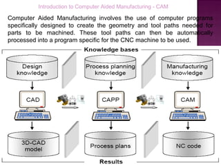
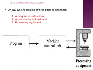
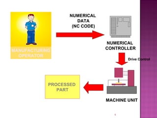
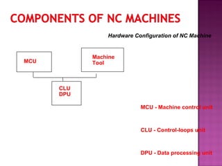
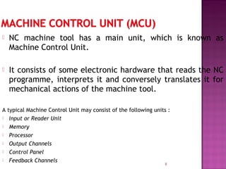
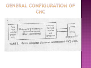
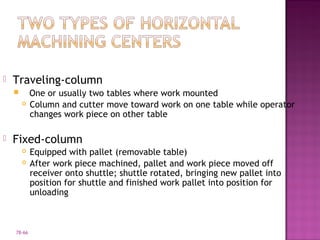
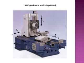
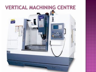
The document provides an introduction to computer aided manufacturing (CAM) and numerical control (NC) systems. It defines CAM as using computer programs to generate tool paths for machining parts. It then defines NC as a form of programmable automation where a machine's mechanical actions are controlled by a coded program. The basic components of an NC system are described as the program of instructions, machine control unit, and processing equipment. Different types of NC machines like horizontal machining centers (HMC) and vertical machining centers (VMC) are also summarized.
difference of NC and CNC ,Part programming,Methods of manual part programming,Basic CNC input data,Preparatory Functions ,Miscellaneous Functions,Interpolation:Canned cycles:part programming on component,Tool length compensation,Cutter Radius,Task compensation:Types of media of NC
Advantages & Limitations of CNC machine tools,Introduction DNC,Component of a DNC system,Principle,Functions of DNC
Types of DNC systems,Comparison between NC, CNC and DNC machine tools
Introduction to CNC machine and Hardware. aman1312
Complete detailing of cnc machine and its operations with its required hardware necessary for increasing its Automation and increasing its manufacturing capability. Also increase in complex shape manufacturing.
GT Definition,Implementing Group Technology (GT),four methods GT, 1.OPTIZ PARTS CLASSIFICATION AND CODING SYSTEM,2.MICLASS coding system ,CODE MDSI System,BENEFITS OF GROUP TECHNOLOGY and limitations.
CIM is the architecture for integrating the engineering, marketing and manufacturing functions through information technologies. In the broad
sense, CIM involves the integration of all the business processes from supplier to end consumer.
Modern Machine Tools:
CNC machines: Introduction, principles of operation,
Types – Vertical machining centres and horizontal machining centres,
major elements, functions, applications,
controllers,
open loop and closed loop systems
Types of automatic machines,
Transfer machines
Numerical Control (NC) machine tools – CNC types, constructional details, special features, machining centre, and part programming fundamentals CNC – manual part programming – micromachining – wafer machining
Student information management system project report ii.pdfKamal Acharya
Our project explains about the student management. This project mainly explains the various actions related to student details. This project shows some ease in adding, editing and deleting the student details. It also provides a less time consuming process for viewing, adding, editing and deleting the marks of the students.
Explore the innovative world of trenchless pipe repair with our comprehensive guide, "The Benefits and Techniques of Trenchless Pipe Repair." This document delves into the modern methods of repairing underground pipes without the need for extensive excavation, highlighting the numerous advantages and the latest techniques used in the industry.
Learn about the cost savings, reduced environmental impact, and minimal disruption associated with trenchless technology. Discover detailed explanations of popular techniques such as pipe bursting, cured-in-place pipe (CIPP) lining, and directional drilling. Understand how these methods can be applied to various types of infrastructure, from residential plumbing to large-scale municipal systems.
Ideal for homeowners, contractors, engineers, and anyone interested in modern plumbing solutions, this guide provides valuable insights into why trenchless pipe repair is becoming the preferred choice for pipe rehabilitation. Stay informed about the latest advancements and best practices in the field.
Sachpazis:Terzaghi Bearing Capacity Estimation in simple terms with Calculati...Dr.Costas Sachpazis
Terzaghi's soil bearing capacity theory, developed by Karl Terzaghi, is a fundamental principle in geotechnical engineering used to determine the bearing capacity of shallow foundations. This theory provides a method to calculate the ultimate bearing capacity of soil, which is the maximum load per unit area that the soil can support without undergoing shear failure. The Calculation HTML Code included.
Overview of the fundamental roles in Hydropower generation and the components involved in wider Electrical Engineering.
This paper presents the design and construction of hydroelectric dams from the hydrologist’s survey of the valley before construction, all aspects and involved disciplines, fluid dynamics, structural engineering, generation and mains frequency regulation to the very transmission of power through the network in the United Kingdom.
Author: Robbie Edward Sayers
Collaborators and co editors: Charlie Sims and Connor Healey.
(C) 2024 Robbie E. Sayers
TECHNICAL TRAINING MANUAL GENERAL FAMILIARIZATION COURSEDuvanRamosGarzon1
AIRCRAFT GENERAL
The Single Aisle is the most advanced family aircraft in service today, with fly-by-wire flight controls.
The A318, A319, A320 and A321 are twin-engine subsonic medium range aircraft.
The family offers a choice of engines
Automobile Management System Project Report.pdfKamal Acharya
The proposed project is developed to manage the automobile in the automobile dealer company. The main module in this project is login, automobile management, customer management, sales, complaints and reports. The first module is the login. The automobile showroom owner should login to the project for usage. The username and password are verified and if it is correct, next form opens. If the username and password are not correct, it shows the error message.
When a customer search for a automobile, if the automobile is available, they will be taken to a page that shows the details of the automobile including automobile name, automobile ID, quantity, price etc. “Automobile Management System” is useful for maintaining automobiles, customers effectively and hence helps for establishing good relation between customer and automobile organization. It contains various customized modules for effectively maintaining automobiles and stock information accurately and safely.
When the automobile is sold to the customer, stock will be reduced automatically. When a new purchase is made, stock will be increased automatically. While selecting automobiles for sale, the proposed software will automatically check for total number of available stock of that particular item, if the total stock of that particular item is less than 5, software will notify the user to purchase the particular item.
Also when the user tries to sale items which are not in stock, the system will prompt the user that the stock is not enough. Customers of this system can search for a automobile; can purchase a automobile easily by selecting fast. On the other hand the stock of automobiles can be maintained perfectly by the automobile shop manager overcoming the drawbacks of existing system.
COLLEGE BUS MANAGEMENT SYSTEM PROJECT REPORT.pdfKamal Acharya
The College Bus Management system is completely developed by Visual Basic .NET Version. The application is connect with most secured database language MS SQL Server. The application is develop by using best combination of front-end and back-end languages. The application is totally design like flat user interface. This flat user interface is more attractive user interface in 2017. The application is gives more important to the system functionality. The application is to manage the student’s details, driver’s details, bus details, bus route details, bus fees details and more. The application has only one unit for admin. The admin can manage the entire application. The admin can login into the application by using username and password of the admin. The application is develop for big and small colleges. It is more user friendly for non-computer person. Even they can easily learn how to manage the application within hours. The application is more secure by the admin. The system will give an effective output for the VB.Net and SQL Server given as input to the system. The compiled java program given as input to the system, after scanning the program will generate different reports. The application generates the report for users. The admin can view and download the report of the data. The application deliver the excel format reports. Because, excel formatted reports is very easy to understand the income and expense of the college bus. This application is mainly develop for windows operating system users. In 2017, 73% of people enterprises are using windows operating system. So the application will easily install for all the windows operating system users. The application-developed size is very low. The application consumes very low space in disk. Therefore, the user can allocate very minimum local disk space for this application.
Welcome to WIPAC Monthly the magazine brought to you by the LinkedIn Group Water Industry Process Automation & Control.
In this month's edition, along with this month's industry news to celebrate the 13 years since the group was created we have articles including
A case study of the used of Advanced Process Control at the Wastewater Treatment works at Lleida in Spain
A look back on an article on smart wastewater networks in order to see how the industry has measured up in the interim around the adoption of Digital Transformation in the Water Industry.
Cosmetic shop management system project report.pdfKamal Acharya
Buying new cosmetic products is difficult. It can even be scary for those who have sensitive skin and are prone to skin trouble. The information needed to alleviate this problem is on the back of each product, but it's thought to interpret those ingredient lists unless you have a background in chemistry.
Instead of buying and hoping for the best, we can use data science to help us predict which products may be good fits for us. It includes various function programs to do the above mentioned tasks.
Data file handling has been effectively used in the program.
The automated cosmetic shop management system should deal with the automation of general workflow and administration process of the shop. The main processes of the system focus on customer's request where the system is able to search the most appropriate products and deliver it to the customers. It should help the employees to quickly identify the list of cosmetic product that have reached the minimum quantity and also keep a track of expired date for each cosmetic product. It should help the employees to find the rack number in which the product is placed.It is also Faster and more efficient way.
2. Introduction to Computer Aided Manufacturing - CAM
Computer Aided Manufacturing involves the use of computer programs
specifically designed to create the geometry and tool paths needed for
parts to be machined. These tool paths can then be automatically
processed into a program specific for the CNC machine to be used.
3. A Definition:A Definition:
• Numerical Control is a system
in which actions are controlled by
the direct insertion of numerical
data at some point.
• In other words, Programmable
automation in which the
mechanical actions of a ‘machine
tool’ are controlled by a program
containing coded alphanumeric3
4. Definition of Numerical Control (NC)
• Numerical Control (NC) is a form of programmable automation in
which the mechanical actions of a machine tool or other
equipment are controlled by a program containing coded
instructions (alphanumeric data)
• The collection of all instructions (or program of instruction)
necessary to machine a part is called an NC program, CNC
program, or a part program.
• The person who prepares this program is called a part programmer.
5. Basic Components of NC System
• An NC system consists of three basic components:
1. A program of instructions,
2. A machine control unit, and
3. Processing equipment.
8. NC machine tool has a main unit, which is known as
Machine Control Unit.
It consists of some electronic hardware that reads the NC
programme, interprets it and conversely translates it for
mechanical actions of the machine tool.
A typical Machine Control Unit may consist of the following units :
Input or Reader Unit
Memory
Processor
Output Channels
Control Panel
Feedback Channels
8
9. 9
Machine Tool
•Machine tool is the main components of a numerical
control system, which executes the operations.
•It may consist of worktable, cutting tools, jigs and fixtures,
motors for driving spindle and coolant and lubricating
system.
•The latest development in the numerical control machine
tool is the versatile machining center.
•This is a single machine capable of doing a number of
operations such as milling, boring, drilling, reaming, and
tapping by Automatic Tool Changer (ATC) under the control
of tool selection instruction.
10. NC Technology
• The NC system uses a fixed logical functions, those that are built-in and
permanently wired within the control unit.
• These functions can not be changed by the programmer or the machine
tool operator.
• The system can interpret a part program, but it does not allow any
changes to the program.
• NC system requires the use of punched tapes for input of the program
instructions.
18. Advantages and Disadvantages of NC
• The advantages generally attributed to NC, with emphasis on machine tool
applications, are the following:
1. Non-productive time is reduced (fewer setups, less setup time, reduced
work piece handling time, and automatic tool changes).
2. Greater accuracy and repeatability.
3. More-complex part geometries are possible.
4. Simplified tooling and work holding.
5. Operator skill-level requirements are reduced.
6. Inspection requirements are reduced.
• The disadvantages of NC include the following:
1. Higher investment cost.
2. Higher maintenance effort.
3. Part programming.
19. Motion Control Systems for NC
• Motion control systems for NC can be divided into two types:
1. Point-to-point systems.
2. Continuous systems.
(1) Point-to-point systems (positioning systems)
• These systems move the worktable to a programmed location without regard
for the path taken to get to that location.
• Once the move has been completed, some processing action is
accomplished by the workhead at the location, such as drilling or punching a
hole.
20. Motion Control Systems for NC
(2) Continuous Path Systems
• Generally refer to systems that are capable of continuous simultaneous
control of two or more axes.
• This provides control of the tool trajectory relative to the workpart.
• The tool performs the process while the worktable is moving, thus
enabling the system to generate angular surfaces, 2D curves, and 3D
contours.
21. Types of Continuous paths
• Straight-Cut
When continuous path control is utilized to move the tool parallel to only
one of the major axes of the machine tool worktable.
• Contouring
When continuous path control is used for simultaneous control of two or
more axes in machining operations.
24. Conventional Numerical Control (NC)
Computer Numerical Control (CNC)
Direct Numerical Control (DNC)
Adaptive Control (AC)
24
25. Computer Numerical Control is a numerical
control system that utilizes a dedicated stored
programmed. Computer is used to perform
some or all basic function. Numerical control
is a programmable automation in which
process is controlled by Numbers, Letters, and
symbols. (Computer +NC= CNC).
26.
27. Part program:
A part program is a series of coded instructions
required to produce a part. It controls the
movement of the machine tool and on/off
control of auxiliary functions such as spindle
rotation and coolant. The coded instructions are
composed of letters, numbers and symbols.
Program input device:
The program input device is the means for part
program to be entered into the CNC control.
Three commonly used program input devices are
punch tape reader, magnetic tape reader, and
computer via RS-232-C communication.
28. Machine Control Unit:
The machine control unit (MCU) is the heart of a CNC system. It
is used to perform the following functions:
To read the coded instructions.
To decode the coded instructions.
To implement interpolations (linear, circular, and helical) to
generate axis motion commands.
To feed the axis motion commands to the amplifier circuits for
driving the axis mechanisms.
To receive the feedback signals of position and speed for each
drive axis.
To implement auxiliary control functions such as coolant or
spindle on/off and tool change
29. Drive System:
A drive system consists of amplifier circuits,
drive motors, and ball lead-screws. The MCU
feeds the control signals (position and speed) of
each axis to the amplifier circuits. The control
signals are augmented to actuate drive motors
which in turn rotate the ball lead-screws to
position the machine table.
Machine Tool:
CNC controls are used to control various types of
machine tools. Regardless of which type of
machine tool is controlled, it always has a slide
table and a spindle to control of position and
speed. The machine table is controlled in the X
and Y axes, while the spindle runs along the Z
axis.
30. Feed Back System:
The feedback system is also referred to as
the measuring system. It uses position and
speed transducers to continuously monitor
the position at which the cutting tool is
located at any particular instant. The MCU
uses the difference between reference
signals and feedback signals to generate the
control signals for correcting position and
speed errors.
31.
32. Machine Tool Control
In Process Compensation
Improved programming and operating features
Diagnostics
33. Machine tool control
Hybrid CNC –Hard-wired logic circuits for
functions like feed rate generation , circular
interpolation etc. in addition to computer
Mass production of circuits and less
expensive computer
Straight CNC –Computer to perform all NC
functions
34.
35.
36. In-process compensation
Dynamic correction of machine tool motion for
changes or errors that occur during processing
Adjustment of errors sensed by in-process inspection
probes and gauges
Recomputation of axis positions when an inspection
probe is used to locate a datum reference on the
work part
Offset adjustments for tool radius and length
Adaptive control adjustments to sped and feed
Computation of predicted tool life and selection of
alternate tooling when indicated.
37. Improved programming and operating
features
Use of tape and tape reader only once
On-line editing of part programs at the machine
Special canned cycles.
Graphic display of tool path to verify the tape
Various types of interpolation: circular, parabolic, cubic
Support of various units. Conversion from one unit to
another unit.
Use of specially written subroutines or macros
Manual data input (MDI)
Several part programs in bulk can be stored
38. Diagnostics
Equipped with diagnostic capability to assist in
maintaining and repairing the system
Identification of reason for downtime
Indication of imminent failure of certain
component
Redundancy of components
39. High accuracy in manufacturing
Short production time
Simpler fixturing
Contour machining (2 to 5 –axis machining)
Reduced human error
High repeatability and precision e.g. Aircraft parts
Volume of production is very high
Complex contours/surfaces need to be machined.
E.g. Turbines
Flexibility in job change, automatic tool settings,
less scrap
More safe, higher productivity, better quality
Less paper work, faster prototype production,
reduction in lead times
41. DNC is a manufacturing system in which a
number of machines are controlled by a
computer through direct- connection and in
real time.
DNC is a system connecting a set of NC
machines to a common memory for part
program or machine program storage with
provision for on- demand distribution of
data to machines.
42. Central computer
Bulk memory which stores the NC part programs
Telecommunication lines
Machine Tools.
43.
44. A central computer connected to a number of
machine tools and control them
Part program of all machine tools are stored in the
memory of the central computer and transmitted on
direct transmission lines on demand
Two way information flow take place in real time
Various machine tools can communicate with the
computer in real time
Programs in full or segment can be transferred to NC
machines
Computer can be used for program editing
No tape readers are used
No limitation for the number or size of programs
stored
45. The configuration of the DNC system can be
divided into:
1.DNC system without satellite computer.
2.DNC system with satellite computer.
Satellite computers are minicomputers and
they serve to take some of the burden off
central computer. Each satellites controls
several machine tools.
46.
47.
48. There are two alternative system configurations
by which the communication link is established
between the control computer and the machine
tool.
Behind the Tape Reader (BTR) system.
Special Machine Control Unit.
49. The computer is linked directly to the regular NC
controller unit.
Except for the source of the command instructions,
the operation of the system is very similar to
conventional NC.
The controller unit uses two temporary storage
buffers to receive blocks of instructions from the
DNC computer and convert them into machine
actions.
One buffer is receiving a block of data, the other is
providing control instructions to machine tool.
Cost is very less
50. Replace the regular controller unit with a special
machine control unit.
The special control unit is designed to facilitate
communication between the machine tool and
the computer.
The special MCU configuration achieve a superior
balance between accuracy of the interpolation
and fast metal removal rates than is generally
possible with the BTR system
51. Behind the Tape Reader (BTR)
system Special Machine Control Unit
52. The functions which a DNC system is
designed to perform:
NC without punched tape.
NC part program storage.
Data collection, processing, and reporting.
Communication
53. The program storage subsystem must be structured
to satisfy several purposes:
The program must be made available for
downloading to the NC machine tools.
The subsystem must allow for new programs to be
entered, old programs to be deleted, and existing
programs to be edited.
The storage subsystem must be structured to
perform certain data processing and management
functions, such as file security, displays of
programs, and manipulation of data
54. The purpose of this functions is to "monitor"
production of the factory.
The data concerned are:
Tool usage
Machine utilization
Production piece counts
These data must be processed by the DNC
computer, and reports are prepared to provide
management with information necessary for
running the plant.
55. Communication Network" is required to
accomplish the previous functions of DNC.
The essential communication links in DNC are
between the following components of the
system:
Central computer and machine tools
Central computer and NC part programmer
terminal
Central computer and bulk memory
56. Elimination of punched tapes and tape
readers
Convenient storage of NC part programs in
computer files
Greater computational capability and
flexibility
Reporting of shop performance.
Convenient editing and diagnostic features
57. DNC concepts represents a first step in the
development of production plants which will
be managed by computer systems. This
establishes the framework for the evolution
of computer automated factories
58. “to adapt” means to change a behavior to conform
to new circumstances.
An adaptive controller
a controller that can modify its behavior in
response to the changes in dynamics of the
processes and the disturbances acting on the
process.
A self-correcting form of optimal control
59. In machining, it includes automatic adjustment of cutting
parameters like speeds, feeds, depth of cut, etc.
60. Adaptive controller performs 3 functions
1. Identification
- Identifies the current value of performance index
- Functions continuously to be dynamic
1. Decision
- decide what changes have to be made to improve
system performance
3. Modification
- implement the decision
61. Increased production rate
Increased tool life
Greater part protection
Increases machine life
Less operator intervention
Easier part programming
62.
63. Industrial surveys in 1960's showed smaller
machine components requiring several operations
tool long time to complete
Part sent to several machines before finished
There was much "operator intervention" during
machining process
In late 1960s and early 70s, begin to design
machine that would perform several operations
and do 90% of machining on one machine
64. CNC machine centre is advance manufacturing
machine tool which performs wide range of
machining operation with accuracy and
inspection free product with good quality
surface finishing.
Operations done on drilling, milling and lathe
can be performed on CNC machine centre.
A computer-controlled machine tool capable of
many types of cutting operations on multiple
surfaces and directions on a work piece
66. 78-66
Traveling-column
One or usually two tables where work mounted
Column and cutter move toward work on one table while operator
changes work piece on other table
Fixed-column
Equipped with pallet (removable table)
After work piece machined, pallet and work piece moved off
receiver onto shuttle; shuttle rotated, bringing new pallet into
position for shuttle and finished work pallet into position for
unloading
68. 78-68
Saddle-type construction with sliding bedways that
use a sliding vertical head instead of quill
movement
Generally used to machine flat parts held in vise or
simple fixture
Versatility increased by addition of rotary
accessories
69.
70. These are similar to horizontal machining centers but
with the spindle axis capable of tilting from
horizontal to the vertical position continuously under
computer control.
This machine centers consists of 5 or more axis.
Such machines facilities access to the top surface of
work piece mounted on a horizontal machining centre
so that all the five sides of a components can be
machined in a single set up.
Has additional accessories such as indexible pallets
and rotary-tilt tables
71. Spindle axis can be
tilted from
horizontal to
vertical
Equivalent to 5-
axis machining
72.
73. 77-73
In mid-1960, 40% all metal-cutting operations
performed on lathes
Not very efficient
Research led to development of numerically
controlled turning centers and chucking lathes
Could produce round work almost any contour
automatically and efficiently
74. 77-74
1. CNC chucking center
• Holds part in some form of jaw chuck
• Some have dual spindles (work both ends)
1. CNC universal turning center
• Can use continuous bar feed system to machine and
cut off parts from bar
• Some have dual tool turrets
1. Combination turning/milling center
• Uses combination of turning tools
75. 77-75
Designed to machine work held in chuck
Variety of sizes from 8 to 36 in. in diameter
Four-axis chucking center has two turrets
Separate sides; each machine work at same time
Seven-tool upper turret
Seven-tool lower turret
Two-axis model has one or two turrets
Will drive only one turret at a time
76. CNC machining centers are usually designed with
features to reduce non productive time.
Automatic tool changer :- The tools are
contained in a storage unit that is integrated
with the machine tool. When a cutter needs to
be changed, the tool drum rotates to the proper
position and an automatic tool changer (ATC)
operating under program control, exchanges the
tool in the spindle for the tool in the tool storage
unit. Capacities of tool storage unit commonly
range from 16 to 80 cutting tools. •
77. Automatic work part positioner:-
Many horizontal and vertical machining
centers have the capability to orient the
work part relative to the spindle. This is
accomplished by means of a rotary table on
which work part is fixtured. The table can be
oriented at any angle about a vertical axis to
permit the cutting tool to access almost the
entire surface of the part in a single setup.
78. Machining centers are often equipped with two
(or more) separate pallets that can be
presented to the cutting tool using an automatic
pallet changer.
While machining is performed with one pallet in
position at the machine, the other pallet is in a
safe location away from the spindle. In this
location, the operator can unload the finished
part and then fixture the raw work part for next
cycle.
79.
80.
81. The part program is a sequence of
instructions, which describe the work, which
has to be done on a part, in the form
required by a computer under the control of
a numerical control computer program.
It is the task of preparing a program sheet
from a drawing sheet.
82. All data is fed into the numerical control
system using a standardized format.
Programming is where all the machining data
are compiled and where the data are
translated into a language which can be
understood by the control system of the
machine tool.
83. (a) Machining sequence classification of
process, tool start up point, cutting depth,
tool path, etc.
(b) Cutting conditions, spindle speed, feed
rate, coolant, etc.
(c) Selection of cutting tools.
84. Determine the startup procedure, which includes
the extraction of dimensional data from part
drawings.
Select the tool and determine the tool offset.
Set up the zero position for the work piece.
Select the speed and rotation of the spindle.
Set up the tool motions according to the profile
required.
Return the cutting tool to the reference point after
completion of work.
End the program by stopping the spindle and
coolant.
85. (a) Manual part programming,
(b) Computer aided part programming
86. The programmer first prepares the program
manuscript in a standard format.
Manuscripts are typed with a device known as flexo
writer, which is also used to type the program
instructions.
After the program is typed, the punched tape is
prepared on the flexo writer.
Complex shaped components require tedious
calculations.
This type of programming is carried out for simple
machining parts produced on point-to-point machine
tool.
87. (a) Knowledge about various manufacturing
processes and machines.
(b) Sequence of operations to be performed
for a given component.
(c) Knowledge of the selection of cutting
parameters.
(d) Editing the part program according to the
design changes.
(e) Knowledge about the codes and functions
used in part programs.
88. If five complete words are not included in each block, the
machine control unit (MCU) will not recognize the
information; therefore the control unit will not be
activated
89. The most common codes used when
programming NC machines tools are G-codes
(preparatory functions), and M codes
(miscellaneous functions).
Other codes such as F, S, D, and T are used
for machine functions such as feed, speed,
cutter diameter offset, tool number, etc.
G-codes are sometimes called cycle codes
because they refer to some action occurring
on the X, Y, and/or Z-axis of a machine tool.
90. G00 Rapid positioning
G01 Linear interpolation
G02 Circular interpolation
clockwise (CW)
G03 Circular interpolation
counterclockwise (CCW)
G20 Inch input (in.)
G21 Metric input (mm)
G24 Radius programming
G28 Return to reference point
G29 Return from reference
point
G32 Thread cutting
G40 Cutter compensation
cancel
G41 Cutter compensation left
G42 Cutter compensation right
G43 Tool length compensation
positive (+) direction
G44 Tool length compensation
minus (-) direction
G49 Tool length compensation
cancels
G 53 Zero offset or M/c
reference
G54 Settable zero offset
G84 canned turn cycle
G90 Absolute programming
G91 Incremental programming
91. M00 Program stop
M02 End of program
M03 Spindle start (forward
CW)
M04 Spindle start (reverse
CCW)
M05 Spindle stop
M06 Tool change
M08 Coolant on
M09 Coolant off
M10 Chuck - clamping
M11 Chuck - unclamping
M12 Tailstock spindle out
M13 Tailstock spindle in
M17 Tool post rotation
normal
M18 Tool post rotation
reverse
M30 End of tape and
rewind or main program
end
M98 Transfer to
subprogram
M99 End of subprogram
92. % – Main Programme (1
to 9999)
L – Sub program (1 to
999)/Home position
N – Sequence of block
number.
Lf – Block end (EOB)
means “; or *”
T – Tool number or Tool
station number
D – Tool offset
S – Spindle speed
F – Feed
M – Switching function
G – Transverse
commands
R – Parameters
I, J, K – Circle
parameters
B/U/R – Radius
X/Y/Z – Axis
coordinates
P – Passes
93. If the complex-shaped component requires
calculations to produce the component are done
by the programming software contained in the
computer.
The programmer communicates with this system
through the system language, which is based on
words.
94. There are various programming languages
developed in the recent past, such as
APT (Automatically Programmed Tools),
ADAPT, AUTOSPOT, COMPAT-II, 2CL, ROMANCE,
SPLIT is used for writing a computer programme,
which has English like statements.
A translator known as compiler program is used to
translate it in a form acceptable to MCU
95. The APT language was the product of MIT development work
on NC programming systems.
Its development began in June 1956, and it was first used in
production around 1959.
Today it is the most widely used language in NC part
programming.
Although first intended as a contouring language , modern
versions of APT can be used for both positioning and
continuous path programming.
96. The four types of statements in the APT language are:
1. Geometry Statements: which define primitive elements such as points,
lines, circles, planes, cones and spheres. They are also sometimes called
definition statements
2. Motion Statements: which describe the tool path in relation to the part
geometry
3. Postprocessor Statements: which give specific machine tool code
information as well as feeds and speeds
4. Auxiliary Statements: which give part and tool tolerances
97. The general form of geometry statements is:
symbol = geometry type / descriptive data
An example of such statement is:
P1 = POINT/100.0, 200.0, 300.0
The statement is made up of three sections.
The first is the symbol use to identify the geometric element. Normally the
alphabet “P” is used for defining a Point, “C” for Circle, “L” for Line and
“Pl” for Plane.
The second section of the geometry statement is an APT vocabulary word
that identifies the type of geometry element. e.g. POINT, LINE, CIRCLE,
PLANE, etc.
The third section of the geometry statement is the descriptive data
100. P3 = POINT / XSMALL, INTOF, L1, C1
Or P3 = POINT / YSMALL, INTOF, L1, C1
P4 = POINT / XLARGE, INTOF, L1, C1
Or P4 = POINT / YLARGE, INTOF, L1, C1
P3
C1
L1
P4
Y
X
101. P3 = POINT / XSMALL, INTOF,C1,C2
Or P3 = POINT / YLARGE, INTOF, C1,C2
P4 = POINT / XLARGE, INTOF, C1,C2
Or P4 = POINT / YSMALL, INTOF, C1,C2
P3
P4
C1
C2
Y
X
110. APT motion statements have a general format:
motion command / descriptive data
e.g. GOTO / P1
At the beginning of the motion statements tool must be given a starting
point
FROM / P0
Or FROM / -2, -2, 0
The FROM is an APT vocabulary word which indicates that this is the
initial point from which others will be referenced. The FROM statement
occurs only once at the start of the motion sequence.
In APT there are two basic types of motion statements:
a) Point to Point motion
b) Contouring motion
111. There are only two basic point to point motion commands
GOTO:
The GOTO statement instructs the tool to go to a particular point location
specified in the descriptive data.
e.g. GOTO / P2
GOTO / 2, 7, 0
GODLTA:
The GODLTA command specifies an incremental move for the tool.
e,g, GODLTA / 2, 7, 0 instructs the tool to move from its
present position to 2 units in x-direction, 7 units in y-direction and 0 units
in z-direction
112. Modifier words, such as TO, ON, PAST or TANTO, are used to govern the
position of the tool in relation to the check surface.
113. Motion statements, GOLFT (go to the left), GOFWD (go forward) and
GORGT(go to the right), are also used to control the cutter motion.
114. 3. POST PROCESSOR STATEMENT
Post processor command for a particular tool are :
MACHIN/ : use to specify the machine tool and call the post processor for the tool.
e.g.- MACHIN/DRILL,3
COOLNT/ : allow the coolant fluid to be turned on or off.
e.g.- COOLNT/OFF
COOLNT /ON
COOLNT/FLOOD
COOLNT/MIST
FEDRAT/: specifies the feed rate for moving the tool along the part surface in
inches per minutes:
e.g.- FEDRAT/4.5
SPINDL/: gives the spindle rotation speed in revolution per minute.
e.g.- SPINDL/ 850
FINI: end of program
115. 4. AUXILIARY STATEMENTS
• It give part and tool tolerances.
• The statement used for this are
INTOL/0.0015
OUTTOL/0.001