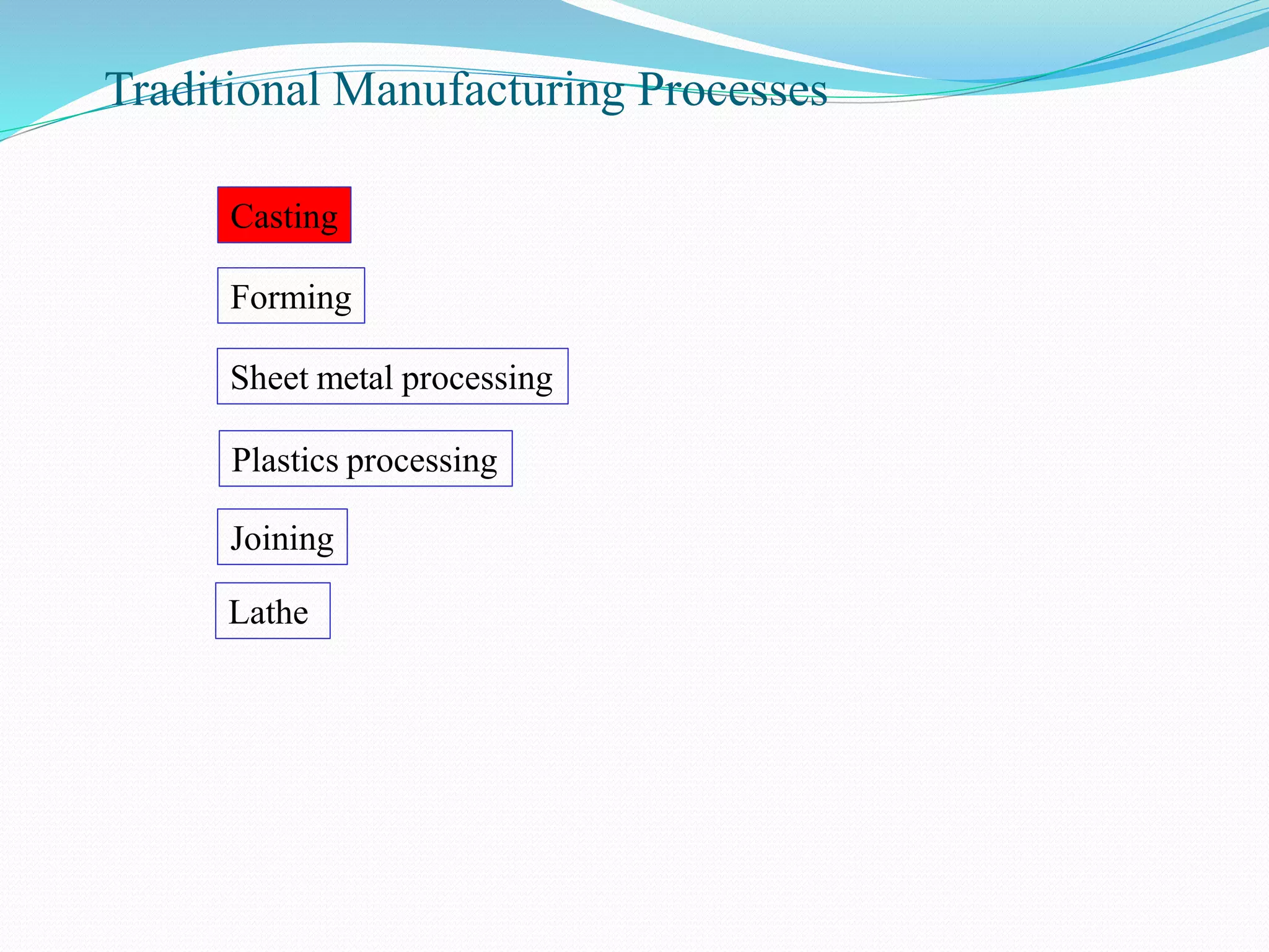
This document discusses various manufacturing processes and provides details about casting processes. It describes:
1) Casting as one of the earliest metal shaping techniques known to humans involving pouring molten metal into a refractory mold and allowing it to solidify.
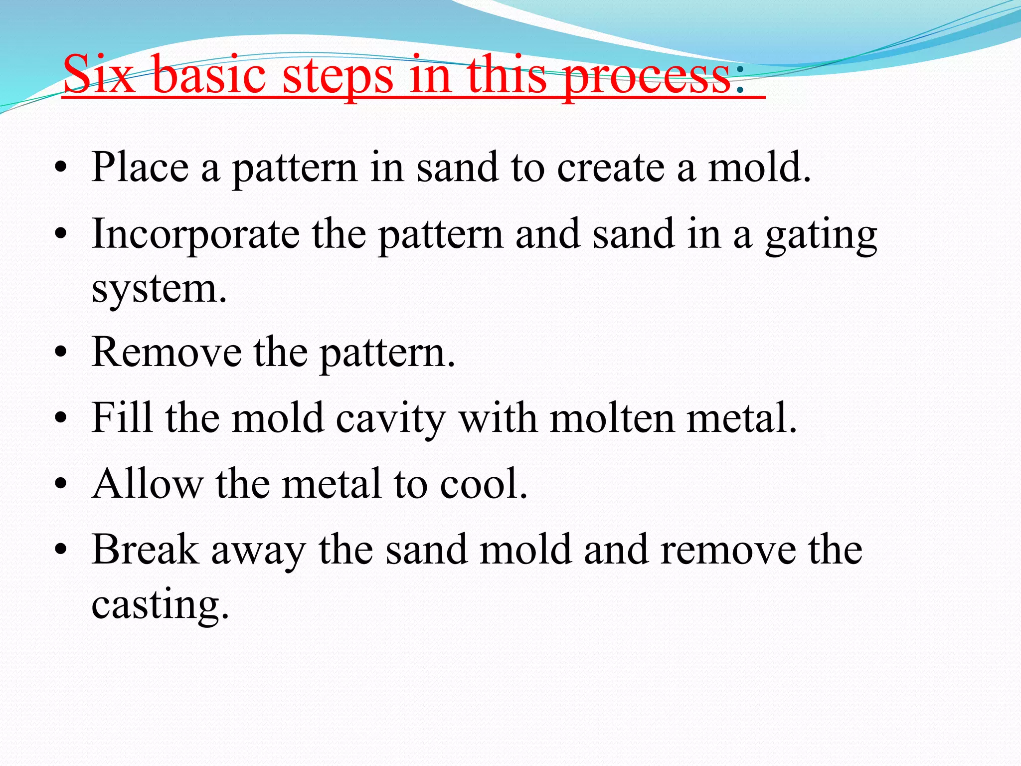
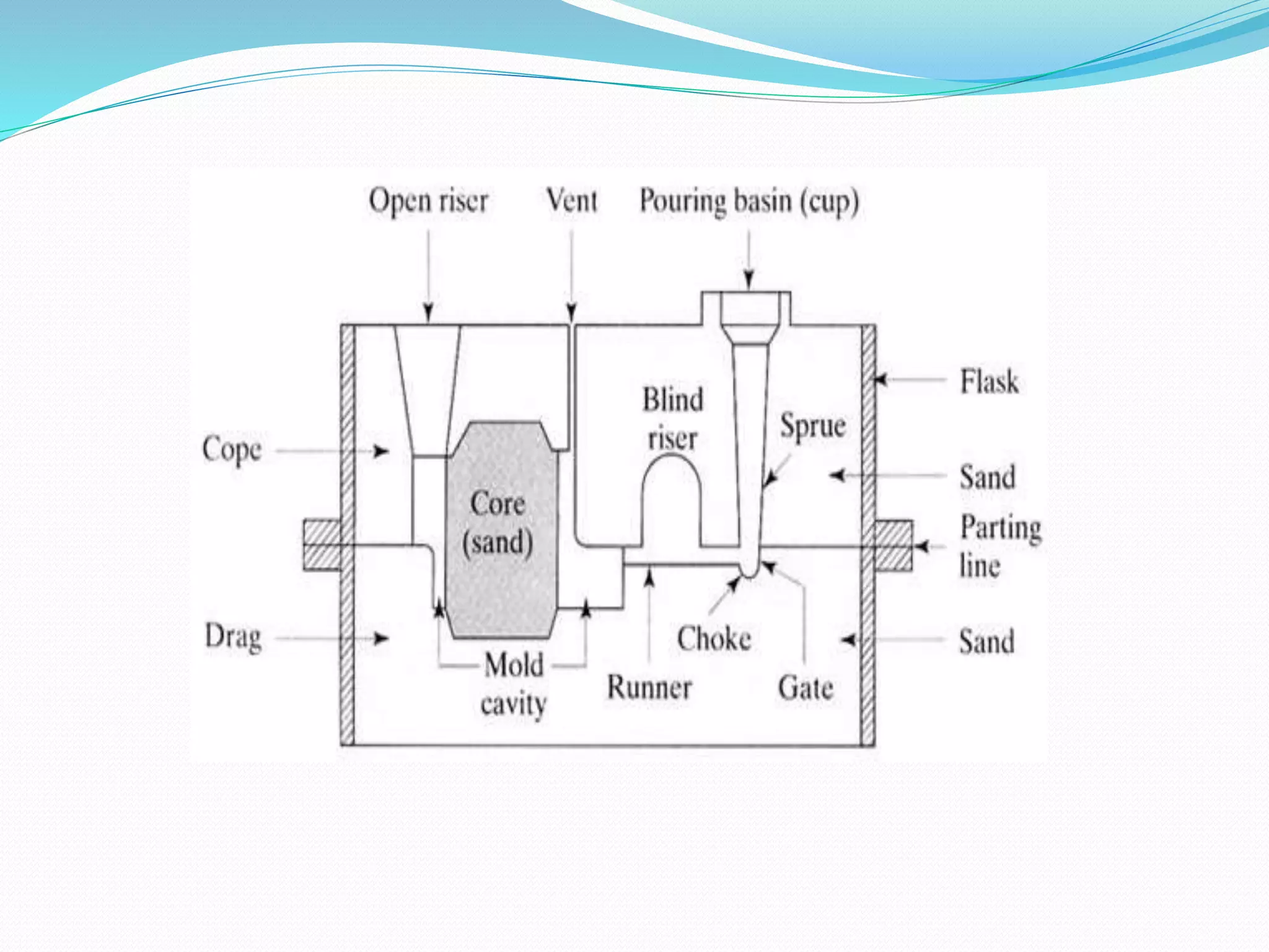
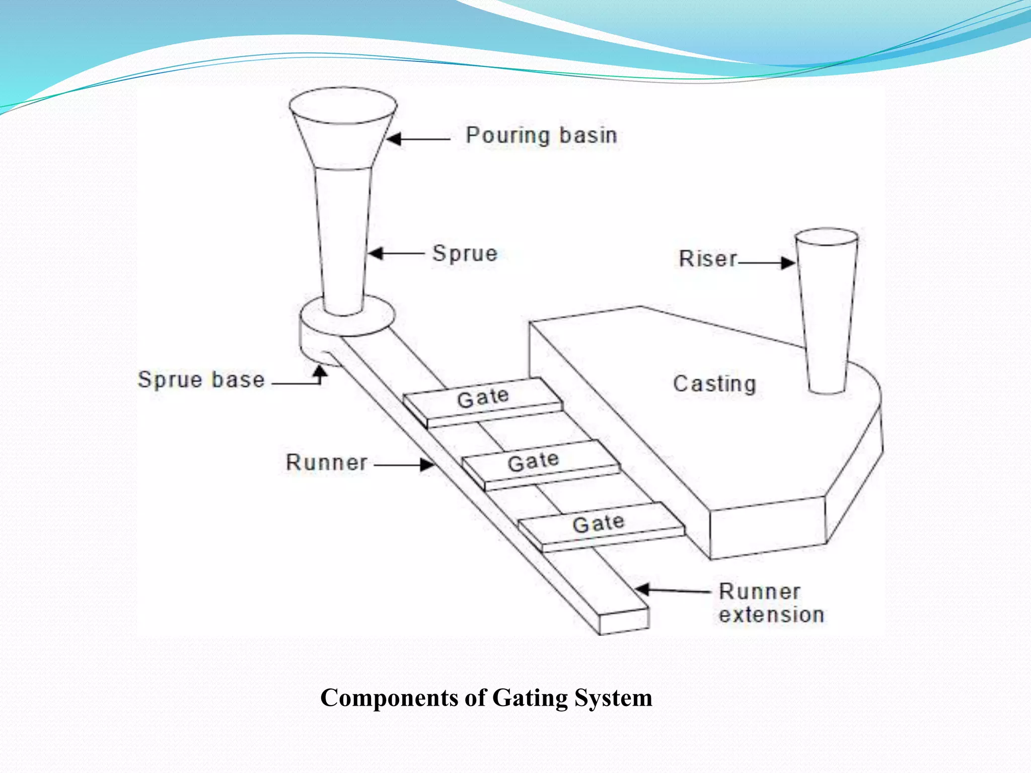
2) The six basic steps in the casting process including creating a mold cavity, incorporating gating systems, filling with molten metal, and allowing the metal to cool.
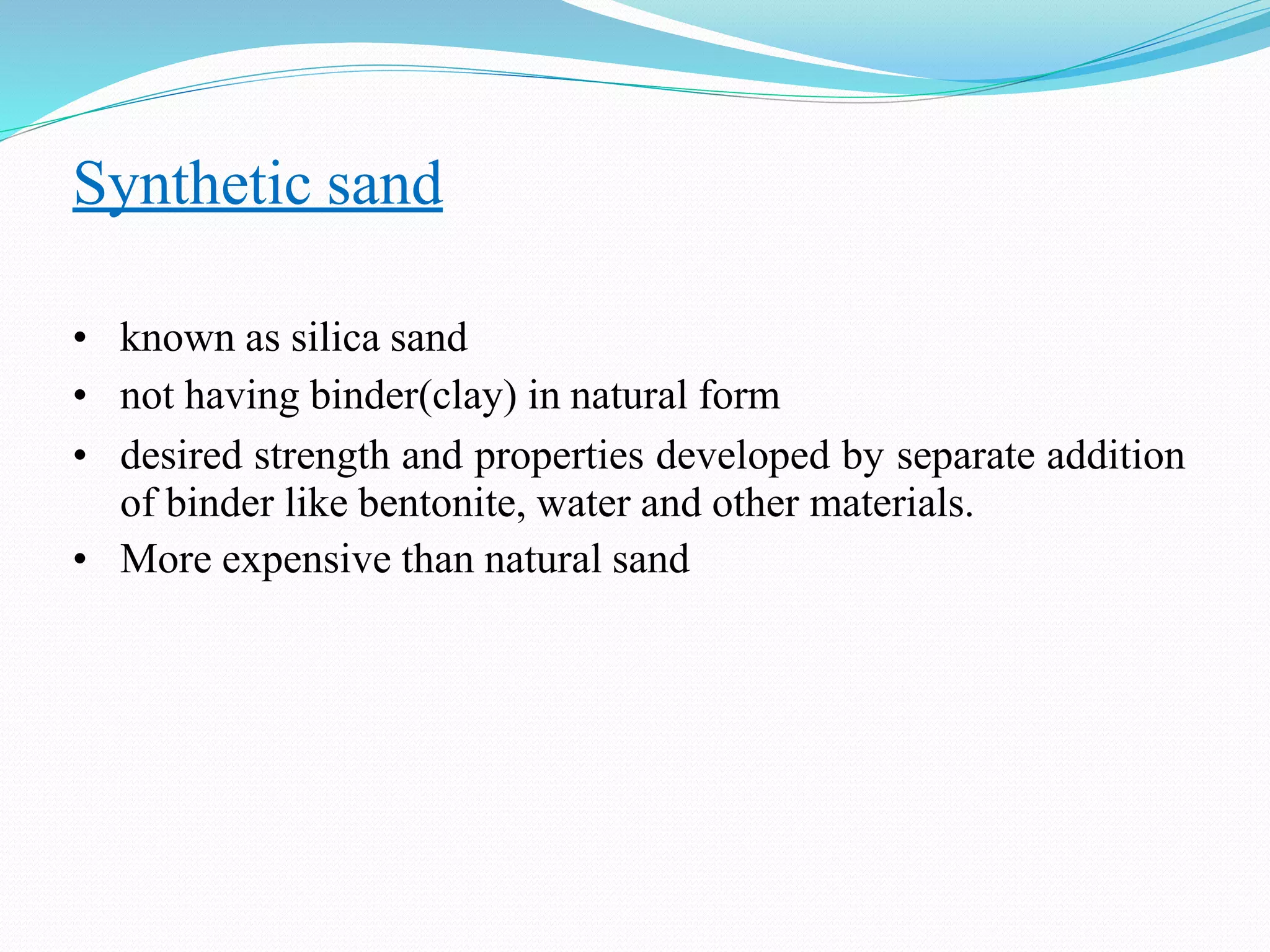
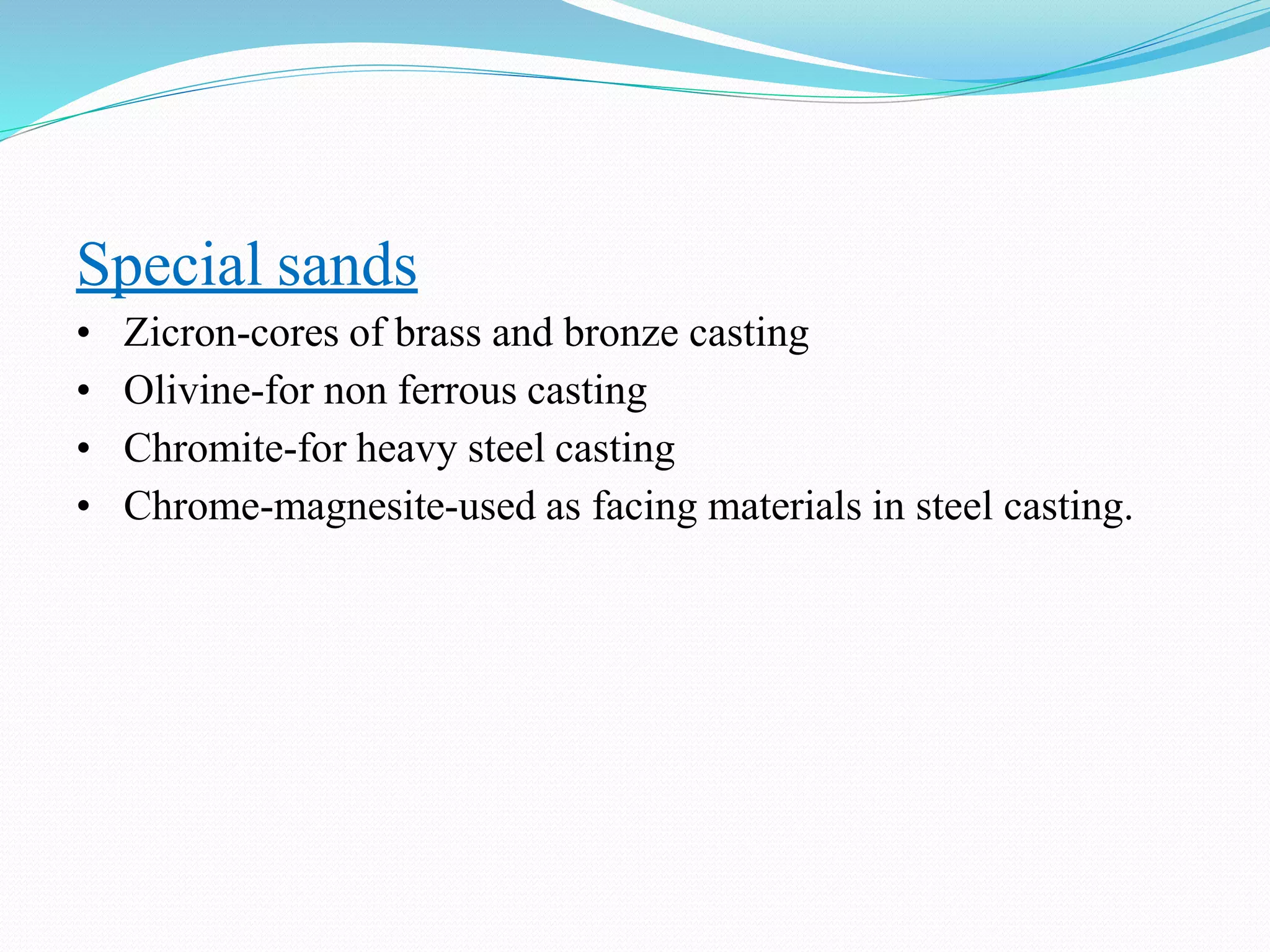
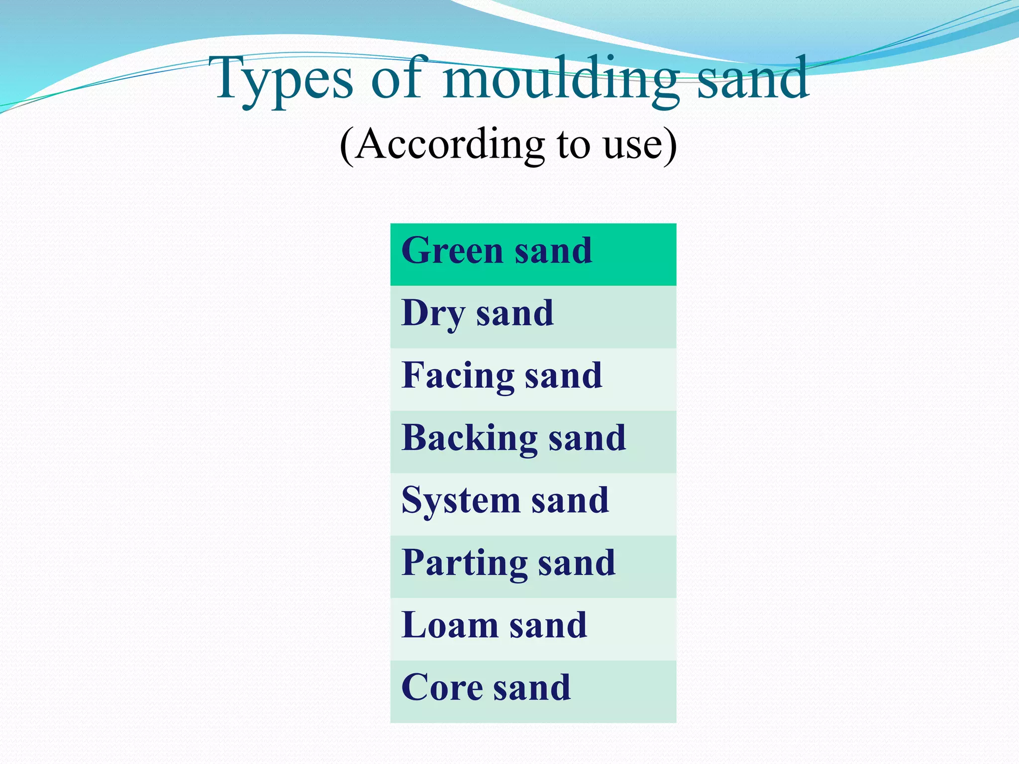
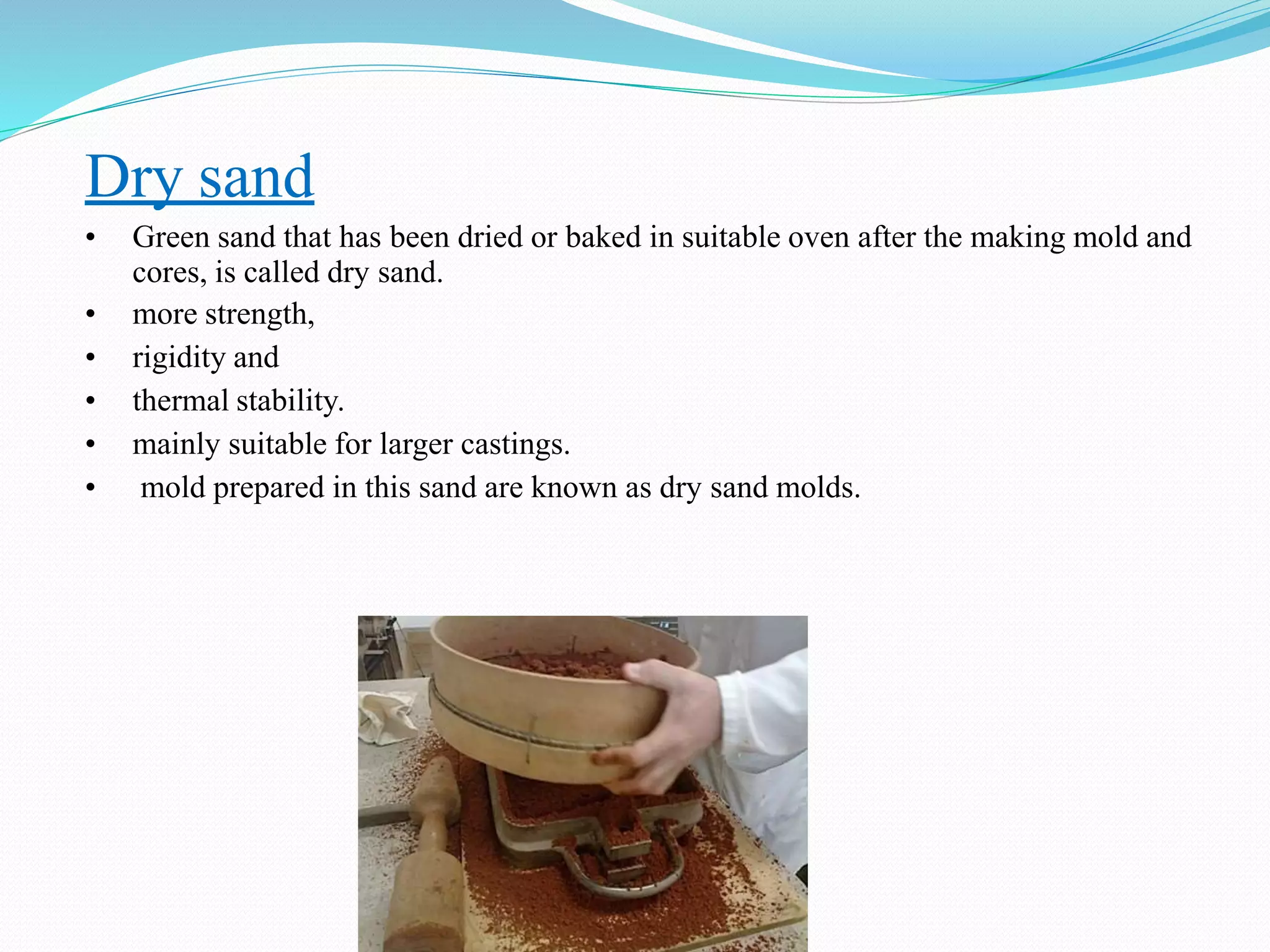
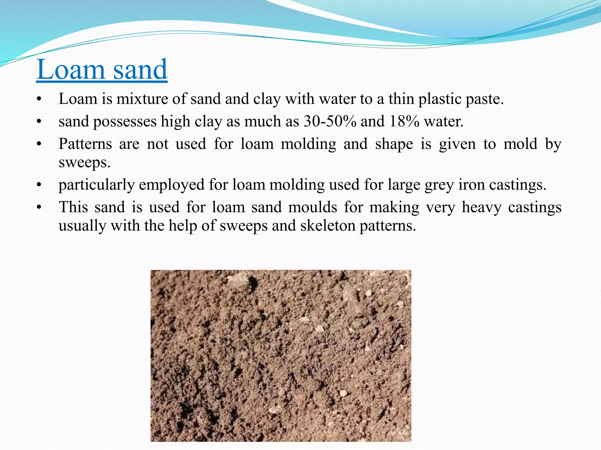
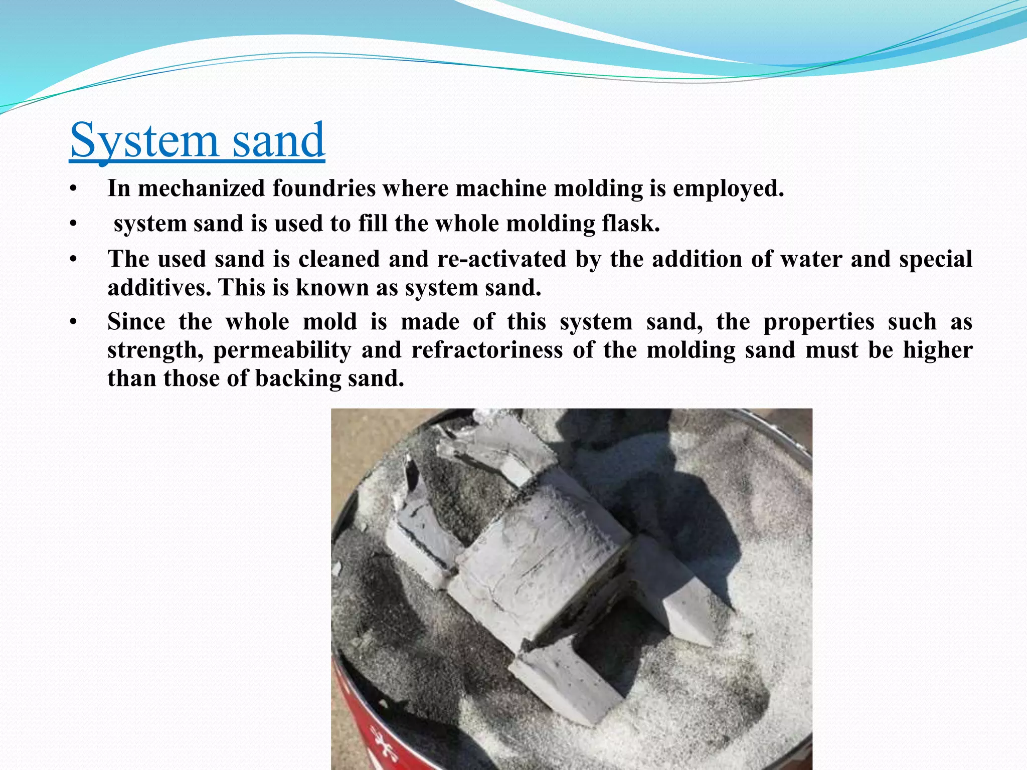
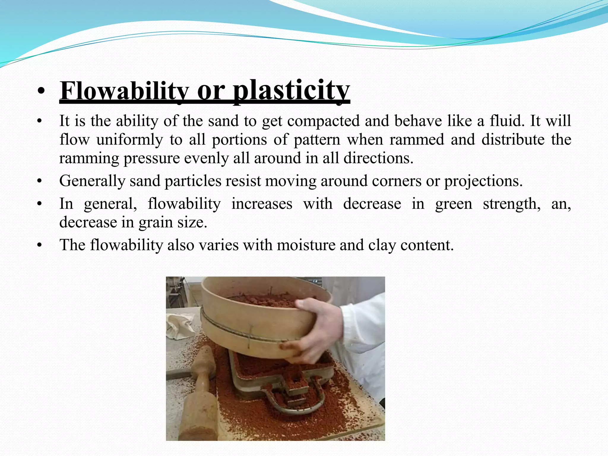
3) Common molding sand types used in casting like green sand, dry sand, and loam sand.