Downloaded 846 times

![Rapid prototyping/Additive manufacturing
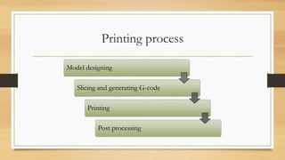
• Layered manufacturing
• Part is produced by producing multiple “slices”
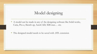
• From 3D model [STL file] to physical object
Additive manufacturing
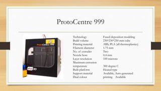
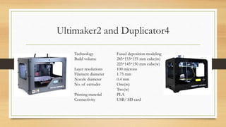
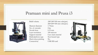
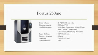
Fused deposition modeling
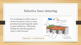
Selective laser sintering
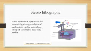
Stereo lithography](https://image.slidesharecdn.com/fdmppt-170423070139/85/FUSED-DEPOSITION-MODELING-2-320.jpg)
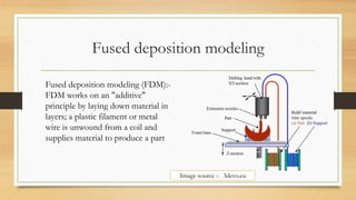
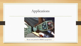


The document discusses Fused Deposition Modeling (FDM) as a method used in additive manufacturing, which constructs objects layer by layer from a 3D model. It outlines various printing technologies, materials used, potential defects, and applications in industries such as aerospace and healthcare. Challenges mentioned include print quality, affordability, and the need for repeatability in producing functional parts.


