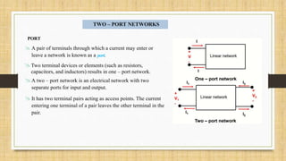
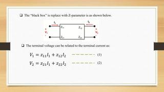
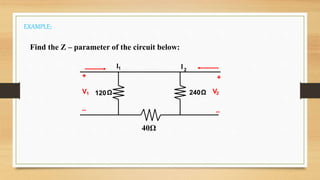
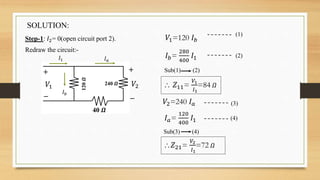
 Name : Shubhajit Chatterjee, Arendra Singh
 Student Code : BWU/BEC/19/028,BWU/BEC/19/027.
 Course Name :Network Theory
 Course code :PCC-EC304.
 Program : Bachelor of Technology in Electronics & Communication Engineering.
 Semester : 3rd Semester.
TWO – PORT NETWORKS
PORT
 A pair of terminals through which a current may enter or
leave a network is known as a port.
A two – port network is an electrical network with two
separate ports for input and output.
It has two terminal pairs acting as access points. The current
entering one terminal of a pair leaves the other terminal in the
pair.
Two terminal devices or elements (such as resistors,
capacitors, and inductors) results in one – port network.
Why we study two port – network:
 Such networks are useful in communication, control system, power systems
and electronics.
 Knowing the parameters of a two – port network enables us to treat it as a
“Black box” when embedded within a larger network.
From the network, we can observe that there are 4 variables that is I1, I2, V1and V2
which two are independent.
The various term that relate these voltages and currents are called Parameters.
Z – PARAMETER
 Z – parameter also called as impedance parameter
and the units is ohm (Ω)
 Impedance parameters is commonly used in the synthesis of
filters and also useful in the design and analysis of
impedance matching networks and power distribution
networks.
 The two – port network may be voltage – driven or current –
driven.
 The “black box” is replace with Z-parameter is as shown below.
 The terminal voltage can be related to the terminal current as:
𝑉1 = 𝑧11 𝐼1 + 𝑧12 𝐼2
𝑉2 = 𝑧21 𝐼1 + 𝑧22 𝐼2
(1)
(2)
In matrix form as:
𝑉1
𝑉2
=
𝑧11 𝑧12
𝑧21 𝑧22
𝐼1
𝐼2
The Z-parameter that we want to
determine are 𝑧11, 𝑧12, 𝑧21, 𝑧22.
The value of the parameters can be
evaluated by setting:
1. 𝐼1 = 0 (input port open – circuited)
2. 𝐼2= 0 (output port open – circuited)
𝑧11=
𝑉1
𝐼1
𝑧12=
𝑉1
𝐼2
𝑧21=
𝑉2
𝐼1
𝑧22=
𝑉2
𝐼2
𝐼1 = 0
𝐼1 = 0𝐼2 = 0
𝐼2 = 0
Where;
𝑧11= open – circuit input impedance .
𝑧12= open – circuit transfer impedance from port 1 to port 2.
𝑧21= open – circuit transfer impedance from port 2 to port 1.
𝑧22= open – circuit output impedance.
240Ω120Ω
+
V1
_
+
V2
_
I1 I 2
40Ω
Find the Z – parameter of the circuit below:
EXAMPLE:
SOLUTION:
Step-1: 𝐼2= 0(open circuit port 2).
Redraw the circuit:-
𝐼1 𝐼 𝑎
+
_
𝑉2𝑉1
+
_
40 𝜴
240 𝜴120𝜴
𝐼 𝑏
𝑉1=120 𝐼 𝑏
𝐼 𝑏=
280
400
𝐼1
Sub(1) (2)
 𝑍11=
𝑉1
𝐼1
=84 𝛺
(2)
(1)
𝑉2=240 𝐼 𝑎
𝐼 𝑎=
120
400
𝐼1
Sub(3) (4)
𝑍21=
𝑉2
𝐼1
=72 𝛺
(4)
(3)
Step-2: 𝐼1= 0 (open circuit port 1).
Redraw the circuit.
𝑰 𝒙
𝑰 𝟐
𝑰 𝒚
240 𝜴120 𝜴
40 𝜴
+ +
-_
𝑉1 𝑉2
𝑉2=240 𝐼 𝑥
𝐼 𝑥=
160
400
𝐼2
Sub(1) (2)
 𝑍22=
𝑉2
𝐼2
=96 𝛺
(1)
(2)
𝑉1=120 𝐼 𝑦
𝐼 𝑦=
240
400
𝐼2
Sub(4) (3)
 𝑍12=
𝑉1
𝐼2
=72 𝛺
(3)
(4)In matrix form:
𝑍 =
84 72
72 96
Z parameters

Z parameters

  • 1.
     Name :Shubhajit Chatterjee, Arendra Singh  Student Code : BWU/BEC/19/028,BWU/BEC/19/027.  Course Name :Network Theory  Course code :PCC-EC304.  Program : Bachelor of Technology in Electronics & Communication Engineering.  Semester : 3rd Semester.
  • 2.
    TWO – PORTNETWORKS PORT  A pair of terminals through which a current may enter or leave a network is known as a port. A two – port network is an electrical network with two separate ports for input and output. It has two terminal pairs acting as access points. The current entering one terminal of a pair leaves the other terminal in the pair. Two terminal devices or elements (such as resistors, capacitors, and inductors) results in one – port network.
  • 3.
    Why we studytwo port – network:  Such networks are useful in communication, control system, power systems and electronics.  Knowing the parameters of a two – port network enables us to treat it as a “Black box” when embedded within a larger network. From the network, we can observe that there are 4 variables that is I1, I2, V1and V2 which two are independent. The various term that relate these voltages and currents are called Parameters.
  • 4.
    Z – PARAMETER Z – parameter also called as impedance parameter and the units is ohm (Ω)  Impedance parameters is commonly used in the synthesis of filters and also useful in the design and analysis of impedance matching networks and power distribution networks.  The two – port network may be voltage – driven or current – driven.
  • 6.
     The “blackbox” is replace with Z-parameter is as shown below.  The terminal voltage can be related to the terminal current as: 𝑉1 = 𝑧11 𝐼1 + 𝑧12 𝐼2 𝑉2 = 𝑧21 𝐼1 + 𝑧22 𝐼2 (1) (2)
  • 7.
    In matrix formas: 𝑉1 𝑉2 = 𝑧11 𝑧12 𝑧21 𝑧22 𝐼1 𝐼2 The Z-parameter that we want to determine are 𝑧11, 𝑧12, 𝑧21, 𝑧22. The value of the parameters can be evaluated by setting: 1. 𝐼1 = 0 (input port open – circuited) 2. 𝐼2= 0 (output port open – circuited) 𝑧11= 𝑉1 𝐼1 𝑧12= 𝑉1 𝐼2 𝑧21= 𝑉2 𝐼1 𝑧22= 𝑉2 𝐼2 𝐼1 = 0 𝐼1 = 0𝐼2 = 0 𝐼2 = 0 Where; 𝑧11= open – circuit input impedance . 𝑧12= open – circuit transfer impedance from port 1 to port 2. 𝑧21= open – circuit transfer impedance from port 2 to port 1. 𝑧22= open – circuit output impedance.
  • 8.
    240Ω120Ω + V1 _ + V2 _ I1 I 2 40Ω Findthe Z – parameter of the circuit below: EXAMPLE:
  • 9.
    SOLUTION: Step-1: 𝐼2= 0(opencircuit port 2). Redraw the circuit:- 𝐼1 𝐼 𝑎 + _ 𝑉2𝑉1 + _ 40 𝜴 240 𝜴120𝜴 𝐼 𝑏 𝑉1=120 𝐼 𝑏 𝐼 𝑏= 280 400 𝐼1 Sub(1) (2)  𝑍11= 𝑉1 𝐼1 =84 𝛺 (2) (1) 𝑉2=240 𝐼 𝑎 𝐼 𝑎= 120 400 𝐼1 Sub(3) (4) 𝑍21= 𝑉2 𝐼1 =72 𝛺 (4) (3)
  • 10.
    Step-2: 𝐼1= 0(open circuit port 1). Redraw the circuit. 𝑰 𝒙 𝑰 𝟐 𝑰 𝒚 240 𝜴120 𝜴 40 𝜴 + + -_ 𝑉1 𝑉2 𝑉2=240 𝐼 𝑥 𝐼 𝑥= 160 400 𝐼2 Sub(1) (2)  𝑍22= 𝑉2 𝐼2 =96 𝛺 (1) (2) 𝑉1=120 𝐼 𝑦 𝐼 𝑦= 240 400 𝐼2 Sub(4) (3)  𝑍12= 𝑉1 𝐼2 =72 𝛺 (3) (4)In matrix form: 𝑍 = 84 72 72 96