Download to read offline
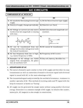


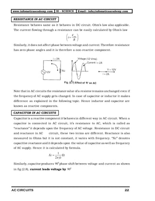
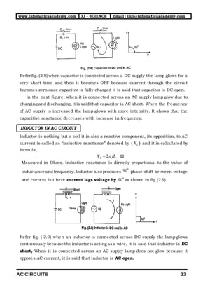

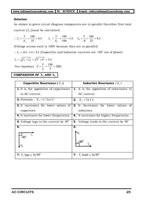


The document compares alternating current (AC) and direct current (DC) systems, detailing their characteristics, advantages, and behaviors in circuits. It explains concepts like frequency, amplitude, reactance, and impedance in relation to AC circuits, and presents formulas for calculating various electrical values. The document also discusses resonance in electrical circuits, specifically in radio and TV applications, emphasizing the significance of resonant frequency.


