
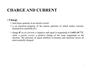
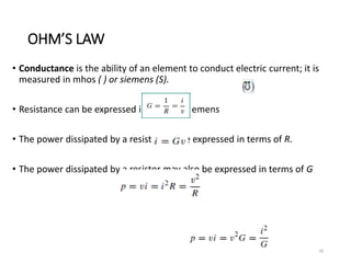
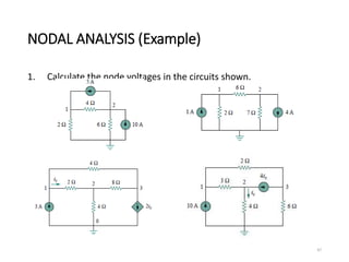


The document provides an extensive overview of electrical circuit analysis, covering key concepts such as charge, current, voltage, power, energy, circuit elements, and laws governing circuits. It discusses foundational principles like Ohm's Law, Kirchhoff’s Laws, and methodologies like nodal and mesh analysis for system evaluation. Additionally, it introduces dependent and independent sources, and techniques for analyzing complex circuits like series and parallel configurations.


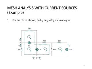
![Lecture 1a [compatibility mode]](https://cdn.slidesharecdn.com/ss_thumbnails/lecture1acompatibilitymode-130523045820-phpapp02-thumbnail.jpg?width=640&height=640&fit=bounds)