This document provides an overview of fundamental electrical engineering concepts including:
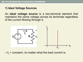
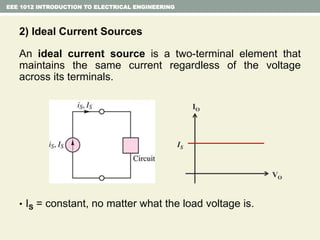
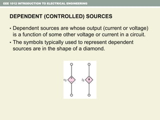
- Independent and dependent voltage/current sources and ideal sources that maintain constant voltage/current.
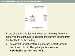
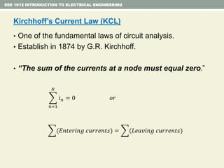
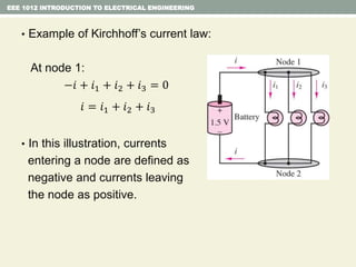
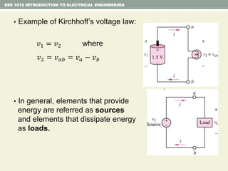
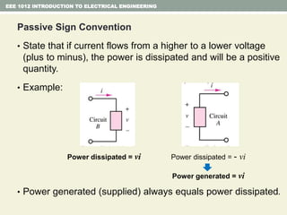
- Kirchhoff's laws for circuits - KVL states the net voltage around any closed loop is zero and KCL states the algebraic sum of currents at any node is zero.
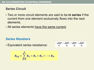
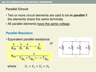
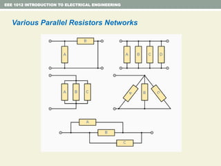
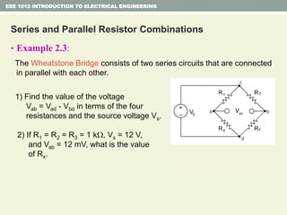
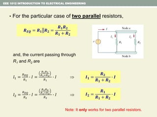
- Series and parallel resistor circuits and how to calculate equivalent resistance and current/voltage in each component.
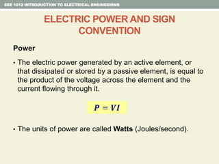
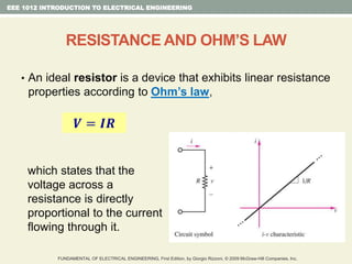
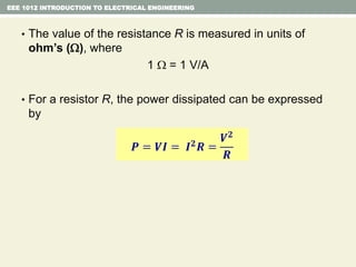
- Ohm's law relating voltage, current, and resistance and the power formula.
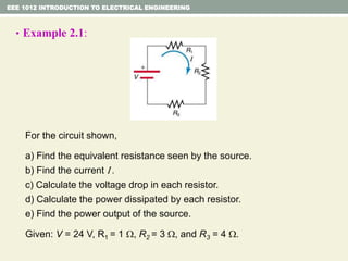
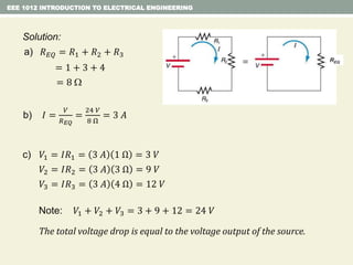
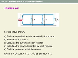
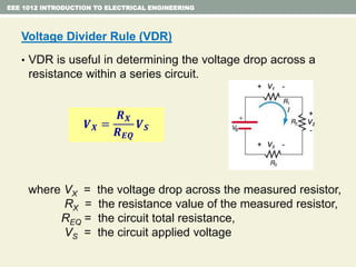
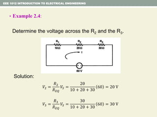
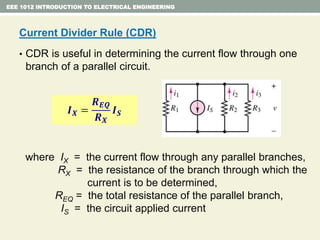
- Examples are provided to demonstrate applying concepts like nodal analysis, mesh analysis, and voltage divider rule to solve for values in circuits.


![Lecture 1a [compatibility mode]](https://cdn.slidesharecdn.com/ss_thumbnails/lecture1acompatibilitymode-130523045820-phpapp02-thumbnail.jpg?width=640&height=640&fit=bounds)


