Downloaded 777 times

![Two Wattmeter Method to Measure 3-phase Power
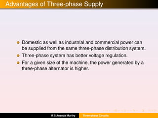
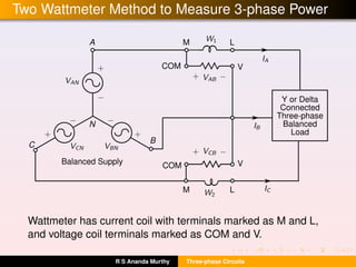
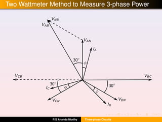
The reading of wattmeter W1 is given by
P1 = |VAB|×|IA|×cos(φ +30◦
) = |V||I|cos(30◦
+φ) (1)
where |V| and |I| are the line voltage and current respectively.
The reading of wattmeter W2 is
P2 = |VCB|×|IC|×cos(30◦
−φ) = |V||I|cos(30◦
−φ) (2)
So, the sum of the two wattmeter readings is
P1 +P2 = |V|·|I|·[cos(30◦
+φ)+cos(30◦
−φ)]
= 2|V|·|I|·cos30◦
cosφ
=
√
3|V|·|I|·cosφ (3)
which is nothing but the total three-phase active power.
R S Ananda Murthy Three-phase Circuits](https://image.slidesharecdn.com/three-phase-circuits-160430042313/85/Three-phase-circuits-17-320.jpg)
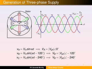
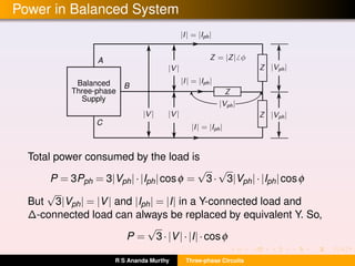
![Finding Power Factor from Two Wattmeter Readings
We can also write
P1 −P2 = |V|·|I|·[cos(30◦
+φ)−cos(30◦
−φ)]
= −2|V|·|I|·sin30◦
sinφ
= −|V|·|I|·sinφ (4)
Dividing Eq.(4) by Eq. (3) we get
P1 −P2
P1 +P2
=
−tanφ
√
3
=⇒ φ = tan−1
√
3(P2 −P1)
P1 +P2
(5)
from this the load power factor cosφ of the load can be found.
But the above equation can be applied only to balanced load.
R S Ananda Murthy Three-phase Circuits](https://image.slidesharecdn.com/three-phase-circuits-160430042313/85/Three-phase-circuits-18-320.jpg)


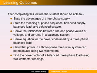
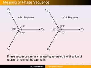
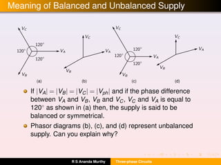
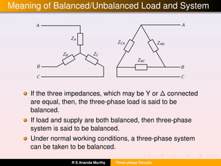
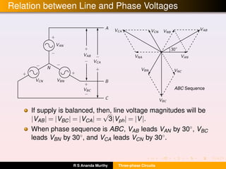
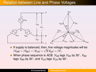
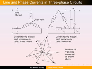
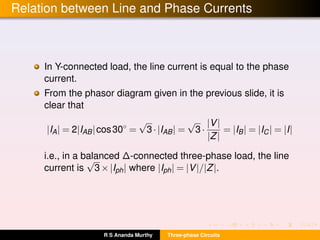
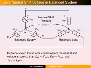
The document discusses three-phase circuits and provides information on: - The advantages of three-phase supply systems such as higher efficiency of power transfer and smoother load characteristics. - Key concepts like phase sequence, balanced/unbalanced supply and load, and the relationships between line and phase voltages and currents. - How to calculate power in a balanced three-phase system and use two wattmeters to measure total power and power factor.