Downloaded 173 times

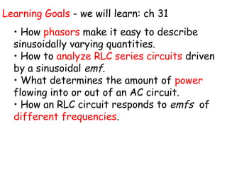
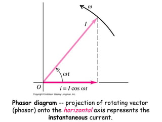
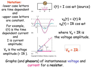

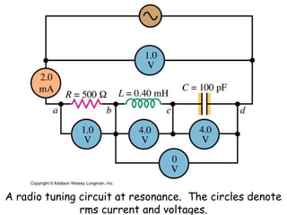
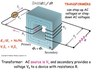
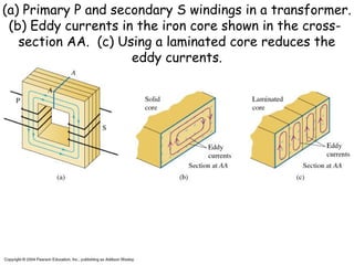
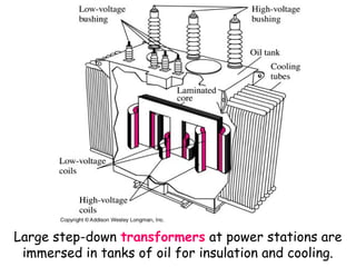


The document provides an overview of key topics in alternating current (AC) circuits covered in Chapter 31, including: 1) The use of phasors to describe sinusoidally varying quantities in AC circuits such as resistors, inductors, and capacitors. 2) Analyzing RLC series circuits driven by a sinusoidal voltage source using phasors. 3) Factors that determine the power in an AC circuit such as the current and voltage amplitudes and their phase relationship. 4) Resonance in RLC circuits and the effect of frequency on current. 5) Transformers and how they can change AC voltages and currents through electromagnetic induction.


