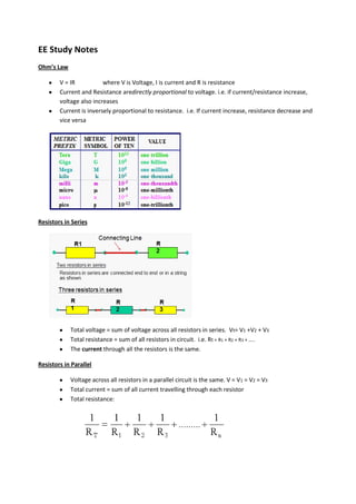
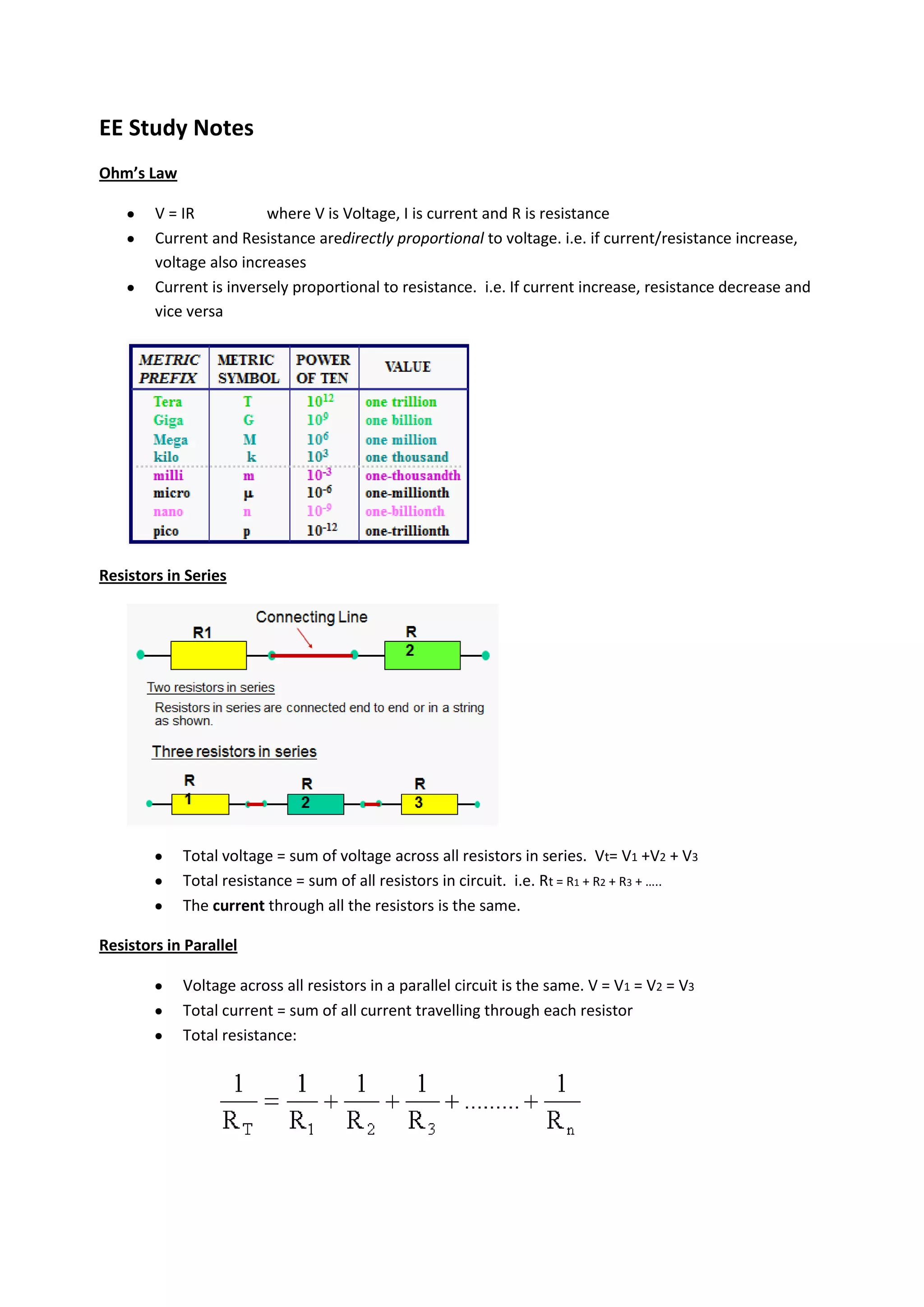
EE Study Notes
Ohmโ€™s Law

        V = IR           where V is Voltage, I is current and R is resistance
        Current and Resistance aredirectly proportional to voltage. i.e. if current/resistance increase,
        voltage also increases
        Current is inversely proportional to resistance. i.e. If current increase, resistance decrease and
        vice versa


Resistors in Series


            Total voltage = sum of voltage across all resistors in series. Vt= V1 +V2 + V3
            Total resistance = sum of all resistors in circuit. i.e. Rt = R1 + R2 + R3 + โ€ฆ..
            The current through all the resistors is the same.

Resistors in Parallel

            Voltage across all resistors in a parallel circuit is the same. V = V1 = V2 = V3
            Total current = sum of all current travelling through each resistor
            Total resistance:
Power, Energy & Efficiency

         Unit of Charge: Coulomb (Q)
         Unit of Energy : Joules (J) or kWh (kilowatt-hours)
         Unit of Power : Watts or J/s (W)
                          Energy = I2Rt joules
                                   = Power x Time
         Power = Voltage x Current                P=IV
         The totalpower for both seriesand parallel circuits, is equal to the sum of the powers in each
         resistor :

                                 PT = P1 + P2 + P3 + โ€ฆ โ€ฆ + Pn

         Efficiency:


Cells
         Types of cells
            o Wet Leclanche Cell
            o Dry Leclanche Cell
            o Mercury Cell
            o Carbon-Zinc Dry Cell
            o Alkaline-Manganese Cell

Internal Resistance

V = E โ€“ Ir
V = IR

where V = terminal voltage of cell
         E = open circuit voltage of cell
         r = internal resistance of cell
         R = load resistance
          I = load current
The emf (E) of a cell is the total voltage generated by the
                                          cell is measured with the cell open-circuit (also called open circuit
                                          voltage of cell).


                                                     The terminal voltage, or potential difference (p.d.) of a
                                           cell, is the voltage across the cell terminals when the cell is
                                           supplying current to a load


Capacitors

       A capacitor is a device which stores energy in the form of electric charge.
       Symbol : C,      Unit: Farad (F)
       Capacitance = Charge / Voltage


       The larger the capacitance, the larger will be the charge stored.
       Capacitance (C) is directly proportional to the dielectric permittivity( ).


   Capacitors in Parallel & Series

             In series:              1      1     1     1
                                     CT     C1    C2    C3
In Parallel:         CT = C1 + C2 + C3 + ... ...+ Cn

AC Circuits


    Period - The time required for a given sine wave to complete one full cycle.
        o symbol - T
        o unit - second (s)

    Period Measurement - From one zero crossing to the corresponding zero crossing in the next
    cycle

    Frequency - The number of cycles a sine wave can complete in 1 second.

        o symbol : f
        o unit - Hertz (Hz)
    Frequency vs Period


    If an ac voltage is applied to a circuit, an ac current flows.The voltage and current will have
    the same frequency.
    Ways to express and measure the value of a sine wave :
         o instantaneous value.
         o peak value.
         o peak-to-peak value.
         o root-mean-square value.
         o average value.
Peak Value - The voltage or current value of a waveform at its maximum positive or negative
          points.

             o   Vpor Vmax

             o   Ip or Imax

          Peak-to-Peak: The voltage or current value of a waveform measured from its minimum to its
          maximum points.

             o   Vpp or Ipp

             o   Vpp = 2 x Vmax or Vmax = 0.5 x Vpp

          Root Mean Square Value
             o Vrms= 0.707 x Vmax

          Average Value
             o Vavg= 0.637 x Vmax

Phasor Diagram

      There are three ways to describe the phase angle in a phasor diagram:

             1. Same phase or in phase

             2. Leading

             3. Lagging

      Characteristics of A.C. Pure Resistive Circuit
         o Voltage and current are equally opposed by the circuit.
         o The current(I) flows through the resistor is in-phase with the applied voltage(V).
         o The phase angle between the applied voltage and current is 0ยฐ

                                         V
                                         I = ----
                                               R


      Characteristics of A.C. Pure Inductive Circuit
         o There is opposition to current flow.
         o Current flows through the pure inductor lags the applied voltage by 90ยฐ.
         o The phase angle between the applied voltage and current is 90ยฐ. ( = 90ยฐ )

                                         XL = 2 f L

                    XL: inductive reactance( ), f: Frequency(Hz), L: Inductance(H)
Characteristics of A.C. Pure Capacitive Circuit
         o Current flows through the pure capacitor leads the applied voltage by 90ยฐ.
         o The phase angle between the applied voltage and current is 90ยฐ. ( = 90ยฐ )

                                           1
                                           Xc = ---------
                                                2 fC


                   Xc: Capacitive reactance( ), f: Frequency(Hz), C: Capacitance(F)

Impedence

      Characteristics of A.C. RL Series Circuit
         o Current is in phase with VR.
         o Current lags VL by 90o.
         o Current lags VS by where is the phase angle or phase difference.

      Impedence: The opposition to the current flow is called the impedance.
         o Symbol : Z
         o Unit     : Ohms ( )

      Formulae:
         o Vs = IZ            where Vs = supply voltage, I = current, and Z = impedence


            o                    where Z = impedence, R = Resistance, and XL= inductive reactance

      Characteristics of A.C. RC Series Circuit
         o Current is in phase with VR.
         o Current leads VC by 90o.
         o Current leads VS by where is the phase angle or phase difference.
      Formulae:
         o Vs = IZ             where Vs = supply voltage, I = current, and Z = impedence


            o                   where Z = impedence, R = Resistance, and Xc= capacitive reactance
Ee study notes

Ee study notes

  • 1.
    EE Study Notes Ohmโ€™sLaw V = IR where V is Voltage, I is current and R is resistance Current and Resistance aredirectly proportional to voltage. i.e. if current/resistance increase, voltage also increases Current is inversely proportional to resistance. i.e. If current increase, resistance decrease and vice versa Resistors in Series Total voltage = sum of voltage across all resistors in series. Vt= V1 +V2 + V3 Total resistance = sum of all resistors in circuit. i.e. Rt = R1 + R2 + R3 + โ€ฆ.. The current through all the resistors is the same. Resistors in Parallel Voltage across all resistors in a parallel circuit is the same. V = V1 = V2 = V3 Total current = sum of all current travelling through each resistor Total resistance:
  • 2.
    Power, Energy &Efficiency Unit of Charge: Coulomb (Q) Unit of Energy : Joules (J) or kWh (kilowatt-hours) Unit of Power : Watts or J/s (W) Energy = I2Rt joules = Power x Time Power = Voltage x Current P=IV The totalpower for both seriesand parallel circuits, is equal to the sum of the powers in each resistor : PT = P1 + P2 + P3 + โ€ฆ โ€ฆ + Pn Efficiency: Cells Types of cells o Wet Leclanche Cell o Dry Leclanche Cell o Mercury Cell o Carbon-Zinc Dry Cell o Alkaline-Manganese Cell Internal Resistance V = E โ€“ Ir V = IR where V = terminal voltage of cell E = open circuit voltage of cell r = internal resistance of cell R = load resistance I = load current
  • 3.
    The emf (E)of a cell is the total voltage generated by the cell is measured with the cell open-circuit (also called open circuit voltage of cell). The terminal voltage, or potential difference (p.d.) of a cell, is the voltage across the cell terminals when the cell is supplying current to a load Capacitors A capacitor is a device which stores energy in the form of electric charge. Symbol : C, Unit: Farad (F) Capacitance = Charge / Voltage The larger the capacitance, the larger will be the charge stored. Capacitance (C) is directly proportional to the dielectric permittivity( ). Capacitors in Parallel & Series In series: 1 1 1 1 CT C1 C2 C3
  • 4.
    In Parallel: CT = C1 + C2 + C3 + ... ...+ Cn AC Circuits Period - The time required for a given sine wave to complete one full cycle. o symbol - T o unit - second (s) Period Measurement - From one zero crossing to the corresponding zero crossing in the next cycle Frequency - The number of cycles a sine wave can complete in 1 second. o symbol : f o unit - Hertz (Hz) Frequency vs Period If an ac voltage is applied to a circuit, an ac current flows.The voltage and current will have the same frequency. Ways to express and measure the value of a sine wave : o instantaneous value. o peak value. o peak-to-peak value. o root-mean-square value. o average value.
  • 5.
    Peak Value -The voltage or current value of a waveform at its maximum positive or negative points. o Vpor Vmax o Ip or Imax Peak-to-Peak: The voltage or current value of a waveform measured from its minimum to its maximum points. o Vpp or Ipp o Vpp = 2 x Vmax or Vmax = 0.5 x Vpp Root Mean Square Value o Vrms= 0.707 x Vmax Average Value o Vavg= 0.637 x Vmax Phasor Diagram There are three ways to describe the phase angle in a phasor diagram: 1. Same phase or in phase 2. Leading 3. Lagging Characteristics of A.C. Pure Resistive Circuit o Voltage and current are equally opposed by the circuit. o The current(I) flows through the resistor is in-phase with the applied voltage(V). o The phase angle between the applied voltage and current is 0ยฐ V I = ---- R Characteristics of A.C. Pure Inductive Circuit o There is opposition to current flow. o Current flows through the pure inductor lags the applied voltage by 90ยฐ. o The phase angle between the applied voltage and current is 90ยฐ. ( = 90ยฐ ) XL = 2 f L XL: inductive reactance( ), f: Frequency(Hz), L: Inductance(H)
  • 6.
    Characteristics of A.C.Pure Capacitive Circuit o Current flows through the pure capacitor leads the applied voltage by 90ยฐ. o The phase angle between the applied voltage and current is 90ยฐ. ( = 90ยฐ ) 1 Xc = --------- 2 fC Xc: Capacitive reactance( ), f: Frequency(Hz), C: Capacitance(F) Impedence Characteristics of A.C. RL Series Circuit o Current is in phase with VR. o Current lags VL by 90o. o Current lags VS by where is the phase angle or phase difference. Impedence: The opposition to the current flow is called the impedance. o Symbol : Z o Unit : Ohms ( ) Formulae: o Vs = IZ where Vs = supply voltage, I = current, and Z = impedence o where Z = impedence, R = Resistance, and XL= inductive reactance Characteristics of A.C. RC Series Circuit o Current is in phase with VR. o Current leads VC by 90o. o Current leads VS by where is the phase angle or phase difference. Formulae: o Vs = IZ where Vs = supply voltage, I = current, and Z = impedence o where Z = impedence, R = Resistance, and Xc= capacitive reactance