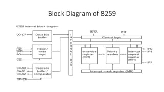
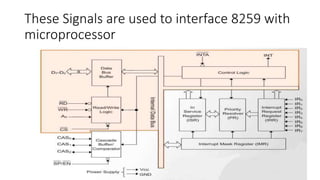
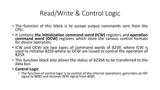
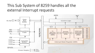
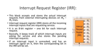
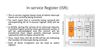
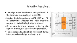
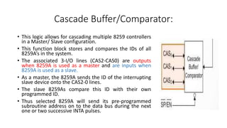
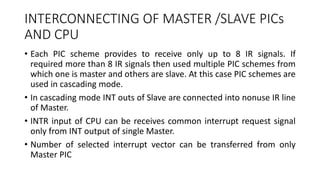
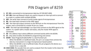
SlideShare a Scribd company logo
INTEL 8259A Programmable
Interrupt Controller
8259 PIC
• The 8259A is a programmable interrupt controller(PIC) specially designed
to work with Intel microprocessor 8080, 8085A, 8086, 8088.
• It is a tool for managing the interrupt requests and functions as an overall
manager in an Interrupt-Driven system environment.
• It accepts requests from the peripheral equipment, determines which of
the incoming requests is of the highest priority, ascertains whether the
incoming request has a higher priority value than the level currently being
serviced, and issues an interrupt to the CPU based on this determination.
• The PIC, after issuing an Interrupt to the CPU, must somehow input
information into the CPU that can ``point'' the Program Counter to the
service routine associated with the requesting device.
8259 PIC
• 8259 PIC can handle up to 8 vectored priorities interrupts for the
processor and it can be cascaded in master-slave configuration to
handle 64 levels of interrupts without any additional circuitry.
• It can be programmed either in level triggered or in edge triggered
interrupt level and also we can masked individual bits of interrupt
request register.
• It has Internal priority resolver which can be programmed into fixed
priority mode and rotating priority mode.
Block Diagram of 8259
These Signals are used to interface 8259 with
microprocessor
Data bus buffer:
• This, bidirectional 8-bit buffer is used to interface the 8259A to the
system data bus.
• Control words and status information from the microprocessor to PIC
and from PIC to microprocessor respectively, are transferred through
the data bus buffer.
• The processor sends control word to data bus buffer through D0-D7.
• The processor read status word from data bus buffer through D0-D7
• Also, after selection of Interrupt by 8259 microprocessor, it transfer
the opcode of the selected Interrupt and address of the Interrupt
service sub routine to the other connected microprocessor.
Read/Write & Control Logic
• The function of this block is to accept output commands sent from the
CPU.
• It contains the initialization command word (ICW) registers and operation
command word (OCW) registers which store the various control formats
for device operation.
• ICW and OCW are two types of command words of 8259, where ICW is
used to initialize 8259 where as OCW are issued to control the operation of
8259.
• This function block also allows the status of 8259A to be transferred to the
data bus.
• Control Logic
• The function of control logic is to control all the internal operations, generates an INT
signal to 8085 and receives INTA signal from 8085.
Pins Connected with Read/Write & Control
Logic
• RD, WR, CS and A0 are the control signals used in Read/Write
and Control Logic.
• The processor uses the RD (low), WR (low) and A0 to read or
write 8259.
• A LOW on WR input enables the CPU to write control words
(ICWs and OCWs) to the 8259A.
• A LOW on RD input enables the 8259A to send the status of
the Interrupt Request Register (IRR), In Service Register (ISR),
the Interrupt Mask Register (IMR), or the Interrupt level onto
the Data Bus.
• A0 input signal is used in conjunction with WR and RD signals
to write commands into the various command registers, as well
as reading the various status registers of the chip. This line can
be tied directly to one of the address lines
This Sub System of 8259 handles all the
external Interrupt requests
Interrupt Request Register (IRR):
• This block accepts and stores the actual interrupt
requests from external interrupting devices on IR0 –
IR7 lines.
• Interrupt request register (IRR) stores all the incoming
interrupt inputs that are requesting service.
• It is an 8-bit register – one bit for each interrupt
request.
• Basically, it keeps track of which interrupt inputs are
asking for service and also stores the pending
interrupt requests.
• If an interrupt input is unmasked, and has an
interrupt signal on it, then the corresponding bit in
the IRR will be set.
Interrupt Mask Register (IMR):
• This logic block masks interrupt lines based on
programming by the processo and prevents
masked interrupt lines from interrupting the
processor.
• The IMR is used to disable (Mask) or enable
(Unmask) individual interrupt request inputs.
• This is also an 8-bit register. Each bit in this
register corresponds to the interrupt input with
the same number.
• The IMR operates on the IRR. Masking of higher
priority input will not affect the interrupt request
lines of lower priority.
• To unmask any interrupt the corresponding bit is
set ‘0’
In-service Register (ISR):
• The in-service register keeps track of which interrupt
inputs are currently being serviced.
• For each input that is currently being serviced the
corresponding bit of in-service register (ISR) will be
set.
• In 8259A, during the service of an interrupt request,
if another higher priority interrupt becomes active, it
will be acknowledged and the control will be
transferred from lower priority interrupt service
subroutine (ISS) to higher priority ISS.
• Thus, more than one bit of ISR will be set indicating
the number of interrupts being serviced.
• Each of these 3-registers can be read as status
register.
Priority Resolver:
• This logic block determines the priorities of
the incoming interrupts set in the IRR.
• It takes the information from IRR, IMR and ISR
to determine whether the new interrupt
request is having highest priority or not.
• If the new interrupt request is having the
highest priority, it is selected and processed.
• The corresponding bit of ISR will be set during
interrupt acknowledge machine cycle
Cascade Buffer/Comparator:
• This logic allows for cascading multiple 8259 controllers
in a Master/ Slave configuration.
• This function block stores and compares the IDs of all
8259A’s in the system.
• The associated 3-I/O lines (CAS2-CAS0) are outputs
when 8259A is used as a master and are inputs when
8259A is used as a slave.
• As a master, the 8259A sends the ID of the interrupting
slave device onto the CAS2-0 lines.
• The slave 8259As compare this ID with their own
programmed ID.
• Thus selected 8259A will send its pre-programmed
subroutine address on to the data bus during the next
one or two successive INTA pulses.
How does the Master-Slave concept work?
• The slave 8259 creates an interrupt trigger on master as soon as it
receives an interrupt trigger at one of its eight input lines.
• The master in turn interrupts the processor.
• The processor read Interrupts Service Routine address.
• The master 8259 informs the corresponding slave 8259 to release the
ISR address onto the Data Bus.
• The processor reads this information and executes the appropriate
Interrupt service Routine.
INTERCONNECTING OF MASTER /SLAVE PICs
AND CPU
• Each PIC scheme provides to receive only up to 8 IR signals. If
required more than 8 IR signals then used multiple PIC schemes from
which one is master and others are slave. At this case PIC schemes are
used in cascading mode.
• In cascading mode INT outs of Slave are connected into nonuse IR line
of Master.
• INTR input of CPU can be receives common interrupt request signal
only from INT output of single Master.
• Number of selected interrupt vector can be transferred from only
Master PIC
PIN Diagram of 8259
1. D7- D0 is connected to microprocessor data bus D7-D0 (AD7-AD0).
2. IR7- IR0, Interrupt Request inputs are used to request an interrupt and to connect
to a slave in a system with multiple 8259As
3. WR - the write input connects to write strobe signal of microprocessor.
4. RD - the read input connects to the IORC signal
5. INT - the interrupt output connects to the INTR pin on the microprocessor from the
master, and is connected to a master IR pin on a slave.
6. INTA - the interrupt acknowledge is an input that connects to the INTA signal on the
system. In a system with a master and slaves, only the master INTA signal is
connected.
7. A0 - this address input selects different command words within the 8259A.
8. CS - chip select enables the 8259A for programming and control.
9. SP/EN - Slave Program/Enable Buffer is a dual-function pin.
• When the 8259A is in buffered mode, this pin is an output that controls the
data bus transceivers in a large microprocessor-based system.
• When the 8259A is not in buffered mode, this pin programs the device as a
master (1) or a slave (0).
10. CAS2-CAS0, the cascade lines are used as outputs from the master to the slaves for
cascading multiple 8259As in a system.
8259A Interrupt Operation
• To implement interrupt, the interrupt enable flip-flop in the microprocessor
should be enabled by writing the EI instruction and the 8259A should be
initialized by writing control words in the control register. The 8259A requires two
types of control words:
a. Initialization Command Words (ICWS)
b. Operational Command Words (OCWs)
• ICWs are used to set up the proper conditions and specify RST vector address.
The OCWs are used to perform functions such as masking interrupts, setting up
status-read operations etc.
• Step-1: The IRR of 8259A stores the request.
• Step-2: The priority resolver checks 3 registers-
• The IRR for interrupt requests.
• IMR for masking bits and
• The ISR for interrupt request being served
• It resolves the priority and sets the INT high when appropriate.
8259A Interrupt Operation
• Step-3: The MPU acknowledges the interrupt by sending signals in 𝐼𝑁𝑇A
• Step-4: After the 𝐼𝑁𝑇𝐴 is received, the appropriate bit in the ISR is set to indicate which interrupt
level is being served and the corresponding bit in the IRR is reset to indicate that the request for
the CALL instruction is placed on the data bus.
• Step-5: When MPU decodes the CALL instruction, it places two more 𝐼𝑁𝑇𝐴 signals on the data
bus.
• Step-6: When the 8259A receives the second 𝐼𝑁𝑇𝐴, it places the low-order byte of the CALL
address on the data bus. At the 3rd 𝐼𝑁𝑇𝐴, it places the high order byte on the data bus. The CALL
address is the vector memory location for the interrupt, this address is placed in the control
register during the initialization.
• Step-7: During the 3rd 𝐼𝑁𝑇𝐴 pulse, the ISR bit is reset either automatically (Automatic-End-of
Interrupt-AEOI) or by a command word that must be issued at the end of the service routine (End
of Interrupt-EOI).This option is determined by the initialization command word (ICW).
• Step-8: The program sequence is transferred to the memory location specified by the CALL
instruction

More Related Content

What's hot

8259 a
8259 a8259 a
8255 PPI
8255 PPI8255 PPI
8255 PPI
deval patel
 
8051 microcontroller features
8051 microcontroller features8051 microcontroller features
8051 microcontroller featuresTech_MX
 
8051 Microcontroller ppt
8051 Microcontroller ppt8051 Microcontroller ppt
8051 Microcontroller ppt
Rahul Kumar
 
Direct memory access (dma) with 8257 DMA Controller
Direct memory access (dma) with 8257 DMA ControllerDirect memory access (dma) with 8257 DMA Controller
Direct memory access (dma) with 8257 DMA Controller
Muhammed Afsal Villan
 
Presentation on 8086 Microprocessor
Presentation  on   8086 MicroprocessorPresentation  on   8086 Microprocessor
Presentation on 8086 Microprocessor
Nahian Ahmed
 
8051 microcontroller
8051 microcontroller 8051 microcontroller
8051 microcontroller
Gaurav Verma
 
8051 Timers / Counters
8051 Timers / Counters8051 Timers / Counters
8051 Timers / CountersPatricio Lima
 
8051 serial communication-UART
8051 serial communication-UART8051 serial communication-UART
8051 serial communication-UART
Pantech ProLabs India Pvt Ltd
 
Architecture of 8085 microprocessor
Architecture of 8085 microprocessorArchitecture of 8085 microprocessor
Architecture of 8085 microprocessor
AMAN SRIVASTAVA
 
Addressing modes of 8051
Addressing modes of 8051Addressing modes of 8051
Addressing modes of 8051
SARITHA REDDY
 
8155 PPI
8155 PPI8155 PPI
8155 PPI
ShivamSood22
 
Interrupts of microprocessor 8085
Interrupts of microprocessor  8085Interrupts of microprocessor  8085
Interrupts of microprocessor 8085
mujeebkhanelectronic
 
8086 modes
8086 modes8086 modes
8086 modes
PDFSHARE
 
Architecture of 8051
Architecture of 8051Architecture of 8051
Architecture of 8051
hello_priti
 
PPT on 8085 Microprocessor
PPT on 8085 Microprocessor  PPT on 8085 Microprocessor
PPT on 8085 Microprocessor
DebrajJana4
 
Interfacing adc
Interfacing adcInterfacing adc
Interfacing adcPRADEEP
 
Interrupts in 8051
Interrupts in 8051Interrupts in 8051
Interrupts in 8051
Sudhanshu Janwadkar
 
Adc interfacing
Adc interfacingAdc interfacing
Adc interfacing
Monica Gunjal
 
Microprocessor 8086
Microprocessor 8086Microprocessor 8086
Microprocessor 8086
Gopikrishna Madanan
 

What's hot (20)

8259 a
8259 a8259 a
8259 a
 
8255 PPI
8255 PPI8255 PPI
8255 PPI
 
8051 microcontroller features
8051 microcontroller features8051 microcontroller features
8051 microcontroller features
 
8051 Microcontroller ppt
8051 Microcontroller ppt8051 Microcontroller ppt
8051 Microcontroller ppt
 
Direct memory access (dma) with 8257 DMA Controller
Direct memory access (dma) with 8257 DMA ControllerDirect memory access (dma) with 8257 DMA Controller
Direct memory access (dma) with 8257 DMA Controller
 
Presentation on 8086 Microprocessor
Presentation  on   8086 MicroprocessorPresentation  on   8086 Microprocessor
Presentation on 8086 Microprocessor
 
8051 microcontroller
8051 microcontroller 8051 microcontroller
8051 microcontroller
 
8051 Timers / Counters
8051 Timers / Counters8051 Timers / Counters
8051 Timers / Counters
 
8051 serial communication-UART
8051 serial communication-UART8051 serial communication-UART
8051 serial communication-UART
 
Architecture of 8085 microprocessor
Architecture of 8085 microprocessorArchitecture of 8085 microprocessor
Architecture of 8085 microprocessor
 
Addressing modes of 8051
Addressing modes of 8051Addressing modes of 8051
Addressing modes of 8051
 
8155 PPI
8155 PPI8155 PPI
8155 PPI
 
Interrupts of microprocessor 8085
Interrupts of microprocessor  8085Interrupts of microprocessor  8085
Interrupts of microprocessor 8085
 
8086 modes
8086 modes8086 modes
8086 modes
 
Architecture of 8051
Architecture of 8051Architecture of 8051
Architecture of 8051
 
PPT on 8085 Microprocessor
PPT on 8085 Microprocessor  PPT on 8085 Microprocessor
PPT on 8085 Microprocessor
 
Interfacing adc
Interfacing adcInterfacing adc
Interfacing adc
 
Interrupts in 8051
Interrupts in 8051Interrupts in 8051
Interrupts in 8051
 
Adc interfacing
Adc interfacingAdc interfacing
Adc interfacing
 
Microprocessor 8086
Microprocessor 8086Microprocessor 8086
Microprocessor 8086
 

Similar to 8259 Interrupt Controller

3.programmable interrupt controller 8259
3.programmable interrupt controller 82593.programmable interrupt controller 8259
3.programmable interrupt controller 8259
MdFazleRabbi18
 
21262738 8259a-programmable-interrupt-controller-2
21262738 8259a-programmable-interrupt-controller-221262738 8259a-programmable-interrupt-controller-2
21262738 8259a-programmable-interrupt-controller-2
lords_ko
 
8259
82598259
8259.pptx
8259.pptx8259.pptx
8259.pptx
srenr
 
8259 Programmable Interrupt Controller by vijay
8259 Programmable Interrupt Controller by vijay8259 Programmable Interrupt Controller by vijay
8259 Programmable Interrupt Controller by vijay
Vijay Kumar
 
8259 programmable PPI interfacing with 8085 .ppt
8259 programmable PPI interfacing with 8085 .ppt8259 programmable PPI interfacing with 8085 .ppt
8259 programmable PPI interfacing with 8085 .ppt
DrVikasMahor
 
8259 A P R O G R A M M A B L E I N T E R R U P T C O N T R O L L E R2
8259 A  P R O G R A M M A B L E  I N T E R R U P T  C O N T R O L L E R28259 A  P R O G R A M M A B L E  I N T E R R U P T  C O N T R O L L E R2
8259 A P R O G R A M M A B L E I N T E R R U P T C O N T R O L L E R2Aisu
 
8259a.pdf
8259a.pdf8259a.pdf
8259a.pdf
ssusere55750
 
8259 programmable interrupt controller
8259 programmable interrupt controller8259 programmable interrupt controller
8259 programmable interrupt controller
Srikrishna Thota
 
Intel 8259 - Programmable Interrupt Controller
Intel 8259 - Programmable Interrupt Controller  Intel 8259 - Programmable Interrupt Controller
Intel 8259 - Programmable Interrupt Controller
Nikhil Baby
 
INTERRUPT CONTROLLER 8259 MICROPROCESSOR
INTERRUPT CONTROLLER 8259 MICROPROCESSORINTERRUPT CONTROLLER 8259 MICROPROCESSOR
INTERRUPT CONTROLLER 8259 MICROPROCESSOR
TanishkaHira1
 
Microprocessor and Microcontroller lec5
Microprocessor and Microcontroller lec5Microprocessor and Microcontroller lec5
Microprocessor and Microcontroller lec5
Ameen San
 
B sc e5.2 mp unit 3 interfacing
B sc e5.2 mp unit 3 interfacingB sc e5.2 mp unit 3 interfacing
B sc e5.2 mp unit 3 interfacing
MahiboobAliMulla
 
With suitable diagram explain the working of 8255 a and inerrupts
With suitable diagram explain the working of 8255 a and inerruptsWith suitable diagram explain the working of 8255 a and inerrupts
With suitable diagram explain the working of 8255 a and inerrupts
ransherraj
 
UNIT 2.pptx
UNIT 2.pptxUNIT 2.pptx
UNIT 2.pptx
BASKARS53
 
Icws
IcwsIcws
Microprocessor & Interfacing (Part-1) By Er. Swapnil V. Kaware
Microprocessor & Interfacing (Part-1) By Er. Swapnil V. KawareMicroprocessor & Interfacing (Part-1) By Er. Swapnil V. Kaware
Microprocessor & Interfacing (Part-1) By Er. Swapnil V. Kaware
Prof. Swapnil V. Kaware
 
MICROPROCESSOR_Notes.pptx
MICROPROCESSOR_Notes.pptxMICROPROCESSOR_Notes.pptx
MICROPROCESSOR_Notes.pptx
Workingad
 
8251 -USART.pptx
8251 -USART.pptx8251 -USART.pptx
8251 -USART.pptx
VikasMahor3
 

Similar to 8259 Interrupt Controller (20)

3.programmable interrupt controller 8259
3.programmable interrupt controller 82593.programmable interrupt controller 8259
3.programmable interrupt controller 8259
 
8259 updated
8259 updated 8259 updated
8259 updated
 
21262738 8259a-programmable-interrupt-controller-2
21262738 8259a-programmable-interrupt-controller-221262738 8259a-programmable-interrupt-controller-2
21262738 8259a-programmable-interrupt-controller-2
 
8259
82598259
8259
 
8259.pptx
8259.pptx8259.pptx
8259.pptx
 
8259 Programmable Interrupt Controller by vijay
8259 Programmable Interrupt Controller by vijay8259 Programmable Interrupt Controller by vijay
8259 Programmable Interrupt Controller by vijay
 
8259 programmable PPI interfacing with 8085 .ppt
8259 programmable PPI interfacing with 8085 .ppt8259 programmable PPI interfacing with 8085 .ppt
8259 programmable PPI interfacing with 8085 .ppt
 
8259 A P R O G R A M M A B L E I N T E R R U P T C O N T R O L L E R2
8259 A  P R O G R A M M A B L E  I N T E R R U P T  C O N T R O L L E R28259 A  P R O G R A M M A B L E  I N T E R R U P T  C O N T R O L L E R2
8259 A P R O G R A M M A B L E I N T E R R U P T C O N T R O L L E R2
 
8259a.pdf
8259a.pdf8259a.pdf
8259a.pdf
 
8259 programmable interrupt controller
8259 programmable interrupt controller8259 programmable interrupt controller
8259 programmable interrupt controller
 
Intel 8259 - Programmable Interrupt Controller
Intel 8259 - Programmable Interrupt Controller  Intel 8259 - Programmable Interrupt Controller
Intel 8259 - Programmable Interrupt Controller
 
INTERRUPT CONTROLLER 8259 MICROPROCESSOR
INTERRUPT CONTROLLER 8259 MICROPROCESSORINTERRUPT CONTROLLER 8259 MICROPROCESSOR
INTERRUPT CONTROLLER 8259 MICROPROCESSOR
 
Microprocessor and Microcontroller lec5
Microprocessor and Microcontroller lec5Microprocessor and Microcontroller lec5
Microprocessor and Microcontroller lec5
 
B sc e5.2 mp unit 3 interfacing
B sc e5.2 mp unit 3 interfacingB sc e5.2 mp unit 3 interfacing
B sc e5.2 mp unit 3 interfacing
 
With suitable diagram explain the working of 8255 a and inerrupts
With suitable diagram explain the working of 8255 a and inerruptsWith suitable diagram explain the working of 8255 a and inerrupts
With suitable diagram explain the working of 8255 a and inerrupts
 
UNIT 2.pptx
UNIT 2.pptxUNIT 2.pptx
UNIT 2.pptx
 
Icws
IcwsIcws
Icws
 
Microprocessor & Interfacing (Part-1) By Er. Swapnil V. Kaware
Microprocessor & Interfacing (Part-1) By Er. Swapnil V. KawareMicroprocessor & Interfacing (Part-1) By Er. Swapnil V. Kaware
Microprocessor & Interfacing (Part-1) By Er. Swapnil V. Kaware
 
MICROPROCESSOR_Notes.pptx
MICROPROCESSOR_Notes.pptxMICROPROCESSOR_Notes.pptx
MICROPROCESSOR_Notes.pptx
 
8251 -USART.pptx
8251 -USART.pptx8251 -USART.pptx
8251 -USART.pptx
 

More from ShivamSood22

Interrupts of 8085
Interrupts of 8085Interrupts of 8085
Interrupts of 8085
ShivamSood22
 
8251 USART
8251 USART8251 USART
8251 USART
ShivamSood22
 
Data transfer techniques 8085
Data transfer techniques 8085Data transfer techniques 8085
Data transfer techniques 8085
ShivamSood22
 
State transition diagram 8085
State transition diagram 8085State transition diagram 8085
State transition diagram 8085
ShivamSood22
 
Pin diagram of 8085
Pin diagram of 8085Pin diagram of 8085
Pin diagram of 8085
ShivamSood22
 
Addressing modes 8085
Addressing modes 8085Addressing modes 8085
Addressing modes 8085
ShivamSood22
 
Architecture of 8085
Architecture of 8085Architecture of 8085
Architecture of 8085
ShivamSood22
 
Endianness 8085
Endianness 8085Endianness 8085
Endianness 8085
ShivamSood22
 

More from ShivamSood22 (8)

Interrupts of 8085
Interrupts of 8085Interrupts of 8085
Interrupts of 8085
 
8251 USART
8251 USART8251 USART
8251 USART
 
Data transfer techniques 8085
Data transfer techniques 8085Data transfer techniques 8085
Data transfer techniques 8085
 
State transition diagram 8085
State transition diagram 8085State transition diagram 8085
State transition diagram 8085
 
Pin diagram of 8085
Pin diagram of 8085Pin diagram of 8085
Pin diagram of 8085
 
Addressing modes 8085
Addressing modes 8085Addressing modes 8085
Addressing modes 8085
 
Architecture of 8085
Architecture of 8085Architecture of 8085
Architecture of 8085
 
Endianness 8085
Endianness 8085Endianness 8085
Endianness 8085
 

Recently uploaded

Hybrid optimization of pumped hydro system and solar- Engr. Abdul-Azeez.pdf
Hybrid optimization of pumped hydro system and solar- Engr. Abdul-Azeez.pdfHybrid optimization of pumped hydro system and solar- Engr. Abdul-Azeez.pdf
Hybrid optimization of pumped hydro system and solar- Engr. Abdul-Azeez.pdf
fxintegritypublishin
 
ML for identifying fraud using open blockchain data.pptx
ML for identifying fraud using open blockchain data.pptxML for identifying fraud using open blockchain data.pptx
ML for identifying fraud using open blockchain data.pptx
Vijay Dialani, PhD
 
HYDROPOWER - Hydroelectric power generation
HYDROPOWER - Hydroelectric power generationHYDROPOWER - Hydroelectric power generation
HYDROPOWER - Hydroelectric power generation
Robbie Edward Sayers
 
Industrial Training at Shahjalal Fertilizer Company Limited (SFCL)
Industrial Training at Shahjalal Fertilizer Company Limited (SFCL)Industrial Training at Shahjalal Fertilizer Company Limited (SFCL)
Industrial Training at Shahjalal Fertilizer Company Limited (SFCL)
MdTanvirMahtab2
 
Nuclear Power Economics and Structuring 2024
Nuclear Power Economics and Structuring 2024Nuclear Power Economics and Structuring 2024
Nuclear Power Economics and Structuring 2024
Massimo Talia
 
Sachpazis:Terzaghi Bearing Capacity Estimation in simple terms with Calculati...
Sachpazis:Terzaghi Bearing Capacity Estimation in simple terms with Calculati...Sachpazis:Terzaghi Bearing Capacity Estimation in simple terms with Calculati...
Sachpazis:Terzaghi Bearing Capacity Estimation in simple terms with Calculati...
Dr.Costas Sachpazis
 
Building Electrical System Design & Installation
Building Electrical System Design & InstallationBuilding Electrical System Design & Installation
Building Electrical System Design & Installation
symbo111
 
AP LAB PPT.pdf ap lab ppt no title specific
AP LAB PPT.pdf ap lab ppt no title specificAP LAB PPT.pdf ap lab ppt no title specific
AP LAB PPT.pdf ap lab ppt no title specific
BrazilAccount1
 
一比一原版(IIT毕业证)伊利诺伊理工大学毕业证成绩单专业办理
一比一原版(IIT毕业证)伊利诺伊理工大学毕业证成绩单专业办理一比一原版(IIT毕业证)伊利诺伊理工大学毕业证成绩单专业办理
一比一原版(IIT毕业证)伊利诺伊理工大学毕业证成绩单专业办理
zwunae
 
Tutorial for 16S rRNA Gene Analysis with QIIME2.pdf
Tutorial for 16S rRNA Gene Analysis with QIIME2.pdfTutorial for 16S rRNA Gene Analysis with QIIME2.pdf
Tutorial for 16S rRNA Gene Analysis with QIIME2.pdf
aqil azizi
 
Gen AI Study Jams _ For the GDSC Leads in India.pdf
Gen AI Study Jams _ For the GDSC Leads in India.pdfGen AI Study Jams _ For the GDSC Leads in India.pdf
Gen AI Study Jams _ For the GDSC Leads in India.pdf
gdsczhcet
 
Standard Reomte Control Interface - Neometrix
Standard Reomte Control Interface - NeometrixStandard Reomte Control Interface - Neometrix
Standard Reomte Control Interface - Neometrix
Neometrix_Engineering_Pvt_Ltd
 
CME397 Surface Engineering- Professional Elective
CME397 Surface Engineering- Professional ElectiveCME397 Surface Engineering- Professional Elective
CME397 Surface Engineering- Professional Elective
karthi keyan
 
DESIGN A COTTON SEED SEPARATION MACHINE.docx
DESIGN A COTTON SEED SEPARATION MACHINE.docxDESIGN A COTTON SEED SEPARATION MACHINE.docx
DESIGN A COTTON SEED SEPARATION MACHINE.docx
FluxPrime1
 
Pile Foundation by Venkatesh Taduvai (Sub Geotechnical Engineering II)-conver...
Pile Foundation by Venkatesh Taduvai (Sub Geotechnical Engineering II)-conver...Pile Foundation by Venkatesh Taduvai (Sub Geotechnical Engineering II)-conver...
Pile Foundation by Venkatesh Taduvai (Sub Geotechnical Engineering II)-conver...
AJAYKUMARPUND1
 
RAT: Retrieval Augmented Thoughts Elicit Context-Aware Reasoning in Long-Hori...
RAT: Retrieval Augmented Thoughts Elicit Context-Aware Reasoning in Long-Hori...RAT: Retrieval Augmented Thoughts Elicit Context-Aware Reasoning in Long-Hori...
RAT: Retrieval Augmented Thoughts Elicit Context-Aware Reasoning in Long-Hori...
thanhdowork
 
Basic Industrial Engineering terms for apparel
Basic Industrial Engineering terms for apparelBasic Industrial Engineering terms for apparel
Basic Industrial Engineering terms for apparel
top1002
 
Immunizing Image Classifiers Against Localized Adversary Attacks
Immunizing Image Classifiers Against Localized Adversary AttacksImmunizing Image Classifiers Against Localized Adversary Attacks
Immunizing Image Classifiers Against Localized Adversary Attacks
gerogepatton
 
Water Industry Process Automation and Control Monthly - May 2024.pdf
Water Industry Process Automation and Control Monthly - May 2024.pdfWater Industry Process Automation and Control Monthly - May 2024.pdf
Water Industry Process Automation and Control Monthly - May 2024.pdf
Water Industry Process Automation & Control
 
Heap Sort (SS).ppt FOR ENGINEERING GRADUATES, BCA, MCA, MTECH, BSC STUDENTS
Heap Sort (SS).ppt FOR ENGINEERING GRADUATES, BCA, MCA, MTECH, BSC STUDENTSHeap Sort (SS).ppt FOR ENGINEERING GRADUATES, BCA, MCA, MTECH, BSC STUDENTS
Heap Sort (SS).ppt FOR ENGINEERING GRADUATES, BCA, MCA, MTECH, BSC STUDENTS
Soumen Santra
 

Recently uploaded (20)

Hybrid optimization of pumped hydro system and solar- Engr. Abdul-Azeez.pdf
Hybrid optimization of pumped hydro system and solar- Engr. Abdul-Azeez.pdfHybrid optimization of pumped hydro system and solar- Engr. Abdul-Azeez.pdf
Hybrid optimization of pumped hydro system and solar- Engr. Abdul-Azeez.pdf
 
ML for identifying fraud using open blockchain data.pptx
ML for identifying fraud using open blockchain data.pptxML for identifying fraud using open blockchain data.pptx
ML for identifying fraud using open blockchain data.pptx
 
HYDROPOWER - Hydroelectric power generation
HYDROPOWER - Hydroelectric power generationHYDROPOWER - Hydroelectric power generation
HYDROPOWER - Hydroelectric power generation
 
Industrial Training at Shahjalal Fertilizer Company Limited (SFCL)
Industrial Training at Shahjalal Fertilizer Company Limited (SFCL)Industrial Training at Shahjalal Fertilizer Company Limited (SFCL)
Industrial Training at Shahjalal Fertilizer Company Limited (SFCL)
 
Nuclear Power Economics and Structuring 2024
Nuclear Power Economics and Structuring 2024Nuclear Power Economics and Structuring 2024
Nuclear Power Economics and Structuring 2024
 
Sachpazis:Terzaghi Bearing Capacity Estimation in simple terms with Calculati...
Sachpazis:Terzaghi Bearing Capacity Estimation in simple terms with Calculati...Sachpazis:Terzaghi Bearing Capacity Estimation in simple terms with Calculati...
Sachpazis:Terzaghi Bearing Capacity Estimation in simple terms with Calculati...
 
Building Electrical System Design & Installation
Building Electrical System Design & InstallationBuilding Electrical System Design & Installation
Building Electrical System Design & Installation
 
AP LAB PPT.pdf ap lab ppt no title specific
AP LAB PPT.pdf ap lab ppt no title specificAP LAB PPT.pdf ap lab ppt no title specific
AP LAB PPT.pdf ap lab ppt no title specific
 
一比一原版(IIT毕业证)伊利诺伊理工大学毕业证成绩单专业办理
一比一原版(IIT毕业证)伊利诺伊理工大学毕业证成绩单专业办理一比一原版(IIT毕业证)伊利诺伊理工大学毕业证成绩单专业办理
一比一原版(IIT毕业证)伊利诺伊理工大学毕业证成绩单专业办理
 
Tutorial for 16S rRNA Gene Analysis with QIIME2.pdf
Tutorial for 16S rRNA Gene Analysis with QIIME2.pdfTutorial for 16S rRNA Gene Analysis with QIIME2.pdf
Tutorial for 16S rRNA Gene Analysis with QIIME2.pdf
 
Gen AI Study Jams _ For the GDSC Leads in India.pdf
Gen AI Study Jams _ For the GDSC Leads in India.pdfGen AI Study Jams _ For the GDSC Leads in India.pdf
Gen AI Study Jams _ For the GDSC Leads in India.pdf
 
Standard Reomte Control Interface - Neometrix
Standard Reomte Control Interface - NeometrixStandard Reomte Control Interface - Neometrix
Standard Reomte Control Interface - Neometrix
 
CME397 Surface Engineering- Professional Elective
CME397 Surface Engineering- Professional ElectiveCME397 Surface Engineering- Professional Elective
CME397 Surface Engineering- Professional Elective
 
DESIGN A COTTON SEED SEPARATION MACHINE.docx
DESIGN A COTTON SEED SEPARATION MACHINE.docxDESIGN A COTTON SEED SEPARATION MACHINE.docx
DESIGN A COTTON SEED SEPARATION MACHINE.docx
 
Pile Foundation by Venkatesh Taduvai (Sub Geotechnical Engineering II)-conver...
Pile Foundation by Venkatesh Taduvai (Sub Geotechnical Engineering II)-conver...Pile Foundation by Venkatesh Taduvai (Sub Geotechnical Engineering II)-conver...
Pile Foundation by Venkatesh Taduvai (Sub Geotechnical Engineering II)-conver...
 
RAT: Retrieval Augmented Thoughts Elicit Context-Aware Reasoning in Long-Hori...
RAT: Retrieval Augmented Thoughts Elicit Context-Aware Reasoning in Long-Hori...RAT: Retrieval Augmented Thoughts Elicit Context-Aware Reasoning in Long-Hori...
RAT: Retrieval Augmented Thoughts Elicit Context-Aware Reasoning in Long-Hori...
 
Basic Industrial Engineering terms for apparel
Basic Industrial Engineering terms for apparelBasic Industrial Engineering terms for apparel
Basic Industrial Engineering terms for apparel
 
Immunizing Image Classifiers Against Localized Adversary Attacks
Immunizing Image Classifiers Against Localized Adversary AttacksImmunizing Image Classifiers Against Localized Adversary Attacks
Immunizing Image Classifiers Against Localized Adversary Attacks
 
Water Industry Process Automation and Control Monthly - May 2024.pdf
Water Industry Process Automation and Control Monthly - May 2024.pdfWater Industry Process Automation and Control Monthly - May 2024.pdf
Water Industry Process Automation and Control Monthly - May 2024.pdf
 
Heap Sort (SS).ppt FOR ENGINEERING GRADUATES, BCA, MCA, MTECH, BSC STUDENTS
Heap Sort (SS).ppt FOR ENGINEERING GRADUATES, BCA, MCA, MTECH, BSC STUDENTSHeap Sort (SS).ppt FOR ENGINEERING GRADUATES, BCA, MCA, MTECH, BSC STUDENTS
Heap Sort (SS).ppt FOR ENGINEERING GRADUATES, BCA, MCA, MTECH, BSC STUDENTS
 

8259 Interrupt Controller

  • 2. 8259 PIC • The 8259A is a programmable interrupt controller(PIC) specially designed to work with Intel microprocessor 8080, 8085A, 8086, 8088. • It is a tool for managing the interrupt requests and functions as an overall manager in an Interrupt-Driven system environment. • It accepts requests from the peripheral equipment, determines which of the incoming requests is of the highest priority, ascertains whether the incoming request has a higher priority value than the level currently being serviced, and issues an interrupt to the CPU based on this determination. • The PIC, after issuing an Interrupt to the CPU, must somehow input information into the CPU that can ``point'' the Program Counter to the service routine associated with the requesting device.
  • 3. 8259 PIC • 8259 PIC can handle up to 8 vectored priorities interrupts for the processor and it can be cascaded in master-slave configuration to handle 64 levels of interrupts without any additional circuitry. • It can be programmed either in level triggered or in edge triggered interrupt level and also we can masked individual bits of interrupt request register. • It has Internal priority resolver which can be programmed into fixed priority mode and rotating priority mode.
  • 5. These Signals are used to interface 8259 with microprocessor
  • 6. Data bus buffer: • This, bidirectional 8-bit buffer is used to interface the 8259A to the system data bus. • Control words and status information from the microprocessor to PIC and from PIC to microprocessor respectively, are transferred through the data bus buffer. • The processor sends control word to data bus buffer through D0-D7. • The processor read status word from data bus buffer through D0-D7 • Also, after selection of Interrupt by 8259 microprocessor, it transfer the opcode of the selected Interrupt and address of the Interrupt service sub routine to the other connected microprocessor.
  • 7. Read/Write & Control Logic • The function of this block is to accept output commands sent from the CPU. • It contains the initialization command word (ICW) registers and operation command word (OCW) registers which store the various control formats for device operation. • ICW and OCW are two types of command words of 8259, where ICW is used to initialize 8259 where as OCW are issued to control the operation of 8259. • This function block also allows the status of 8259A to be transferred to the data bus. • Control Logic • The function of control logic is to control all the internal operations, generates an INT signal to 8085 and receives INTA signal from 8085.
  • 8. Pins Connected with Read/Write & Control Logic • RD, WR, CS and A0 are the control signals used in Read/Write and Control Logic. • The processor uses the RD (low), WR (low) and A0 to read or write 8259. • A LOW on WR input enables the CPU to write control words (ICWs and OCWs) to the 8259A. • A LOW on RD input enables the 8259A to send the status of the Interrupt Request Register (IRR), In Service Register (ISR), the Interrupt Mask Register (IMR), or the Interrupt level onto the Data Bus. • A0 input signal is used in conjunction with WR and RD signals to write commands into the various command registers, as well as reading the various status registers of the chip. This line can be tied directly to one of the address lines
  • 9. This Sub System of 8259 handles all the external Interrupt requests
  • 10. Interrupt Request Register (IRR): • This block accepts and stores the actual interrupt requests from external interrupting devices on IR0 – IR7 lines. • Interrupt request register (IRR) stores all the incoming interrupt inputs that are requesting service. • It is an 8-bit register – one bit for each interrupt request. • Basically, it keeps track of which interrupt inputs are asking for service and also stores the pending interrupt requests. • If an interrupt input is unmasked, and has an interrupt signal on it, then the corresponding bit in the IRR will be set.
  • 11. Interrupt Mask Register (IMR): • This logic block masks interrupt lines based on programming by the processo and prevents masked interrupt lines from interrupting the processor. • The IMR is used to disable (Mask) or enable (Unmask) individual interrupt request inputs. • This is also an 8-bit register. Each bit in this register corresponds to the interrupt input with the same number. • The IMR operates on the IRR. Masking of higher priority input will not affect the interrupt request lines of lower priority. • To unmask any interrupt the corresponding bit is set ‘0’
  • 12. In-service Register (ISR): • The in-service register keeps track of which interrupt inputs are currently being serviced. • For each input that is currently being serviced the corresponding bit of in-service register (ISR) will be set. • In 8259A, during the service of an interrupt request, if another higher priority interrupt becomes active, it will be acknowledged and the control will be transferred from lower priority interrupt service subroutine (ISS) to higher priority ISS. • Thus, more than one bit of ISR will be set indicating the number of interrupts being serviced. • Each of these 3-registers can be read as status register.
  • 13. Priority Resolver: • This logic block determines the priorities of the incoming interrupts set in the IRR. • It takes the information from IRR, IMR and ISR to determine whether the new interrupt request is having highest priority or not. • If the new interrupt request is having the highest priority, it is selected and processed. • The corresponding bit of ISR will be set during interrupt acknowledge machine cycle
  • 14. Cascade Buffer/Comparator: • This logic allows for cascading multiple 8259 controllers in a Master/ Slave configuration. • This function block stores and compares the IDs of all 8259A’s in the system. • The associated 3-I/O lines (CAS2-CAS0) are outputs when 8259A is used as a master and are inputs when 8259A is used as a slave. • As a master, the 8259A sends the ID of the interrupting slave device onto the CAS2-0 lines. • The slave 8259As compare this ID with their own programmed ID. • Thus selected 8259A will send its pre-programmed subroutine address on to the data bus during the next one or two successive INTA pulses.
  • 15. How does the Master-Slave concept work? • The slave 8259 creates an interrupt trigger on master as soon as it receives an interrupt trigger at one of its eight input lines. • The master in turn interrupts the processor. • The processor read Interrupts Service Routine address. • The master 8259 informs the corresponding slave 8259 to release the ISR address onto the Data Bus. • The processor reads this information and executes the appropriate Interrupt service Routine.
  • 16. INTERCONNECTING OF MASTER /SLAVE PICs AND CPU • Each PIC scheme provides to receive only up to 8 IR signals. If required more than 8 IR signals then used multiple PIC schemes from which one is master and others are slave. At this case PIC schemes are used in cascading mode. • In cascading mode INT outs of Slave are connected into nonuse IR line of Master. • INTR input of CPU can be receives common interrupt request signal only from INT output of single Master. • Number of selected interrupt vector can be transferred from only Master PIC
  • 17. PIN Diagram of 8259 1. D7- D0 is connected to microprocessor data bus D7-D0 (AD7-AD0). 2. IR7- IR0, Interrupt Request inputs are used to request an interrupt and to connect to a slave in a system with multiple 8259As 3. WR - the write input connects to write strobe signal of microprocessor. 4. RD - the read input connects to the IORC signal 5. INT - the interrupt output connects to the INTR pin on the microprocessor from the master, and is connected to a master IR pin on a slave. 6. INTA - the interrupt acknowledge is an input that connects to the INTA signal on the system. In a system with a master and slaves, only the master INTA signal is connected. 7. A0 - this address input selects different command words within the 8259A. 8. CS - chip select enables the 8259A for programming and control. 9. SP/EN - Slave Program/Enable Buffer is a dual-function pin. • When the 8259A is in buffered mode, this pin is an output that controls the data bus transceivers in a large microprocessor-based system. • When the 8259A is not in buffered mode, this pin programs the device as a master (1) or a slave (0). 10. CAS2-CAS0, the cascade lines are used as outputs from the master to the slaves for cascading multiple 8259As in a system.
  • 18. 8259A Interrupt Operation • To implement interrupt, the interrupt enable flip-flop in the microprocessor should be enabled by writing the EI instruction and the 8259A should be initialized by writing control words in the control register. The 8259A requires two types of control words: a. Initialization Command Words (ICWS) b. Operational Command Words (OCWs) • ICWs are used to set up the proper conditions and specify RST vector address. The OCWs are used to perform functions such as masking interrupts, setting up status-read operations etc. • Step-1: The IRR of 8259A stores the request. • Step-2: The priority resolver checks 3 registers- • The IRR for interrupt requests. • IMR for masking bits and • The ISR for interrupt request being served • It resolves the priority and sets the INT high when appropriate.
  • 19. 8259A Interrupt Operation • Step-3: The MPU acknowledges the interrupt by sending signals in 𝐼𝑁𝑇A • Step-4: After the 𝐼𝑁𝑇𝐴 is received, the appropriate bit in the ISR is set to indicate which interrupt level is being served and the corresponding bit in the IRR is reset to indicate that the request for the CALL instruction is placed on the data bus. • Step-5: When MPU decodes the CALL instruction, it places two more 𝐼𝑁𝑇𝐴 signals on the data bus. • Step-6: When the 8259A receives the second 𝐼𝑁𝑇𝐴, it places the low-order byte of the CALL address on the data bus. At the 3rd 𝐼𝑁𝑇𝐴, it places the high order byte on the data bus. The CALL address is the vector memory location for the interrupt, this address is placed in the control register during the initialization. • Step-7: During the 3rd 𝐼𝑁𝑇𝐴 pulse, the ISR bit is reset either automatically (Automatic-End-of Interrupt-AEOI) or by a command word that must be issued at the end of the service routine (End of Interrupt-EOI).This option is determined by the initialization command word (ICW). • Step-8: The program sequence is transferred to the memory location specified by the CALL instruction