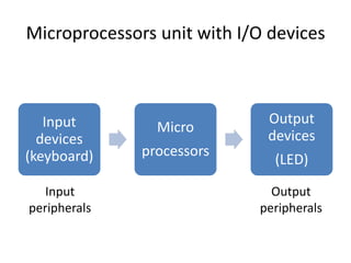
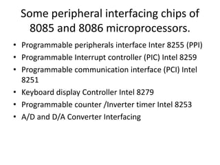
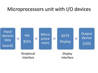
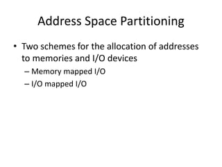
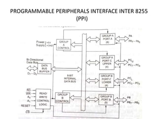
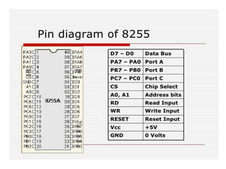
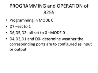
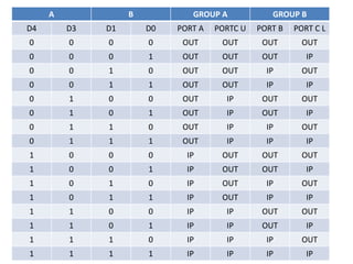
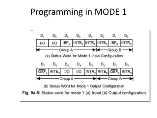
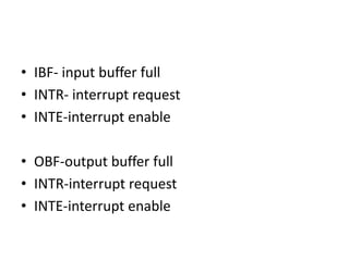
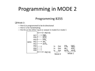
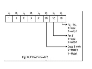
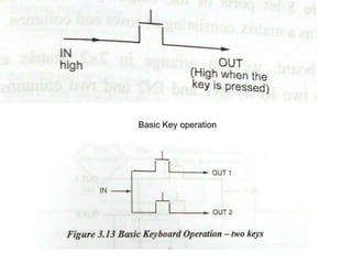
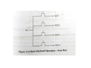
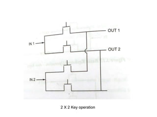
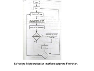
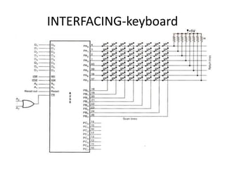
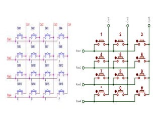
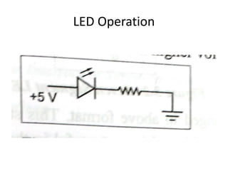
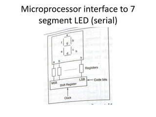
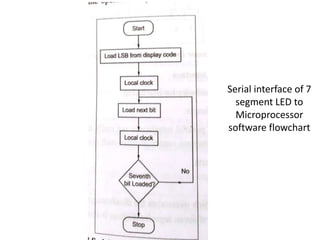
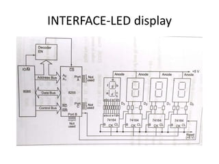
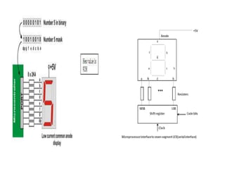
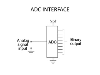
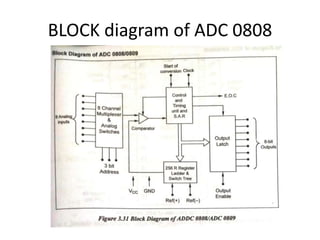
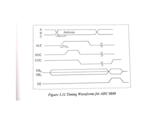
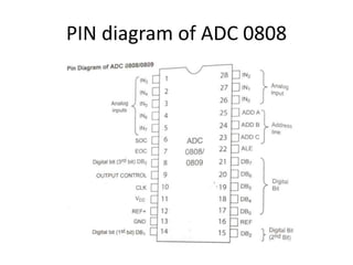
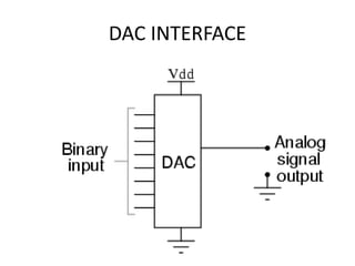
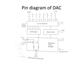
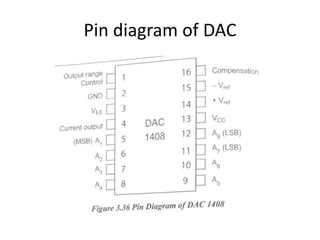
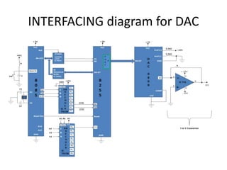
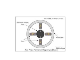
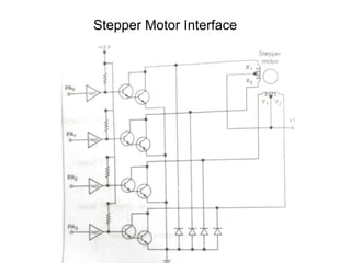
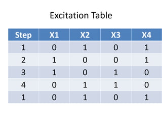
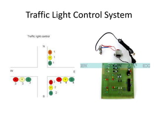
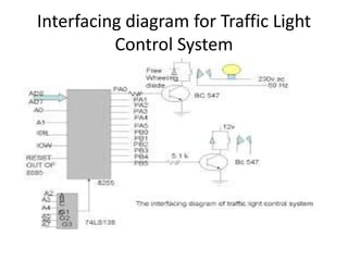
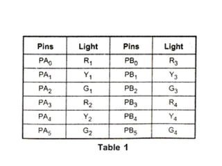
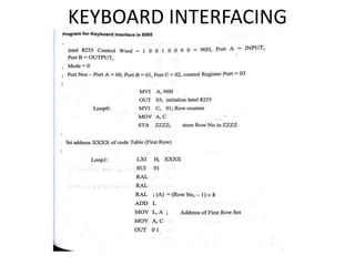
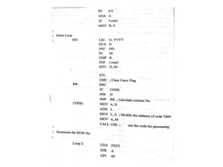
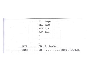
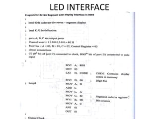
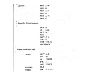
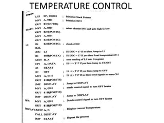
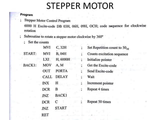
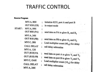
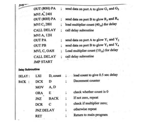
UNIT III PROGRAMMABLE PERIPHERAL INTERFACE 9
Introduction – Architecture of 8255, Keyboard interfacing, LED display –interfacing, ADC and
DAC interface, Temperature Control – Stepper Motor Control – Traffic Control interface.
The document discusses the Programmable Peripheral Interface 8255 (PPI), which is an I/O port chip used for interfacing I/O devices with microprocessors. It has 24 pins for I/O that are programmable in groups of 12 pins and has three distinct modes of operation. The PPI is commonly used in microprocessor labs for interfacing experiments and knowledge of it is essential for students. It describes the basic modes of operation and how to program the 8255.
The 8051 microcontroller has an 8-bit CPU, 4K ROM, 128 bytes RAM, two 16-bit timers, 32 I/O lines, and serial port. It uses an accumulator, B register, program status word and stack pointer along with arithmetic logic unit and instruction decoder to perform operations. The memory includes internal ROM, RAM, and external memory accessed via a 16-bit data pointer and program counter.
The document describes the 8051 microcontroller, its features which include 4 I/O ports, 2 timers, serial communication interface, and interrupts. It discusses the internal architecture such as memory organization, registers, and oscillator circuit. The document also provides details on the ports, timers, serial communication, and power modes of the 8051 microcontroller.
The document discusses asynchronous and synchronous serial communication using the 8251A USART chip. It describes the basics of serial communication including synchronous vs asynchronous transmission. It provides details on the components and functioning of the 8251A USART chip, including its transmitter, receiver, control logic and modem control sections. The chip allows for full-duplex serial communication and can operate in both synchronous and asynchronous modes. It converts parallel data from the microprocessor to serial data for transmission and vice versa on reception.
A microprocessor consists of a central processing unit and minimal additional components like registers, while a microcontroller includes more integrated components like memory, input/output pins and communication modules. Specifically, a microcontroller combines a microprocessor with RAM, ROM, timers and other peripherals onto a single chip, making it self-contained and suitable for embedded applications where cost, power and space are priorities. In contrast, a microprocessor's components are separate, providing more flexibility but also greater expense.
The document provides an overview of the 8051 microcontroller, including its history, architecture, memory organization, registers, I/O ports, and other key features. Some of the main points covered include:
- The 8051 was one of the earliest microcontrollers developed by Intel in 1980 and features 40 pins, 4K ROM, 128B RAM, and four 8-bit I/O ports.
- It has separate memory spaces for program and data memory up to 64KB each. Internal memory includes on-chip ROM and RAM, while external memory can be added.
- Special function registers (SFRs) are located at the top of internal RAM and include registers like ACC, B
The document discusses interfacing concepts and the Intel 8255 Programmable Peripheral Interface chip. It provides information on:
- Memory mapped I/O and I/O mapped I/O interfacing techniques.
- The 8255 PPI chip which has 3 8-bit I/O ports (Ports A, B, and C) that can be configured as input or output ports. It operates in I/O mode or Bit Set/Reset mode.
- Control word formats for configuring the ports in different modes like Mode 0, 1, and 2 for I/O mode and Bit Set/Reset mode.
- Example programs to initialize the 8255 ports using control words for different
The PIC microcontroller uses a Harvard architecture with separate program and data memories. It has a CPU with an ALU, memory unit, and control unit. The memory includes program memory to store instructions, data memory including registers for temporary data storage, and EEPROM for storing variables. It has advantages like a small instruction set, low cost, and built-in interfaces like I2C, SPI, and analog components.
Communication protocols in Embedded Systems. This presentation focused mainly on lower level protocols. Ideal for the beginner to build understanding on these protocols like I2C, USB, SPI etc.
The document discusses parallel data transfer using the 8155 Programmable Peripheral Interface chip. It describes how the 8155 allows microprocessors like the 8085 to interface with peripheral devices by providing programmable input/output ports and a timer. It has three 8-bit I/O ports (Ports A, B, and C) that can be programmed for simple or handshaked input/output. It also contains 256 bytes of RAM and a 14-bit programmable counter/timer. The 8155 is programmed by writing control words and data to its internal registers to configure the I/O ports and timer operation.
Microcontrollers are small computers that integrate RAM, ROM, I/O ports and other components onto a single chip. They are used in applications where cost, power and space are critical. The document compares microprocessors and microcontrollers, noting that microcontrollers have all components on one chip while microprocessors have separate chips. It then describes the typical internal blocks of a microcontroller, including the CPU, memory, I/O ports, timers and serial ports. Block diagrams show the connections between these internal components.
The document discusses serial port programming for the 8051 microcontroller. It describes how serial communication works using one bit at a time instead of parallel communication which transfers all bits at once. It explains the registers and pins used for serial communication on the 8051 including the serial data buffer (SBUF) register, serial control (SCON) register, and MAX232 voltage converter. It provides details on programming the 8051 for serial data transmission and reception, including using the TI and RI flags to indicate when data has been sent or received.
A microcontroller is a small computer on a single integrated circuit containing a processor core, memory, and programmable input/output peripherals. It is used in embedded systems to make decisions. The AVR ATmega8 is an 8-bit microcontroller based on Harvard architecture. It has 8KB of flash memory, 512B of EEPROM, and 1KB of SRAM. It contains peripherals like timers, PWM channels, ADC, and serial interfaces. The ATmega8 comes in PDIP and TQFP packages and uses three registers - DDRx, PORTx, and PINx - to communicate with its I/O ports.
The document discusses the minimum and maximum mode systems of the 8086 microprocessor. In minimum mode, the 8086 generates all control signals and a single processor is used. In maximum mode, an external bus controller chip generates control signals and multiple processors can be used. It describes the components, address latching, read and write cycles, and I/O interfacing for both minimum and maximum mode 8086 systems.
The document provides information on the architecture of the 8051 microcontroller. It describes the main features of the 8051 including an 8-bit CPU, 4Kbytes of on-chip program memory, 128 bytes of on-chip data RAM, two 16-bit timers/counters, and 32 I/O lines. It details the core components of the 8051 architecture including the ALU, accumulator, instruction decoder, registers, memory, and addressing modes. It explains the various registers like the program status word, stack pointer, data pointer, and program counter. It also covers the different types of instructions and addressing modes supported by the 8051 microcontroller.
The document discusses the Inter-Integrated Circuit (I2C) protocol. It was developed by Philips in the 1980s as a simpler way to connect peripherals in devices like TVs that previously used separate wiring for each component. I2C uses just two bidirectional lines (SCL for clock and SDA for data) and allows for multiple master and slave devices to communicate at speeds up to 3.4 Mbps using 7- or 10-bit addressing. Devices operate on a master-slave model where the master controls the bus by generating the clock signal and addressing slave devices to send or receive data.
1. The 8254 contains three independent 16-bit counters/timers that can be programmed to operate in different modes.
2. Each counter can be programmed to count from 1 to 65535 and has a programmable control word to select the operating mode.
3. The 8254 supports various timer modes like one-shot, continuous square wave, event counter, and software/hardware triggered one-shot for applications like timing, delay generation, and pulse width modulation.
The 8051 microcontroller has 128 bytes of internal RAM and 4Kbytes of internal ROM memory. It uses the same addresses for code and data but accesses the correct memory based on whether an operation is for code or data. The 128 bytes of internal RAM are organized into 4 banks of 32 bytes each. External memory can be added if more memory is needed for program code or variable data storage. The document also provides information on interfacing external program and data memory with the 8051 microcontroller.
8051 timer counter
Introduction
TMOD Register
TCON Register
Modes of Operation
Counters
The microcontroller 8051 has two 16 bit Timer/ Counter registers namely Timer 0 (T0) and Timer 1 (T1) .
When used as a “Timer” the microcontroller is programmed to count the internal clock pulse.
When used as a “Counter” the microcontroller is programmed to count external pulses.
Maximum count rate is 1/24 of the oscillator frequency.
The 8085 microprocessor uses several addressing modes to specify the operands in instructions. These include implied, immediate, direct, register, and register indirect addressing modes. Implied addressing mode does not specify operands as they are implicit in the instruction. Immediate addressing mode embeds the operand in the instruction itself. Direct addressing directly specifies the memory location of the operand. Register addressing uses register operands. Register indirect addressing specifies the operand address using a register pair like the HL register.
The document discusses the 8051 microcontroller. It begins by explaining why we need to learn about microprocessors and microcontrollers, noting that many modern devices are controlled by them. It then covers the basic components of a microprocessor/controller including the CPU, I/O, memory, timers, and interrupts. The rest of the document provides details on the 8051 microcontroller, including its architecture, memory structure, registers, ports and other features. It compares microprocessors and microcontrollers, and discusses how to choose between different microcontroller options for embedded systems.
This document describes the features and pin diagram of the 8085 microprocessor. It is an 8-bit processor that operates on a 5V power supply. It has 40 pins, including an 8-bit multiplexed address and data bus. The pin functions described include the address bus (A8-A15), data bus (AD0-AD7), control signals like RD and WR, status signals like IO/M and S0-S1, power supply pins VCC and VSS, interrupt pins like TRAP and INTR, externally initiated signals like INTA and RESET, serial I/O signals SOD and SID, and clock signals X1, X2, and CLK OUT.
This document provides an introduction and overview of microprocessors. It defines a microprocessor as a programmable VLSI chip that includes an ALU, registers, and control circuits. The document describes the basic components of a computer system including CPU, memory, and I/O. It provides a block diagram of the 8085 microprocessor architecture including its register array, ALU, instruction decoder, interrupt control, and serial I/O control. It also describes the address bus, data bus, status signals, control signals, and pin configuration of the 8085 microprocessor.
8259 Programmable Interrupt Controller by vijayVijay Kumar
The 8259A Programmable Interrupt Controller (PIC) is used to simplify the interrupt interface of 8088/8086 microprocessor systems. It can accept up to 8 interrupt requests and expand to 64 requests by cascading additional PICs. The PIC is programmable through initialization command words to configure operating modes and interrupt vector assignments. It also has operation command words to control interrupt masking, priorities, and acknowledgement.
This document provides an overview of the 8051 microcontroller architecture. It describes the basic components of the 8051 including 4K bytes of internal ROM, 128 bytes of internal RAM, four 8-bit I/O ports, two timers/counters, one serial interface, and other features. It also discusses the different addressing modes for 8051 assembly language programming including immediate, register, direct, register indirect, and external direct addressing.
This document discusses the programmable peripheral interface 8255 and its applications. It introduces the 8255 architecture and its operating modes, and provides examples of interfacing it with keyboards, LED displays, analog-to-digital converters, digital-to-analog converters, temperature sensors, stepper motors, and traffic light systems. Diagrams and code examples are given for each of these interfacing applications.
This document discusses the programmable peripheral interface 8255 and its applications. It describes the architecture and operating modes of the 8255 including bit set reset mode and I/O modes 0, 1, and 2. It then provides examples of interfacing the 8255 to keyboards, LED displays, analog to digital converters, digital to analog converters, temperature sensors, stepper motors, and traffic light systems. Diagrams and flowcharts are included to illustrate the interfacing between these peripheral devices and the microprocessor using the 8255.
Unit 3-PROGRAMMABLE PERIPHERAL INTERFACE-ME6702– MECHATRONICS Mohanumar S
This document discusses the programmable peripheral interface 8255 and its applications. It describes the architecture and operating modes of the 8255 including bit set reset mode and I/O modes 0, 1, and 2. It provides examples of interfacing the 8255 to keyboards, LED displays, analog to digital converters, digital to analog converters, temperature sensors, stepper motors, and traffic light systems. Diagrams and flowcharts illustrate the interfacing between these peripheral devices and a microprocessor using the 8255.
The document discusses various programmable peripheral interface chips used for input/output interfacing in microprocessor systems. It describes the architecture and operating modes of the 8255 Programmable Peripheral Interface chip, which has three 8-bit I/O ports that can be programmed for applications like keyboard interfacing, LED displays, analog-to-digital conversion, digital-to-analog conversion, temperature control, stepper motor control, and traffic light control systems. Circuit diagrams and software flowcharts are provided for different interfacing applications using the 8255 PPI chip.
MECHATRONICS-Unit 3-PROGRAMMABLE PERIPERAL INTERFACE.pptCHANDRA KUMAR S
This document discusses various programmable peripheral interface chips used for input/output interfacing in microprocessor systems. It describes the architecture and programming of the 8255 Programmable Peripheral Interface chip, which allows flexible configuration of three 8-bit ports. Application examples discussed include interfacing keyboards, LED displays, analog-to-digital converters, digital-to-analog converters, temperature sensors, and stepper motors. Memory mapped and I/O mapped addressing schemes for connecting peripherals are also summarized.
This document provides information on peripheral interfacing in microprocessors. It discusses memory interfacing and I/O interfacing, and some of the peripheral devices developed by Intel like the 8255 parallel communication interface, 8251 serial communication interface, 8254 programmable timer, and 8257 DMA controller. It then describes serial and parallel communication interfaces. It provides details on the 8255 programmable peripheral interface and its operating modes. Finally, it discusses digital to analog converters, applications of the 8254 timer/counter, and analog to digital converters.
This document discusses various programmable devices used in 8085-based systems, including the 8255 Programmable Peripheral Interface (PPI), 8251 Programmable Communication Interface, 8259 Programmable Interrupt Controller, and 8279 Programmable Keyboard/Display Interface. It provides details on the pinouts, internal blocks, operating modes, and interfacing of each device. The 8255 PPI allows programming of I/O ports and is used for data transfer between the processor and I/O devices. The 8251 provides serial communication capabilities. The 8259 manages interrupt requests from peripherals. And the 8279 interfaces keyboards and displays for microprocessor systems.
MicroProcessors and MicroControllersUnit3deepakdmaat
This document provides an overview of Unit III - I/O Interfacing in a syllabus. It discusses various topics related to interfacing memory and I/O devices, including parallel communication interfaces like the 8255 PPI chip, serial communication interfaces like the 8251 USART, and analog interfaces such as A/D converters, D/A converters, and timers. It also lists some case studies and applications that will be covered, including traffic light control, LED displays, LCD displays, keyboard/display interfaces, and alarm controllers.
This document discusses memory and I/O interfacing in microprocessors. It describes the parallel communication interface 8255 which allows a microprocessor to interface with peripheral devices. The 8255 has three 8-bit ports that can be programmed to work in different modes like basic I/O, strobed I/O, and bidirectional modes. It reduces external logic needed for interfacing and can be programmed to perform specific functions through control words. The document also briefly mentions other programmable peripheral devices like serial interface 8251, timer 8254, and interrupt controller 8259.
This document describes an electronic toll collection system using RFID technology. It consists of an ATmega328 microcontroller, LCD display, RFID reader and tags, motor driver IC and DC motor. The RFID tag is read and the stored balance is checked. If sufficient, the balance is deducted and the motor opens the gate. This system allows automatic toll collection without stopping, reducing congestion. It provides transparency while decreasing operating costs for toll operators.
8255 ppi students material for ppi mpmc studySirisha Vamsi
The document discusses the 8255 Programmable Peripheral Interface chip. It is used to interface I/O devices with microprocessors and allows parallel data transfer between slow peripheral devices and the processor. The 8255 has 3 ports - Port A and B are 8-bit ports, while Port C can be split into two 4-bit ports. The ports can be programmed in 3 different modes to control data transfer and handshaking. Control words are used to specify the I/O functions and mode of each port.
The 8255 is a programmable peripheral interface chip that connects microprocessors to input and output devices. It has three 8-bit ports (A, B, C) that can be programmed to operate in different I/O modes to interface with devices. Port A can be programmed in modes 0, 1, and 2 while ports B and C can be programmed in modes 0 and 1 only. The 8255 uses control logic and group control blocks to interface the ports with the microprocessor data and control buses according to instructions to simplify interfacing with multiple I/O devices.
The document discusses programmable logic controllers (PLCs). It defines PLCs as digitally operating electronic devices that use programmable memory to implement logic functions to control machines and processes through digital and analog inputs and outputs. The document outlines the history and evolution of PLCs from relay-based to solid-state designs. It describes typical PLC architectures, components, programming languages like ladder logic, applications in machine control and other industrial processes, and advantages of PLCs over traditional electromechanical controls.
The document discusses various input/output interfacing components used with microprocessors, including parallel and serial communication interfaces, analog to digital and digital to analog converters, timers, and interrupt controllers. It describes the 8255 parallel interface chip, 8251 serial interface chip, and programming of ports and modes. Memory interfacing is also covered briefly. Application examples discussed include traffic light control, LED displays, and keyboard/display interfaces.
ijfij fi fjijfij fijfijif if iji j iijfij fi fjijfij fijfijif if iji j iijfij fi fjijfij fijfijif if iji j iijfij fi fjijfij fijfijif if iji j iijfij fi fjijfij fijfijif if iji j iijfij fi fjijfij fijfijif if iji j iijfij fi fjijfij fijfijif if iji j iijfij fi fjijfij fijfijif if iji j iijfij fi fjijfij fijfijif if iji j iijfij fi fjijfij fijfijif if iji j iijfij fi fjijfij fijfijif if iji j iijfij fi fjijfij fijfijif if iji j iijfij fi fjijfij fijfijif if iji j iijfij fi fjijfij fijfijif if iji j iijfij fi fjijfij fijfijif if iji j iijfij fi fjijfij fijfijif if iji j iijfij fi fjijfij fijfijif if iji j iijfij fi fjijfij fijfijif if iji j iijfij fi fjijfij fijfijif if iji j iijfij fi fjijfij fijfijif if iji j iijfij fi fjijfij fijfijif if iji j iijfij fi fjijfij fijfijif if iji j iijfij fi fjijfij fijfijif if iji j iijfij fi fjijfij fijfijif if iji j iijfij fi fjijfij fijfijif if iji j iijfij fi fjijfij fijfijif if iji j iijfij fi fjijfij fijfijif if iji j iijfij fi fjijfij fijfijif if iji j iijfij fi fjijfij fijfijif if iji j iijfij fi fjijfij fijfijif if iji j iijfij fi fjijfij fijfijif if iji j iijfij fi fjijfij fijfijif if iji j iijfij fi fjijfij fijfijif if iji j iijfij fi fjijfij fijfijif if iji j iijfij fi fjijfij fijfijif if iji j iijfij fi fjijfij fijfijif if iji j iijfij fi fjijfij fijfijif if iji j iijfij fi fjijfij fijfijif if iji j iijfij fi fjijfij fijfijif if iji j iijfij fi fjijfij fijfijif if iji j iijfij fi fjijfij fijfijif if iji j iijfij fi fjijfij fijfijif if iji j iijfij fi fjijfij fijfijif if iji j iijfij fi fjijfij fijfijif if iji j iijfij fi fjijfij fijfijif if iji j iijfij fi fjijfij fijfijif if iji j iijfij fi fjijfij fijfijif if iji j i
The document discusses peripheral interfacing with various ICs like 8255, 8259, 8254, 8279, and A/D and D/A converters. It provides details about the architecture, configuration, and interfacing of these ICs with 8085 and 8051 microprocessors. Specifically, it describes the 8255 PPI chip, its pin diagram, block diagram, modes of operation including bit set/reset mode and I/O modes 0, 1, and 2. It also discusses memory mapped I/O versus I/O mapped I/O and synchronous versus asynchronous data transfers.
This document describes a monitoring, protection, and control module for a radar transmitter. The module monitors key transmitter parameters, protects the system by triggering faults if parameters exceed thresholds, and controls the transmitter's on/off sequencing. It uses comparators to detect parameter faults, a microcontroller for control and interfacing, an ADC to convert analog signals, and an LCD for output display. The design aims to safely monitor and protect the expensive transmitter components.
The document provides background information on programmable logic controllers (PLCs). It discusses the origin of PLCs in the 1960s as an alternative to relay-based control systems. It then covers the key components of PLCs including the processor, memory, I/O modules, and power supply. The document also discusses PLC programming and applications in various industrial sectors.
The 8255 Programmable Peripheral Interface chip is used to interface I/O devices with microprocessors. It has 3 ports - Port A, Port B, and Port C. Port C has two independent 4-bit ports. The 8255 can operate in I/O mode or Bit Set/Reset mode. In I/O mode, the ports can be configured for basic, strobed, or bidirectional I/O. The mode and port configurations are set using control words written to the chip.
Similar to UNIT III PROGRAMMABLE PERIPHERAL INTERFACE (20)
This document provides an introduction to value education, including:
- The meaning of value education as enabling understanding of what is valuable for human happiness through transformation from animal to human consciousness.
- The need for value education to correctly identify aspirations, understand universal human values, and develop a holistic perspective.
- The scope and content of value education, which should include all dimensions of human living at individual, family, society and nature levels.
- The process of value education begins with self-exploration to understand desires, programs, and realize that right understanding and relationships are basic human needs.
The document discusses the relationship between the self ("I") and the body in a human being. It states that a human being is a co-existence of the self and body, with an exchange of information between the two. It also discusses that the self's needs are for happiness and fulfillment, while the body's needs are for physical facilities like food and shelter. Maintaining harmony between the self and body requires fulfilling both their needs through right understanding, regulation of the self, and ensuring overall health of the body.
The document discusses family structures and relationships. It defines the family and outlines key functions of families, including childcare, economic support, caring for elders, and teaching cultural/religious values. It classifies families based on factors like marriage type (monogamous, polygamous, polyandrous), residence patterns, ancestry, and size/generation structure. Maintaining harmony in family relations requires commitment, respect, trust and understanding different personalities. Respecting each member, spending quality time together, and resolving conflicts through dialogue rather than disconnect are emphasized.
The document discusses the four orders of nature: physical, plant, animal, and human. It argues that there is a relationship of mutual fulfillment between the orders, where each order supports the others. So far, the physical, plant, and animal orders fulfill each other and humans. However, humans have yet to fully achieve mutual fulfillment due to a lack of right understanding leading to problems like pollution. The document aims to explore the inherent design of nature and existence.
This document discusses implications of a holistic understanding of harmony on professional ethics. It explores how natural human values like trust and respect are innate and do not depend on time, place, or beliefs. It argues this provides a basis for universal human values and ethical conduct. It discusses implications like transition to happiness at individual and societal levels through value-based living. It advocates for humanistic education and constitution to develop right understanding and move towards a holistic alternative that is sustainable and fulfills human aspirations. Finally, it discusses issues in professional ethics today and need for developing ethical competence through value education.
UNIT V ACTUATORS AND MECHATRONIC SYSTEM DESIGN ravis205084
UNIT V ACTUATORS AND MECHATRONIC SYSTEM DESIGN 9
Types of Stepper and Servo motors – Construction – Working Principle – Advantages and
Disadvantages. Design process-stages of design process – Traditional and Mechatronics design
concepts – Case studies of Mechatronics systems – Pick and place Robot – Engine Management
system – Automatic car park barrier.
Introduction to Mechatronics – Systems – Concepts of Mechatronics approach – Need for
Mechatronics – Emerging areas of Mechatronics – Classification of Mechatronics. Sensors and
Transducers: Static and dynamic Characteristics of Sensor, Potentiometers – LVDT – Capacitance
sensors – Strain gauges – Eddy current sensor – Hall effect sensor – Temperature sensors – Light
sensors
Unit 5 -cellular manufacturing & fmsravis205084
Group Technology(GT),Part Families–Parts Classification and coding–Simple Problems in Opitz Part
Coding system–Production flow Analysis–Cellular Manufacturing–Composite part concept–Types of
Flexibility - FMS – FMS Components – FMS Application & Benefits – FMS Planning and Control–
Quantitative analysis in FMS
This document discusses various CAD standards including:
1. Graphic standards like GKS and OpenGL that allow for portability of geometric models between hardware and software.
2. Data exchange standards like IGES and STEP that define neutral formats for transferring CAD data between different systems.
3. Communication standards like LANs and WANs that enable the transfer of CAD data between networked computer systems.
The standards aim to facilitate interoperability for CAD/CAM data by providing common languages and specifications for graphics, file formats, and network communication.
Unit 1 INTRODUCTION (COMPUTER AIDED DESIGN AND MANUFACTURING )ravis205084
UNIT I INTRODUCTION 9
Product cycle- Design process- sequential and concurrent engineering- Computer aided design –
CAD system architecture- Computer graphics – co-ordinate systems- 2D and 3D transformationshomogeneous
coordinates
- Line drawing -Clipping- viewing transformation-Brief introduction to CAD
and CAM – Manufacturing Planning, Manufacturing control- Introduction to CAD/CAM –CAD/CAM
concepts ––Types of production - Manufacturing models and Metrics – Mathematical models of
Production Performance
Embedded machine learning-based road conditions and driving behavior monitoringIJECEIAES
Car accident rates have increased in recent years, resulting in losses in human lives, properties, and other financial costs. An embedded machine learning-based system is developed to address this critical issue. The system can monitor road conditions, detect driving patterns, and identify aggressive driving behaviors. The system is based on neural networks trained on a comprehensive dataset of driving events, driving styles, and road conditions. The system effectively detects potential risks and helps mitigate the frequency and impact of accidents. The primary goal is to ensure the safety of drivers and vehicles. Collecting data involved gathering information on three key road events: normal street and normal drive, speed bumps, circular yellow speed bumps, and three aggressive driving actions: sudden start, sudden stop, and sudden entry. The gathered data is processed and analyzed using a machine learning system designed for limited power and memory devices. The developed system resulted in 91.9% accuracy, 93.6% precision, and 92% recall. The achieved inference time on an Arduino Nano 33 BLE Sense with a 32-bit CPU running at 64 MHz is 34 ms and requires 2.6 kB peak RAM and 139.9 kB program flash memory, making it suitable for resource-constrained embedded systems.
Harnessing WebAssembly for Real-time Stateless Streaming PipelinesChristina Lin
Traditionally, dealing with real-time data pipelines has involved significant overhead, even for straightforward tasks like data transformation or masking. However, in this talk, we’ll venture into the dynamic realm of WebAssembly (WASM) and discover how it can revolutionize the creation of stateless streaming pipelines within a Kafka (Redpanda) broker. These pipelines are adept at managing low-latency, high-data-volume scenarios.
A SYSTEMATIC RISK ASSESSMENT APPROACH FOR SECURING THE SMART IRRIGATION SYSTEMSIJNSA Journal
The smart irrigation system represents an innovative approach to optimize water usage in agricultural and landscaping practices. The integration of cutting-edge technologies, including sensors, actuators, and data analysis, empowers this system to provide accurate monitoring and control of irrigation processes by leveraging real-time environmental conditions. The main objective of a smart irrigation system is to optimize water efficiency, minimize expenses, and foster the adoption of sustainable water management methods. This paper conducts a systematic risk assessment by exploring the key components/assets and their functionalities in the smart irrigation system. The crucial role of sensors in gathering data on soil moisture, weather patterns, and plant well-being is emphasized in this system. These sensors enable intelligent decision-making in irrigation scheduling and water distribution, leading to enhanced water efficiency and sustainable water management practices. Actuators enable automated control of irrigation devices, ensuring precise and targeted water delivery to plants. Additionally, the paper addresses the potential threat and vulnerabilities associated with smart irrigation systems. It discusses limitations of the system, such as power constraints and computational capabilities, and calculates the potential security risks. The paper suggests possible risk treatment methods for effective secure system operation. In conclusion, the paper emphasizes the significant benefits of implementing smart irrigation systems, including improved water conservation, increased crop yield, and reduced environmental impact. Additionally, based on the security analysis conducted, the paper recommends the implementation of countermeasures and security approaches to address vulnerabilities and ensure the integrity and reliability of the system. By incorporating these measures, smart irrigation technology can revolutionize water management practices in agriculture, promoting sustainability, resource efficiency, and safeguarding against potential security threats.
ACEP Magazine edition 4th launched on 05.06.2024Rahul
This document provides information about the third edition of the magazine "Sthapatya" published by the Association of Civil Engineers (Practicing) Aurangabad. It includes messages from current and past presidents of ACEP, memories and photos from past ACEP events, information on life time achievement awards given by ACEP, and a technical article on concrete maintenance, repairs and strengthening. The document highlights activities of ACEP and provides a technical educational article for members.
Using recycled concrete aggregates (RCA) for pavements is crucial to achieving sustainability. Implementing RCA for new pavement can minimize carbon footprint, conserve natural resources, reduce harmful emissions, and lower life cycle costs. Compared to natural aggregate (NA), RCA pavement has fewer comprehensive studies and sustainability assessments.
Understanding Inductive Bias in Machine LearningSUTEJAS
This presentation explores the concept of inductive bias in machine learning. It explains how algorithms come with built-in assumptions and preferences that guide the learning process. You'll learn about the different types of inductive bias and how they can impact the performance and generalizability of machine learning models.
The presentation also covers the positive and negative aspects of inductive bias, along with strategies for mitigating potential drawbacks. We'll explore examples of how bias manifests in algorithms like neural networks and decision trees.
By understanding inductive bias, you can gain valuable insights into how machine learning models work and make informed decisions when building and deploying them.
Literature Review Basics and Understanding Reference Management.pptxDr Ramhari Poudyal
Three-day training on academic research focuses on analytical tools at United Technical College, supported by the University Grant Commission, Nepal. 24-26 May 2024
KuberTENes Birthday Bash Guadalajara - K8sGPT first impressionsVictor Morales
K8sGPT is a tool that analyzes and diagnoses Kubernetes clusters. This presentation was used to share the requirements and dependencies to deploy K8sGPT in a local environment.
International Conference on NLP, Artificial Intelligence, Machine Learning an...gerogepatton
International Conference on NLP, Artificial Intelligence, Machine Learning and Applications (NLAIM 2024) offers a premier global platform for exchanging insights and findings in the theory, methodology, and applications of NLP, Artificial Intelligence, Machine Learning, and their applications. The conference seeks substantial contributions across all key domains of NLP, Artificial Intelligence, Machine Learning, and their practical applications, aiming to foster both theoretical advancements and real-world implementations. With a focus on facilitating collaboration between researchers and practitioners from academia and industry, the conference serves as a nexus for sharing the latest developments in the field.
We have compiled the most important slides from each speaker's presentation. This year’s compilation, available for free, captures the key insights and contributions shared during the DfMAy 2024 conference.
2. Content
• Introduction
• Architecture of 8255
• Keyboard interfacing
• LED display –interfacing
• ADC and DAC interface
• Temperature Control
• Stepper Motor Control
• Traffic Control interface
3. Introduction
• To communicate with the outside world,
microprocessor use peripherals (I/O devices)
• Input devices – Keyboards, A/D converters
etc.,
• Output devices – CRT, Printers, LEDs etc.,
• Peripherals are connected to the
microprocessors through electronic circuit
known as interfacing circuits.
4. Microprocessors unit with I/O devices
Input
devices
(keyboard)
Micro
processors
Output
devices
(LED)
Input
peripherals
Output
peripherals
5. • Some of the general purpose interfacing devices
– I/O ports
– Programmable peripherals interface (PPI)
– DMA controllers(Direct memory access)
– Interrupt controller
• Some of the special purpose interfacing devices
– CRT controller
– Keyboard
– Display
– Floppy Disc controllers
6. Some peripheral interfacing chips of
8085 and 8086 microprocessors.
• Programmable peripherals interface Inter 8255 (PPI)
• Programmable Interrupt controller (PIC) Intel 8259
• Programmable communication interface (PCI) Intel
8251
• Keyboard display Controller Intel 8279
• Programmable counter /Inverter timer Intel 8253
• A/D and D/A Converter Interfacing
7. Microprocessors unit with I/O devices
Input
devices
(key
board)
PPI
8255
Micro
proce
ssors
8279
Display
Output
device
(LED)
Peripheral
Interface
Display
Interface
8. Address Space Partitioning
• Two schemes for the allocation of addresses
to memories and I/O devices
– Memory mapped I/O
– I/O mapped I/O
9. Memory mapped I/O
• It has only one address space
• Address space is defined as the set of all
possible addresses that a microprocessor can
generate
• Some addresses assigned to memories and
Some addresses to I/O devices
• Memory locations are assigned with addresses
from 8000 to 84FF
• It is suitable for small system.
10. I/O mapped I/O scheme
• In this scheme, addresses assigned to
memories locations can also be assigned to
I/O devices
• When the signal is high, then address on the
address bus is for an I/O devices
• When the signal is low, then address on the
address bus is for memory locations.
11. I/O mapped I/O scheme
• Two extra instruction IN and OUT are used to
address I/O devices.
• The IN instruction is used to read the data of
an input devices.
• The OUT instruction is used to send the data
of an input devices.
• This scheme is suitable for a large system.
15. I/O Mode
• The 8255 has the following 3 modes of
operation
– Mode 0 – Simple Input/output
– Mode 1 – Input / Output with the Handshake or
strobed
– Mode 2 – Bi-directional I/O
16. I/O Mode
Mode 0 – Simple Input/output
– Port A and port B are used as two simple 8-bit I/O
port
– Port C as two 4-bit port
• Features
– Outputs are latched
– Inputs are buffered not latched
– Ports do not have handshake or interrupt
capability
17. I/O Mode
• Mode 1 – Input / Output with the Handshake
– Input or output data transfer is controlled by
handshaking signals.
– Handshaking signals are used to transfer data
between devices whose data transfer speeds are
not same.
– Port A and Port B are designed to operate with the
Port C.
– When Port A and Port B are programmed in Mode
1, 6 pins of port C is used for their control.
18. I/O Mode
• D0-D7 data bus
– bi directional, tri state data bus line
– It is used to transfer data and control word from
8085 to 8255
• RD (Read)
– When this pin is low, the CPU can read data in the
port or status word through the data buffer
• WR (write)
– When this pin is low, the CPU can write data in the
port or in the control register through the data
buffer
19. I/O Mode
• Mode 2 – Bi-directional I/O
• Port A can be programmed to operate as a
bidirectional port.
• The mode 2 operation is only for port A
• When port A is programmed in Mode 2, the
Port B can be used in either Mode 1 or Mode
0.
• Mode 2 operation the port a is controlled by
PC3 to PC7 of port C.
22. PROGRAMMING and OPERATION of
8255
• Programming in MODE 0
• D7 –set to 1
• D6,D5,D2- all set to 0 –MODE 0
• D4,D3,D1 and D0- determine weather the
corresponding ports are to configured as input
or output
23. A B GROUP A GROUP B
D4 D3 D1 D0 PORT A PORTC U PORT B PORT C L
0 0 0 0 OUT OUT OUT OUT
0 0 0 1 OUT OUT OUT IP
0 0 1 0 OUT OUT IP OUT
0 0 1 1 OUT OUT IP IP
0 1 0 0 OUT IP OUT OUT
0 1 0 1 OUT IP OUT IP
0 1 1 0 OUT IP IP OUT
0 1 1 1 OUT IP IP IP
1 0 0 0 IP OUT OUT OUT
1 0 0 1 IP OUT OUT IP
1 0 1 0 IP OUT IP OUT
1 0 1 1 IP OUT IP IP
1 1 0 0 IP IP OUT OUT
1 1 0 1 IP IP OUT IP
1 1 1 0 IP IP IP OUT
1 1 1 1 IP IP IP IP
53. TEMPERATURE CONTROL
• Temperature sensor –convert temp to
electrical signal by thermistor
• Transducer convert physical data into
electrical signal
• Physical data –temp, light, flow, speed etc…
• LM34 & LM35 –temperature sensor by
NATIONAL SEMICONDUCTOR CO-OPERATION
54. • LM34
• Output voltage is
linearly proportional to
Fahrenheit temp
• No external calibration
• 10mV for each degree
of Fahrenheit temp
• LM35
• Output voltage is
linearly proportional to
Celsius temp
• No external calibration
• 10mV for each degree
of Centigrate temp
55.
56. STEPPER MOTOR CONTROL interface
• Digital motor used to translate electrical pulse
into mechanical movement
• Center tap winding connected to 12 V supply
• Motor can be excited by grounding four
terminals of the two windings
• ROTOR-Stepper motor has permanent magnet
rotor .It is also known as shaft
• STEP ANGLE-It is minimum degree of rotation
associated with a single step
60. Traffic Light Control System
• Allow traffic from W to E and E to W transition
for 20 seconds
• Give transition period of 5 seconds (yellow
bulbs ON)
• Allow traffic from N to s and S to n for 20
seconds
• Give transition period of 5 seconds (yellow
bulbs ON)
• Repeat the process