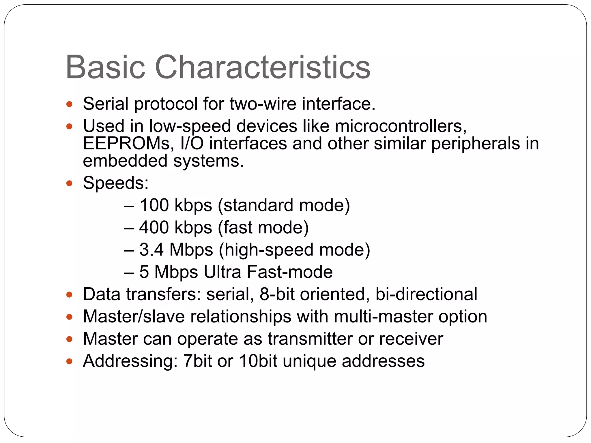
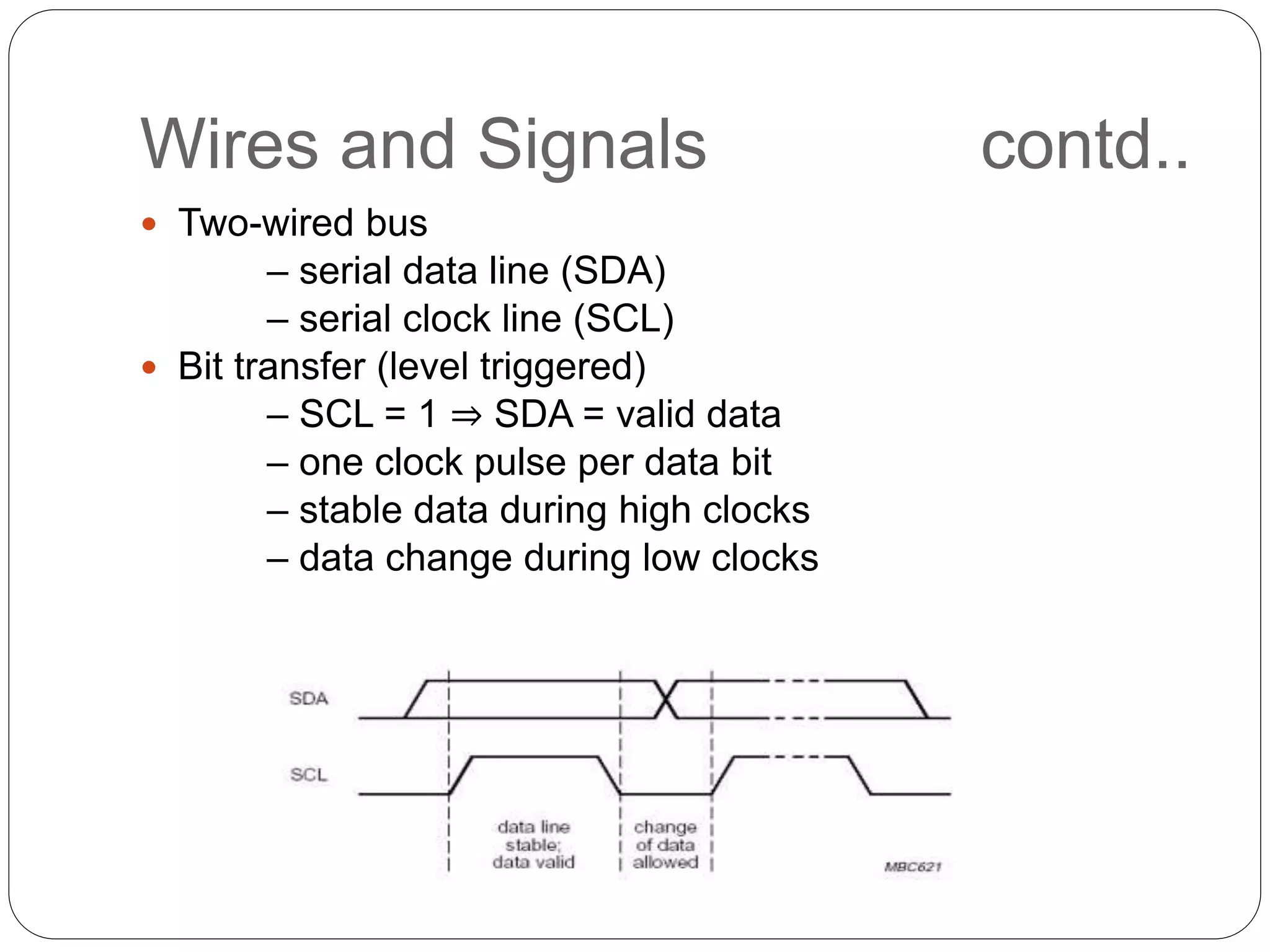
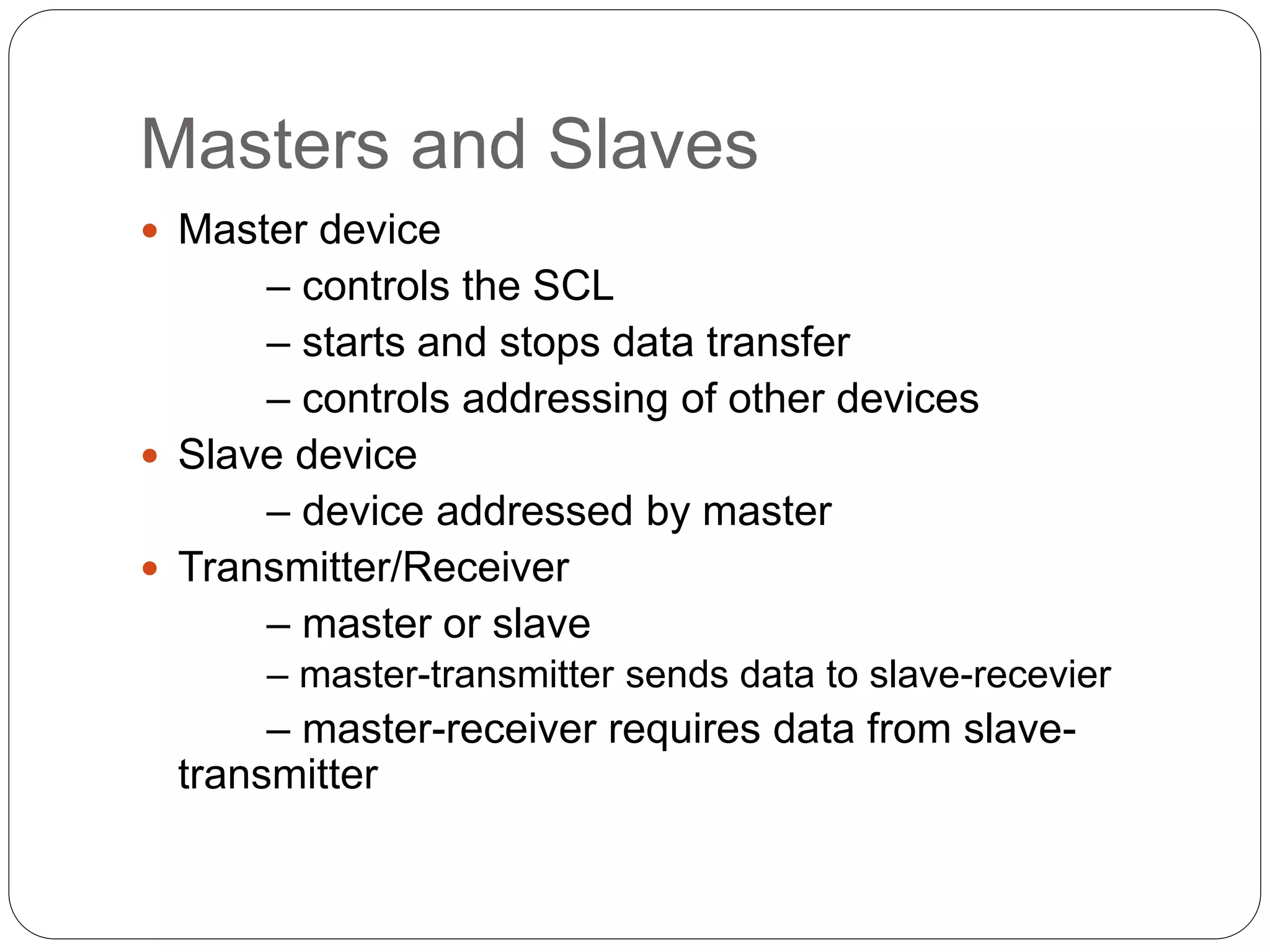
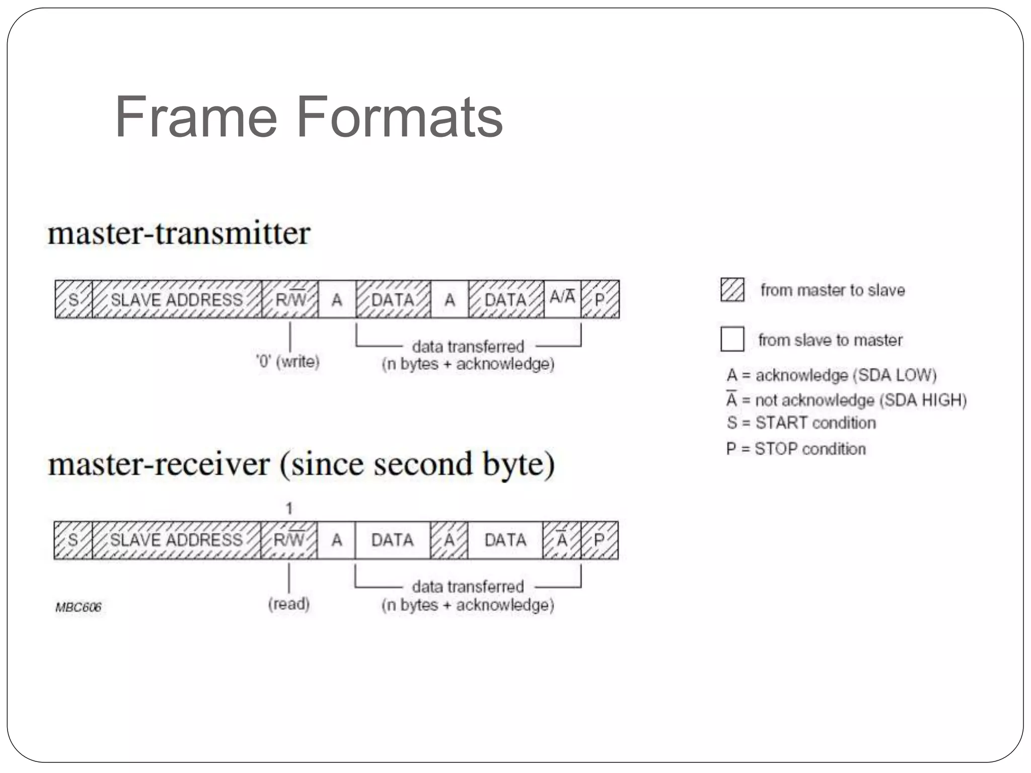
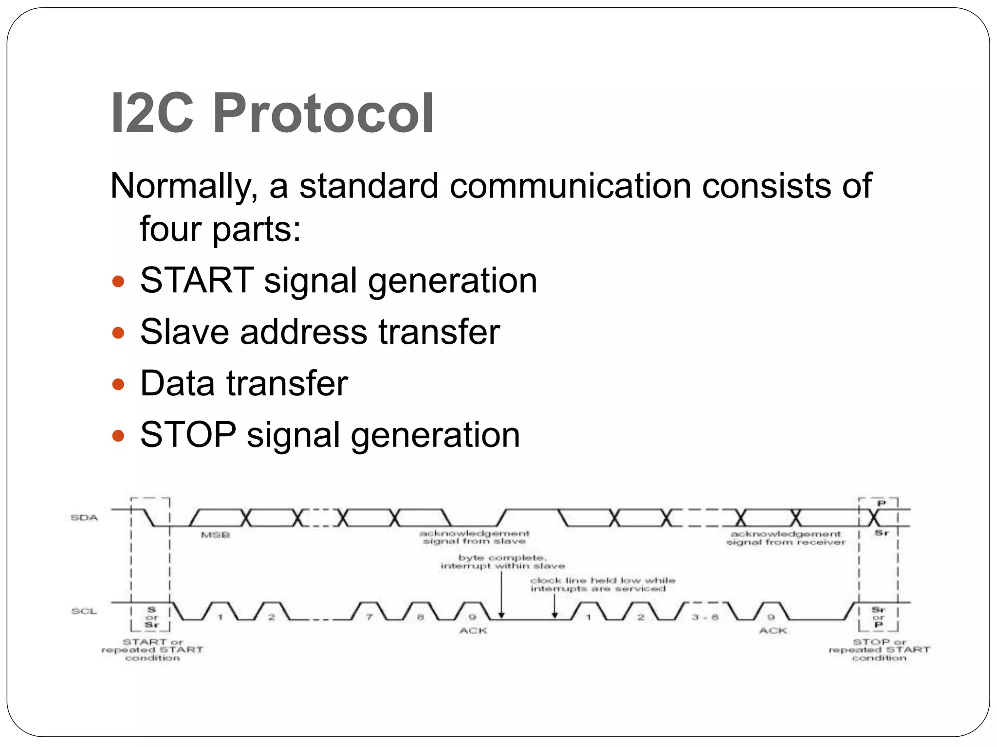
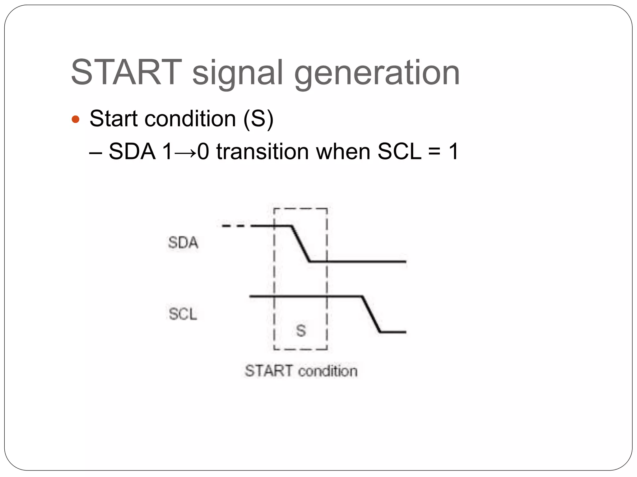
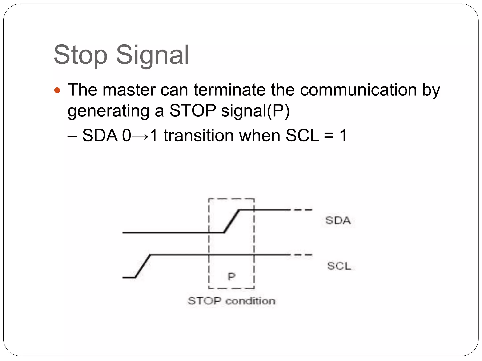
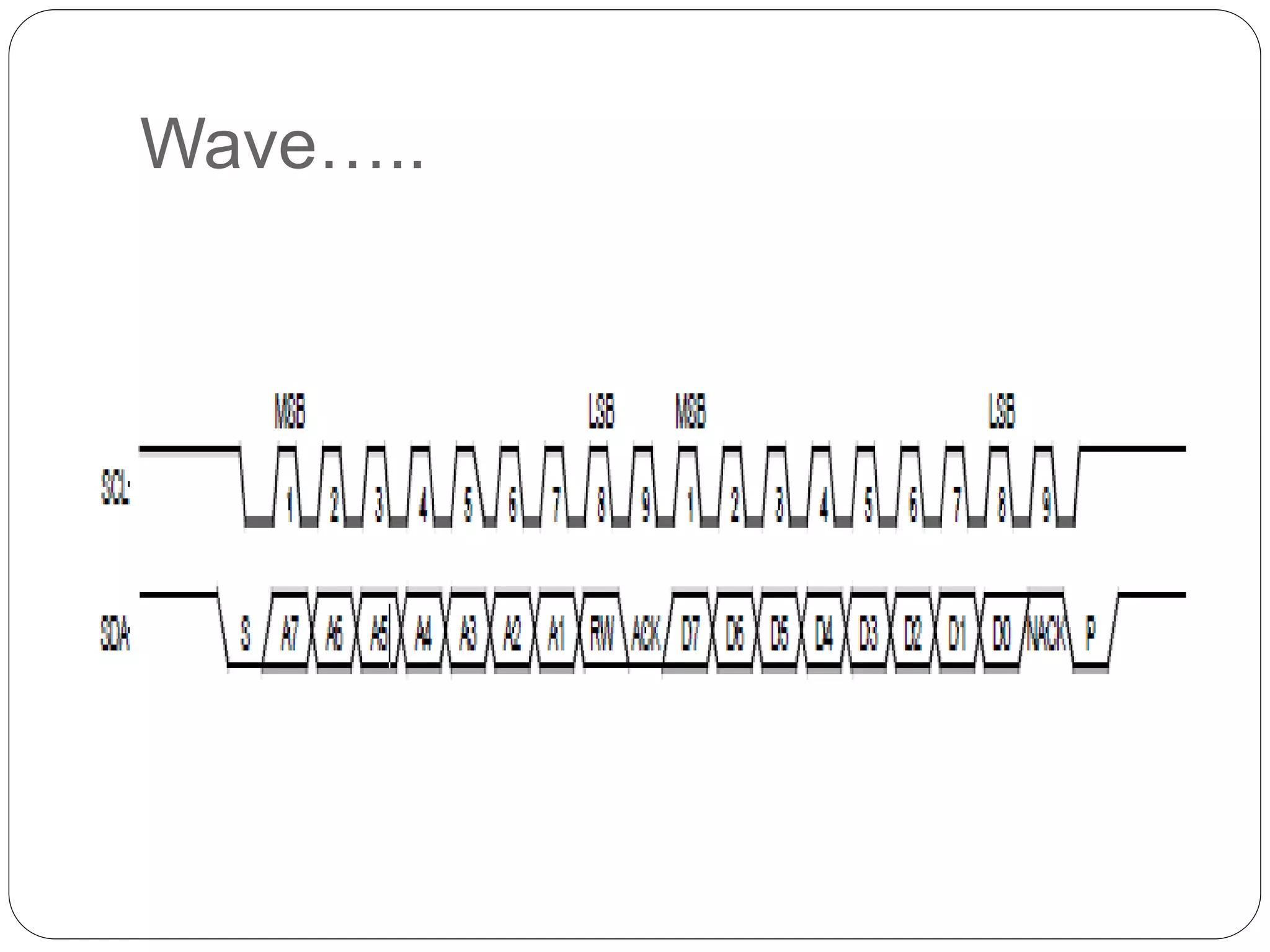
By-
Akhil Srivastava
Ajay Sharma
I2C Bus
Basic Characteristics
 Serial protocol for two-wire interface.
 Used in low-speed devices like microcontrollers,
EEPROMs, I/O interfaces and other similar peripherals in
embedded systems.
 Speeds:
– 100 kbps (standard mode)
– 400 kbps (fast mode)
– 3.4 Mbps (high-speed mode)
– 5 Mbps Ultra Fast-mode
 Data transfers: serial, 8-bit oriented, bi-directional
 Master/slave relationships with multi-master option
 Master can operate as transmitter or receiver
 Addressing: 7bit or 10bit unique addresses
Wires and Signals contd..
 Two-wired bus
– serial data line (SDA)
– serial clock line (SCL)
 Bit transfer (level triggered)
– SCL = 1 ⇒ SDA = valid data
– one clock pulse per data bit
– stable data during high clocks
– data change during low clocks
Wires and Signals
 Signals –
 Start
 Stop
 Ack
 Not Ack
 Bus state
– free/Idle … after stop and before next Start.
(an IDLE bus condition is defined as having
both SDA and SCL high)
– busy … after Start and before next stop
Masters and Slaves
 Master device
– controls the SCL
– starts and stops data transfer
– controls addressing of other devices
 Slave device
– device addressed by master
 Transmitter/Receiver
– master or slave
– master-transmitter sends data to slave-recevier
– master-receiver requires data from slave-
transmitter
Frame Formats
I2C Protocol
Normally, a standard communication consists of
four parts:
 START signal generation
 Slave address transfer
 Data transfer
 STOP signal generation
START signal generation
 Start condition (S)
– SDA 1→0 transition when SCL = 1
Slave Address Transfer
 Slave address bits are transferred after start condition
 Transmission is byte oriented
 Most significant bit (MSB) first
 8 pulses for data bits are followed by one pulse for
ack. bit
{ 7 bits + R/W+ one acknowledge bit }
 Ack by slave at 9th SCL clk cycle by pulling SDA low.
 Slave address is also datum
– first byte transferred
– during the first byte transfer:
• master is transmitter
• addressed slave is receiver
Data Transfer
 Data transfer starts after successful slave
addressing.
 Data bits are generated by transmitter as SCL
pulses
 9-th pulse:
– transmitter releases SDA
– receiver must hold SDA low in order to ack.
received data
– slave must release SDA after ack. bit
(allows master to end frame)
Stop Signal
 The master can terminate the communication by
generating a STOP signal(P)
– SDA 0→1 transition when SCL = 1
Wave…..
Clock stretching
 Clock stretching is a feature of some slaves.
 If no slaves in a system can stretch the clock
(hold SCL LOW),
 the master need not be designed to handle this
procedure.
 The transaction cannot continue until the line is
released HIGH again.
 Clock stretching is optional
 most slave devices do not include an SCL driver
so they are unable to stretch the clock.
Clock stretching ….Contd
 Example- On the byte level, a device may be able to
receive bytes of data at a fast rate, but needs more time to
store a received byte or prepare another byte to be
transmitted. Slaves can then hold the SCL line LOW after
reception and acknowledgment of a byte to force the
master into a wait state until the slave is ready for the next
byte transfer in a type of handshake procedure
Multiple Masters
 more bus controllers can be connected
 several masters can start frame at once
 synchronization needed on SCL
 arbitration needed on SDA
 using wired-AND connection to SCL/SDA
Synchronization on SCL
 frame started SCL = 1
 first 10 transition (*)
– involved masters restart their
clocks
– master holds 0 until its low-
period is over
 master finished its low-period
– releases SCL
– SCL = 0 switches to wait
state, waits for SCL = 1
– SCL = 1 or waiting finished
starts counting high-period
 first master finished its high-period
– sets SCL = 0
– equivalent to (*) state
Synchronized Clocks
 low-period
– determined by max{low-periods of involved
masters}
 high-period
– determined by min{high-periods of involved
masters}
Arbitration on SDA
 frame started, SCL synchronized high periods = valid data
 each master generates its data
 master aborts if there is another level on SDA than it
generates
it loses arbitration, releases SDA and tries again when
bus is free
Notes on Arbitration
 can continue for many bits
 addresses are compared at first stage
 if the same slave is addressed in the same mode (R/W):
– masters are transmitters data-bits are compared
– masters are receivers acknowledge-bits are compared
 if arbitration is not over before stop or repeated start:
– comparation not allowed: stop-data, repeated start-data,
stop-repeated start
– involved masters must generate stops/repeated starts in
the same positions
 loser can generate SCL pulses for synchronization until the byte
is over
 losing master which can be also a slave
– must switch immediately to slave mode
General Call
 addresses all devices
 device ignores call  not acknowledges address
 device accepts call  acknowledges address
 R/W = 0 (W)  master-transmitter, slave-receiver
 command in the second byte
 LSB = 0 (least significant bit)
– programmable part of device’s address
manipulation
– resetting devices
 • LSB = 1
– master (e.g. keyboard scanner) doesn’t know where
to send data
– remaining 7 bits contain master’s address
References
 The I2C Bus Specification, version 2.1, January
2006
 www.opencores.org
 http://www.semiconductors.philips.com/buses/i2c
Thank You
!!!!!!!!!!!!!!!

I2 c bus

  • 1.
  • 2.
    Basic Characteristics  Serialprotocol for two-wire interface.  Used in low-speed devices like microcontrollers, EEPROMs, I/O interfaces and other similar peripherals in embedded systems.  Speeds: – 100 kbps (standard mode) – 400 kbps (fast mode) – 3.4 Mbps (high-speed mode) – 5 Mbps Ultra Fast-mode  Data transfers: serial, 8-bit oriented, bi-directional  Master/slave relationships with multi-master option  Master can operate as transmitter or receiver  Addressing: 7bit or 10bit unique addresses
  • 3.
    Wires and Signalscontd..  Two-wired bus – serial data line (SDA) – serial clock line (SCL)  Bit transfer (level triggered) – SCL = 1 ⇒ SDA = valid data – one clock pulse per data bit – stable data during high clocks – data change during low clocks
  • 4.
    Wires and Signals Signals –  Start  Stop  Ack  Not Ack  Bus state – free/Idle … after stop and before next Start. (an IDLE bus condition is defined as having both SDA and SCL high) – busy … after Start and before next stop
  • 5.
    Masters and Slaves Master device – controls the SCL – starts and stops data transfer – controls addressing of other devices  Slave device – device addressed by master  Transmitter/Receiver – master or slave – master-transmitter sends data to slave-recevier – master-receiver requires data from slave- transmitter
  • 6.
  • 7.
    I2C Protocol Normally, astandard communication consists of four parts:  START signal generation  Slave address transfer  Data transfer  STOP signal generation
  • 8.
    START signal generation Start condition (S) – SDA 1→0 transition when SCL = 1
  • 9.
    Slave Address Transfer Slave address bits are transferred after start condition  Transmission is byte oriented  Most significant bit (MSB) first  8 pulses for data bits are followed by one pulse for ack. bit { 7 bits + R/W+ one acknowledge bit }  Ack by slave at 9th SCL clk cycle by pulling SDA low.  Slave address is also datum – first byte transferred – during the first byte transfer: • master is transmitter • addressed slave is receiver
  • 10.
    Data Transfer  Datatransfer starts after successful slave addressing.  Data bits are generated by transmitter as SCL pulses  9-th pulse: – transmitter releases SDA – receiver must hold SDA low in order to ack. received data – slave must release SDA after ack. bit (allows master to end frame)
  • 11.
    Stop Signal  Themaster can terminate the communication by generating a STOP signal(P) – SDA 0→1 transition when SCL = 1
  • 12.
  • 13.
    Clock stretching  Clockstretching is a feature of some slaves.  If no slaves in a system can stretch the clock (hold SCL LOW),  the master need not be designed to handle this procedure.  The transaction cannot continue until the line is released HIGH again.  Clock stretching is optional  most slave devices do not include an SCL driver so they are unable to stretch the clock.
  • 14.
    Clock stretching ….Contd Example- On the byte level, a device may be able to receive bytes of data at a fast rate, but needs more time to store a received byte or prepare another byte to be transmitted. Slaves can then hold the SCL line LOW after reception and acknowledgment of a byte to force the master into a wait state until the slave is ready for the next byte transfer in a type of handshake procedure
  • 15.
    Multiple Masters  morebus controllers can be connected  several masters can start frame at once  synchronization needed on SCL  arbitration needed on SDA  using wired-AND connection to SCL/SDA
  • 16.
    Synchronization on SCL frame started SCL = 1  first 10 transition (*) – involved masters restart their clocks – master holds 0 until its low- period is over  master finished its low-period – releases SCL – SCL = 0 switches to wait state, waits for SCL = 1 – SCL = 1 or waiting finished starts counting high-period  first master finished its high-period – sets SCL = 0 – equivalent to (*) state
  • 17.
    Synchronized Clocks  low-period –determined by max{low-periods of involved masters}  high-period – determined by min{high-periods of involved masters}
  • 18.
    Arbitration on SDA frame started, SCL synchronized high periods = valid data  each master generates its data  master aborts if there is another level on SDA than it generates it loses arbitration, releases SDA and tries again when bus is free
  • 19.
    Notes on Arbitration can continue for many bits  addresses are compared at first stage  if the same slave is addressed in the same mode (R/W): – masters are transmitters data-bits are compared – masters are receivers acknowledge-bits are compared  if arbitration is not over before stop or repeated start: – comparation not allowed: stop-data, repeated start-data, stop-repeated start – involved masters must generate stops/repeated starts in the same positions  loser can generate SCL pulses for synchronization until the byte is over  losing master which can be also a slave – must switch immediately to slave mode
  • 20.
    General Call  addressesall devices  device ignores call  not acknowledges address  device accepts call  acknowledges address  R/W = 0 (W)  master-transmitter, slave-receiver  command in the second byte  LSB = 0 (least significant bit) – programmable part of device’s address manipulation – resetting devices  • LSB = 1 – master (e.g. keyboard scanner) doesn’t know where to send data – remaining 7 bits contain master’s address
  • 21.
    References  The I2CBus Specification, version 2.1, January 2006  www.opencores.org  http://www.semiconductors.philips.com/buses/i2c
  • 22.