Downloaded 142 times
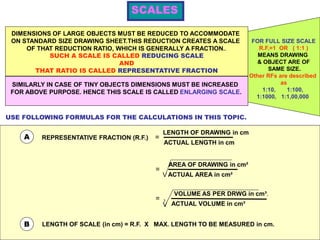
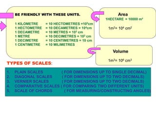
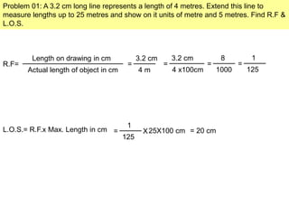

The document discusses different types of scales and their applications in measuring dimensions, including reducing and enlarging scales, as well as specific scale constructions such as plain, diagonal, vernier, comparative, and scale of chords. It provides formulas for calculating representative fractions and outlines practical problems with step-by-step solutions to construct scales for measuring lengths, areas, and angles. The text emphasizes the importance of accurate scaling for large and small objects to fit standard drawing sheets.