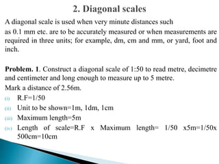
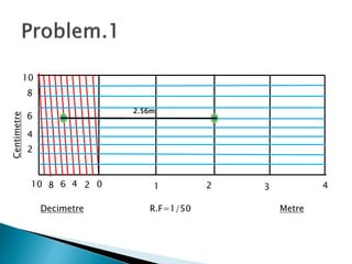
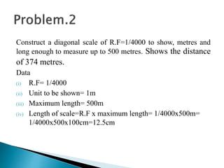
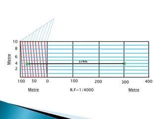
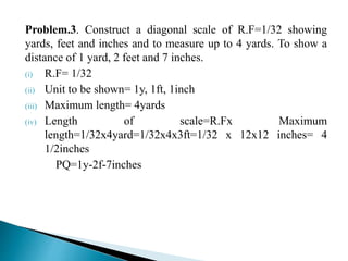
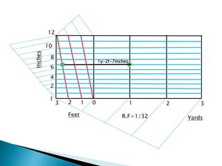
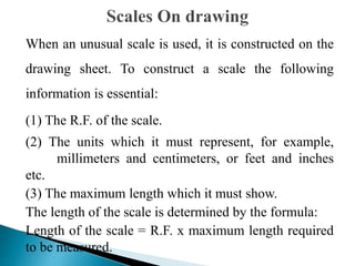
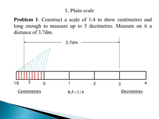
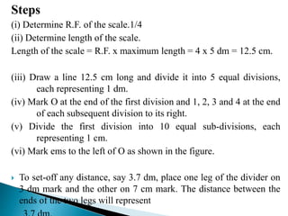
ENGINEERING DRAWING
Credit hours: 2+1
Contact hours: 28+42
A diagonal scale is used when very minute distances such
as 0.1 mm etc. are to be accurately measured or when measurements are
required in three units; for example, dm, cm and mm, or yard, foot and
inch.
Problem. 1. Construct a diagonal scale of 1:50 to read metre, decimetre
and centimeter and long enough to measure up to 5 metre.
Mark a distance of 2.56m.
(i) R.F=1/50
(ii) Unit to be shown=1m, 1dm, 1cm
(iii) Maximum length=5m
(iv) Length of scale=R.F x Maximum length= 1/50 x5m=1/50x
500cm=10cm
0 1 2 3 4
Metre
Decimetre
10 6
R.F=1/50
2.56m
2
8 4
10
8
6
4
2
Centimetre
Construct a diagonal scale of R.F=1/4000 to show, metres and
long enough to measure up to 500 metres. Shows the distance
of 374 metres.
Data
(i) R.F= 1/4000
(ii) Unit to be shown= 1m
(iii) Maximum length= 500m
(iv) Length of scale=R.F x maximum length= 1/4000x500m=
1/4000x500x100cm=12.5cm
0 100 200 300 400
Metre
Metre
100
R.F=1/4000
374m
50
10
8
6
4
2
Metre
Problem.3. Construct a diagonal scale of R.F=1/32 showing
yards, feet and inches and to measure up to 4 yards. To show a
distance of 1 yard, 2 feet and 7 inches.
(i) R.F= 1/32
(ii) Unit to be shown= 1y, 1ft, 1inch
(iii) Maximum length= 4yards
(iv) Length of scale=R.Fx Maximum
length=1/32x4yard=1/32x4x3ft=1/32 x 12x12 inches= 4
1/2inches
PQ=1y-2f-7inches
0 1 2 3
Yards
Feet
3 2
R.F=1/32
1y-2f-7inches
1
10
8
6
4
2
Inches
12
1
Construct a diagonal scale of 3: 200 i.e. 1:66 2/3
showing metres, decimetres and centimetres and to
measure up to 6 metres.
When drawings are drawn smaller than the actual size
of the objects (as in case of buildings, bridges, large
machines etc.) the scale used is said to be a reducing
scale (1 : 5). Drawings of small machine parts,
mathematical instruments, watches etc. are made larger
than their real size. These are said to be drawn on an
enlarging scale (5 : 1 ).
The scales can be expressed in the following three ways:
(1) Engineer’s scale: In this case, the relation between the
dimension on the drawing and the actual dimension of the
object is mentioned numerically in the style as 10 mm = 5 m
etc.
2) Graphical scale: The scale is drawn on the drawing itself.
As the drawing becomes old, the engineer's scale may shrink
and may not give accurate results.
However, such is not the case with graphical scale because if
the drawing shrinks, the scale will also shrink. Hence, the
graphical scale.is commonly used in survey maps.
(3) Representative fraction: The ratio of the length of
the object represented on drawing to the actual length
of the object represented is called the Representative
Fraction (i.e. R.F.).
R.F. = Length of the drawing/Actual length of object
When a 1 cm long line in a drawing represents 1 metre
length of the object, the
R.F. is equal to 1cm/1m = 1cm/1x100cm=1/100
and the scale of the drawing will be
1 : 100 or 1/100 full size.
The R.F. of a drawing is greater than unity when it is
drawn on an enlarging scale. For example, when a 2 mm
long edge of an object is shown in a drawing by a line
1cm long, the R F is 1 cm/2mm=10mm/2mm= 10/2= 5
such a drawing is said to be drawn on scale 5 : 1 or five
times full-size.
The scales used in practice are classified as under:
(1) Plain scales (4) Vernier scales
(2) Diagonal scales (5) Scale of chords.
(3) Comparative scales
When an unusual scale is used, it is constructed on the
drawing sheet. To construct a scale the following
information is essential:
(1) The R.F. of the scale.
(2) The units which it must represent, for example,
millimeters and centimeters, or feet and inches
etc.
(3) The maximum length which it must show.
The length of the scale is determined by the formula:
Length of the scale = R.F. x maximum length required
to be measured.
In every scale,
(i) The zero should be placed at the end of the first main
division, i.e. between the unit and its sub-divisions.
(ii) From the zero mark, the units should be numbered to
the right and its sub-divisions to the left
(iii) The names of the units and the sub-divisions
should be stated clearly below or at the
respective ends.
(iv) The name of the scale (e.g. scale, 1 : 10) or its R.F.
should be mentioned below the scale.
 A plain scale consists of a line divided into suitable number of
equal parts or units, the first of which is sub-divided into
smaller parts. Plain scales represent either two units or a unit
and its sub-division
Problem 1. Construct a scale of 1:4 to show centimetres and
long enough to measure up to 5 decimetres. Measure on it a
distance of 3.7dm.
0 1 2 3 4
Decimetres
Centimetres
10 5
R.F=1/4
3.7dm
Steps
(i) Determine R.F. of the scale.1/4
(ii) Determine length of the scale.
Length of the scale = R.F. x maximum length = 4 x 5 dm = 12.5 cm.
(iii) Draw a line 12.5 cm long and divide it into 5 equal divisions,
each representing 1 dm.
(iv) Mark O at the end of the first division and 1, 2, 3 and 4 at the end
of each subsequent division to its right.
(v) Divide the first division into 10 equal sub-divisions, each
representing 1 cm.
(vi) Mark ems to the left of O as shown in the figure.
 To set-off any distance, say 3.7 dm, place one leg of the divider on
3 dm mark and the other on 7 cm mark. The distance between the
ends of the two legs will represent

ED-Lecture-8.pptx

  • 1.
    ENGINEERING DRAWING Credit hours:2+1 Contact hours: 28+42
  • 2.
    A diagonal scaleis used when very minute distances such as 0.1 mm etc. are to be accurately measured or when measurements are required in three units; for example, dm, cm and mm, or yard, foot and inch. Problem. 1. Construct a diagonal scale of 1:50 to read metre, decimetre and centimeter and long enough to measure up to 5 metre. Mark a distance of 2.56m. (i) R.F=1/50 (ii) Unit to be shown=1m, 1dm, 1cm (iii) Maximum length=5m (iv) Length of scale=R.F x Maximum length= 1/50 x5m=1/50x 500cm=10cm
  • 3.
    0 1 23 4 Metre Decimetre 10 6 R.F=1/50 2.56m 2 8 4 10 8 6 4 2 Centimetre
  • 4.
    Construct a diagonalscale of R.F=1/4000 to show, metres and long enough to measure up to 500 metres. Shows the distance of 374 metres. Data (i) R.F= 1/4000 (ii) Unit to be shown= 1m (iii) Maximum length= 500m (iv) Length of scale=R.F x maximum length= 1/4000x500m= 1/4000x500x100cm=12.5cm
  • 5.
    0 100 200300 400 Metre Metre 100 R.F=1/4000 374m 50 10 8 6 4 2 Metre
  • 6.
    Problem.3. Construct adiagonal scale of R.F=1/32 showing yards, feet and inches and to measure up to 4 yards. To show a distance of 1 yard, 2 feet and 7 inches. (i) R.F= 1/32 (ii) Unit to be shown= 1y, 1ft, 1inch (iii) Maximum length= 4yards (iv) Length of scale=R.Fx Maximum length=1/32x4yard=1/32x4x3ft=1/32 x 12x12 inches= 4 1/2inches PQ=1y-2f-7inches
  • 7.
    0 1 23 Yards Feet 3 2 R.F=1/32 1y-2f-7inches 1 10 8 6 4 2 Inches 12 1
  • 8.
    Construct a diagonalscale of 3: 200 i.e. 1:66 2/3 showing metres, decimetres and centimetres and to measure up to 6 metres.
  • 9.
    When drawings aredrawn smaller than the actual size of the objects (as in case of buildings, bridges, large machines etc.) the scale used is said to be a reducing scale (1 : 5). Drawings of small machine parts, mathematical instruments, watches etc. are made larger than their real size. These are said to be drawn on an enlarging scale (5 : 1 ).
  • 10.
    The scales canbe expressed in the following three ways: (1) Engineer’s scale: In this case, the relation between the dimension on the drawing and the actual dimension of the object is mentioned numerically in the style as 10 mm = 5 m etc. 2) Graphical scale: The scale is drawn on the drawing itself. As the drawing becomes old, the engineer's scale may shrink and may not give accurate results. However, such is not the case with graphical scale because if the drawing shrinks, the scale will also shrink. Hence, the graphical scale.is commonly used in survey maps.
  • 11.
    (3) Representative fraction:The ratio of the length of the object represented on drawing to the actual length of the object represented is called the Representative Fraction (i.e. R.F.). R.F. = Length of the drawing/Actual length of object When a 1 cm long line in a drawing represents 1 metre length of the object, the R.F. is equal to 1cm/1m = 1cm/1x100cm=1/100 and the scale of the drawing will be 1 : 100 or 1/100 full size.
  • 12.
    The R.F. ofa drawing is greater than unity when it is drawn on an enlarging scale. For example, when a 2 mm long edge of an object is shown in a drawing by a line 1cm long, the R F is 1 cm/2mm=10mm/2mm= 10/2= 5 such a drawing is said to be drawn on scale 5 : 1 or five times full-size.
  • 13.
    The scales usedin practice are classified as under: (1) Plain scales (4) Vernier scales (2) Diagonal scales (5) Scale of chords. (3) Comparative scales
  • 14.
    When an unusualscale is used, it is constructed on the drawing sheet. To construct a scale the following information is essential: (1) The R.F. of the scale. (2) The units which it must represent, for example, millimeters and centimeters, or feet and inches etc. (3) The maximum length which it must show. The length of the scale is determined by the formula: Length of the scale = R.F. x maximum length required to be measured.
  • 15.
    In every scale, (i)The zero should be placed at the end of the first main division, i.e. between the unit and its sub-divisions. (ii) From the zero mark, the units should be numbered to the right and its sub-divisions to the left (iii) The names of the units and the sub-divisions should be stated clearly below or at the respective ends. (iv) The name of the scale (e.g. scale, 1 : 10) or its R.F. should be mentioned below the scale.
  • 16.
     A plainscale consists of a line divided into suitable number of equal parts or units, the first of which is sub-divided into smaller parts. Plain scales represent either two units or a unit and its sub-division
  • 17.
    Problem 1. Constructa scale of 1:4 to show centimetres and long enough to measure up to 5 decimetres. Measure on it a distance of 3.7dm. 0 1 2 3 4 Decimetres Centimetres 10 5 R.F=1/4 3.7dm
  • 18.
    Steps (i) Determine R.F.of the scale.1/4 (ii) Determine length of the scale. Length of the scale = R.F. x maximum length = 4 x 5 dm = 12.5 cm. (iii) Draw a line 12.5 cm long and divide it into 5 equal divisions, each representing 1 dm. (iv) Mark O at the end of the first division and 1, 2, 3 and 4 at the end of each subsequent division to its right. (v) Divide the first division into 10 equal sub-divisions, each representing 1 cm. (vi) Mark ems to the left of O as shown in the figure.  To set-off any distance, say 3.7 dm, place one leg of the divider on 3 dm mark and the other on 7 cm mark. The distance between the ends of the two legs will represent