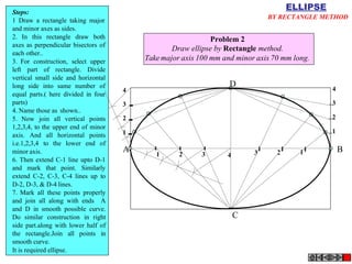
This document provides information about engineering drawing scales. It discusses various types of scales including plain scales, diagonal scales, and Vernier scales. Examples are given for how to construct and use each type of scale. Plain scales can measure two units or a unit and subdivision, diagonal scales provide three successive dimensions, and Vernier scales allow for very accurate measurements of small units. Formulas are provided for calculating representative factors and scale lengths for different problems.


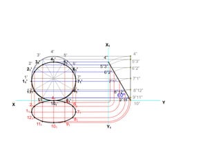
![Problem No.10: Point P is 40 mm and 30 mm from horizontal
and vertical axes respectively.Draw Hyperbola through it.
Solution Steps:
1) Extend horizontal
HYPERBOLA
THROUGH A POINT OF
KNOWN CO-ORDINATES
line from P to right side.
2) Extend vertical line
from P upward.
3) On horizontal line
from P, mark some points
taking any distance and
name them after P-1,
2,3,4 etc.
4) Join 1-2-3-4 points
to pole O. Let them cut
part [P-B] also at 1,2,3,4
points.
5) From horizontal
1,2,3,4 draw vertical
lines downwards and
6) From vertical 1,2,3,4
points [from P-B] draw
horizontal lines.
2
1
2 1 P
1
1 2 3
7) Line from 1
horizontal and line from
1 vertical will meet at
40 mm 2
3
P1.Similarly mark P2, P3,
P4 points.
8) Repeat the procedure
by marking four points
on upward vertical line
from P and joining all
those to pole O. Name
this points P6, P7, P8 etc.
and join them by smooth
curve.
O
30 mm](https://image.slidesharecdn.com/edppt0-230510175122-174c3a8a/85/ED-PPT_0-pdf-30-320.jpg)


![Engineering-Drawing-Part-1[1].ppt](https://cdn.slidesharecdn.com/ss_thumbnails/engineering-drawing-part-11-230102162430-dbca7f35-thumbnail.jpg?width=640&height=640&fit=bounds)


