Downloaded 110 times
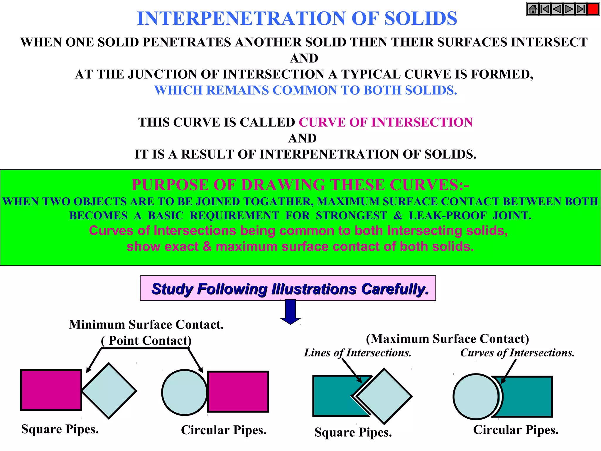
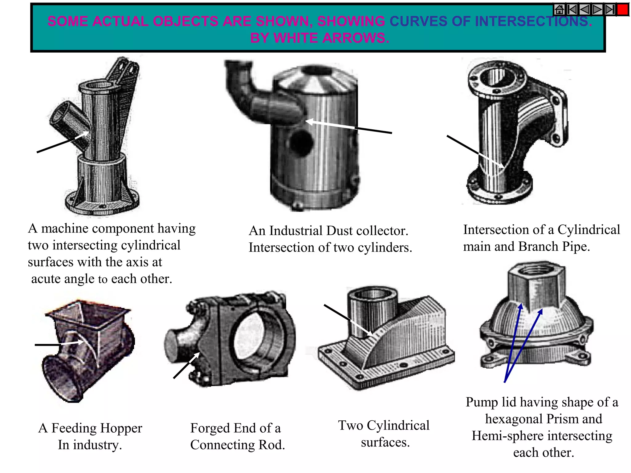
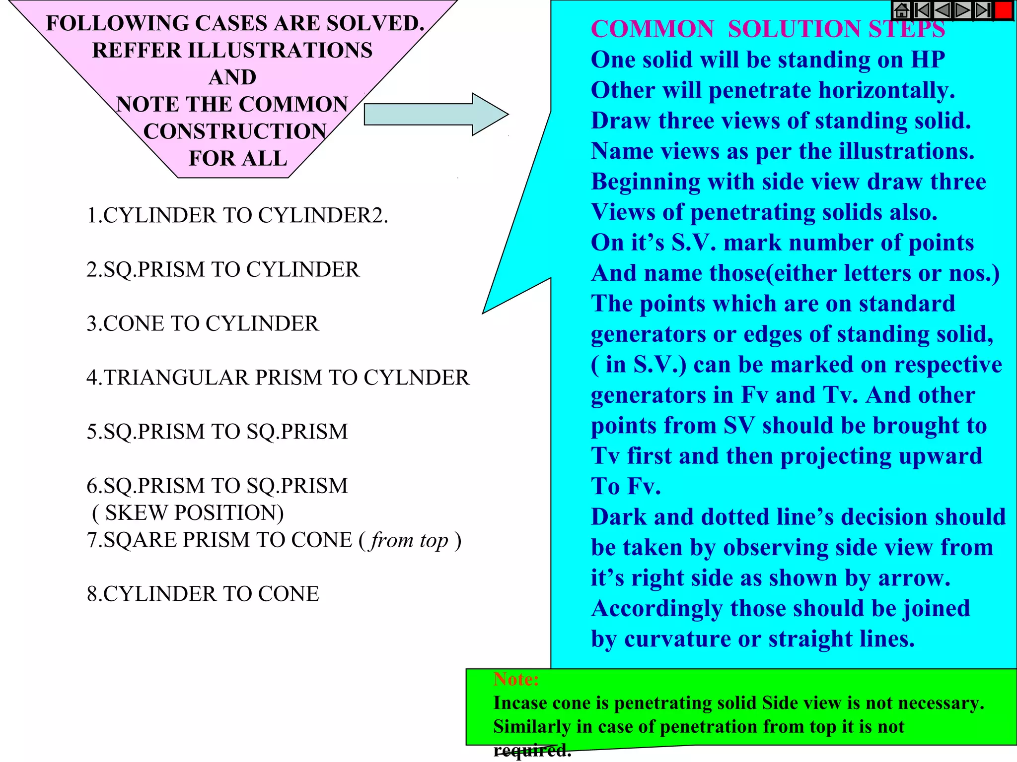
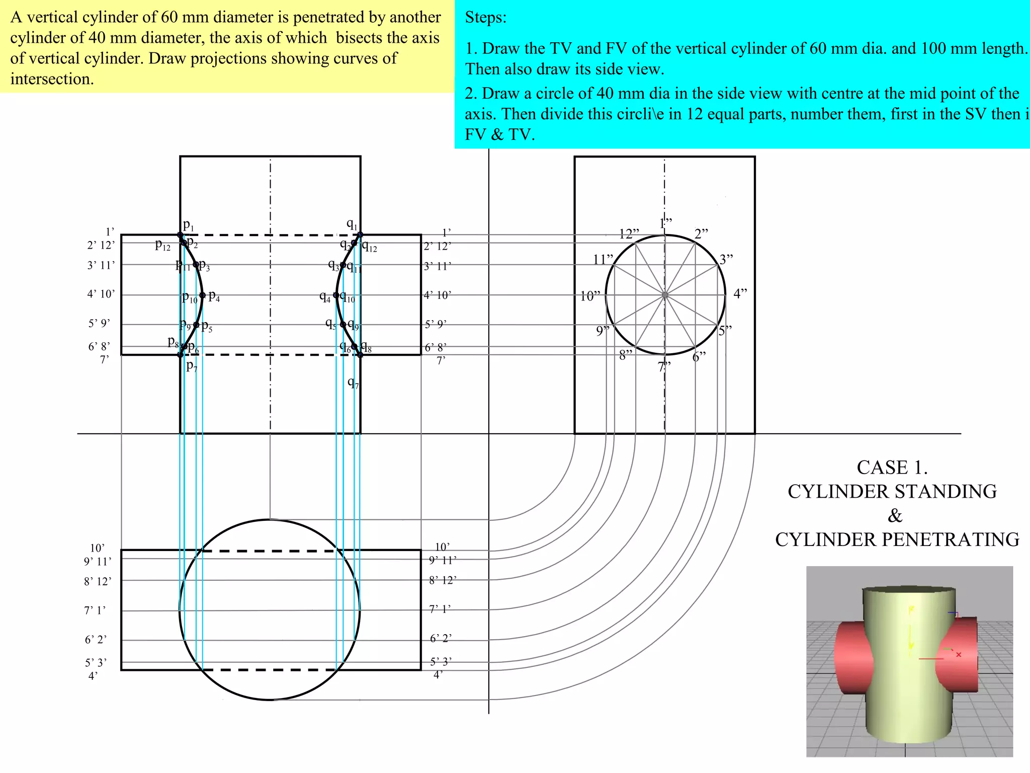
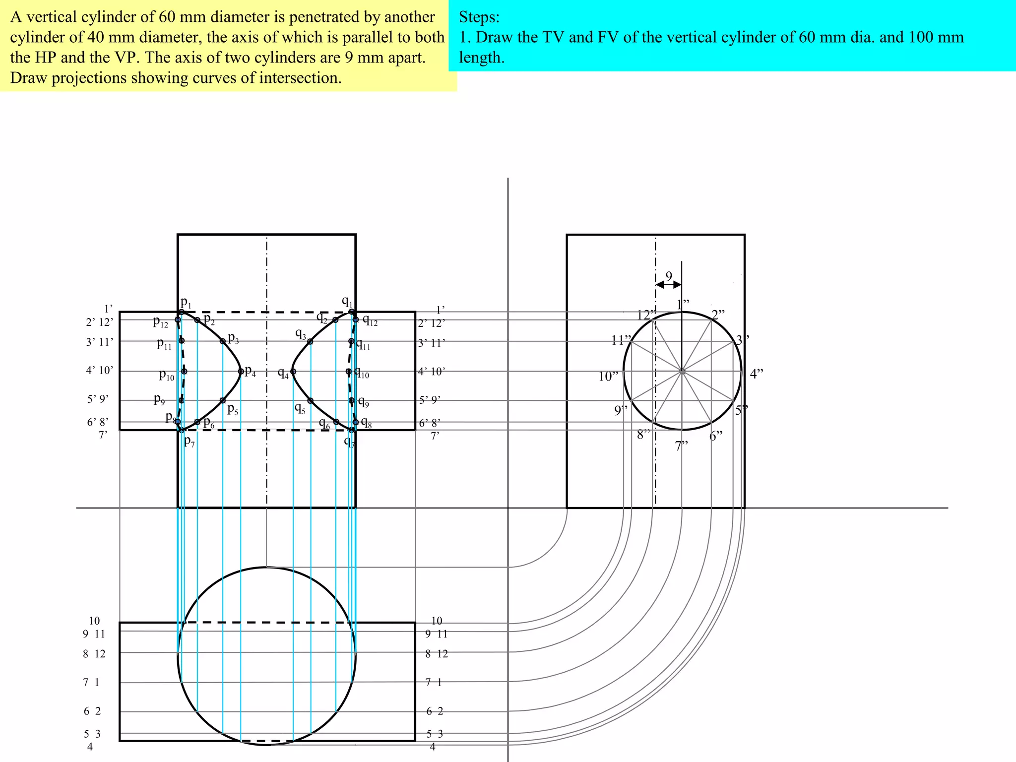
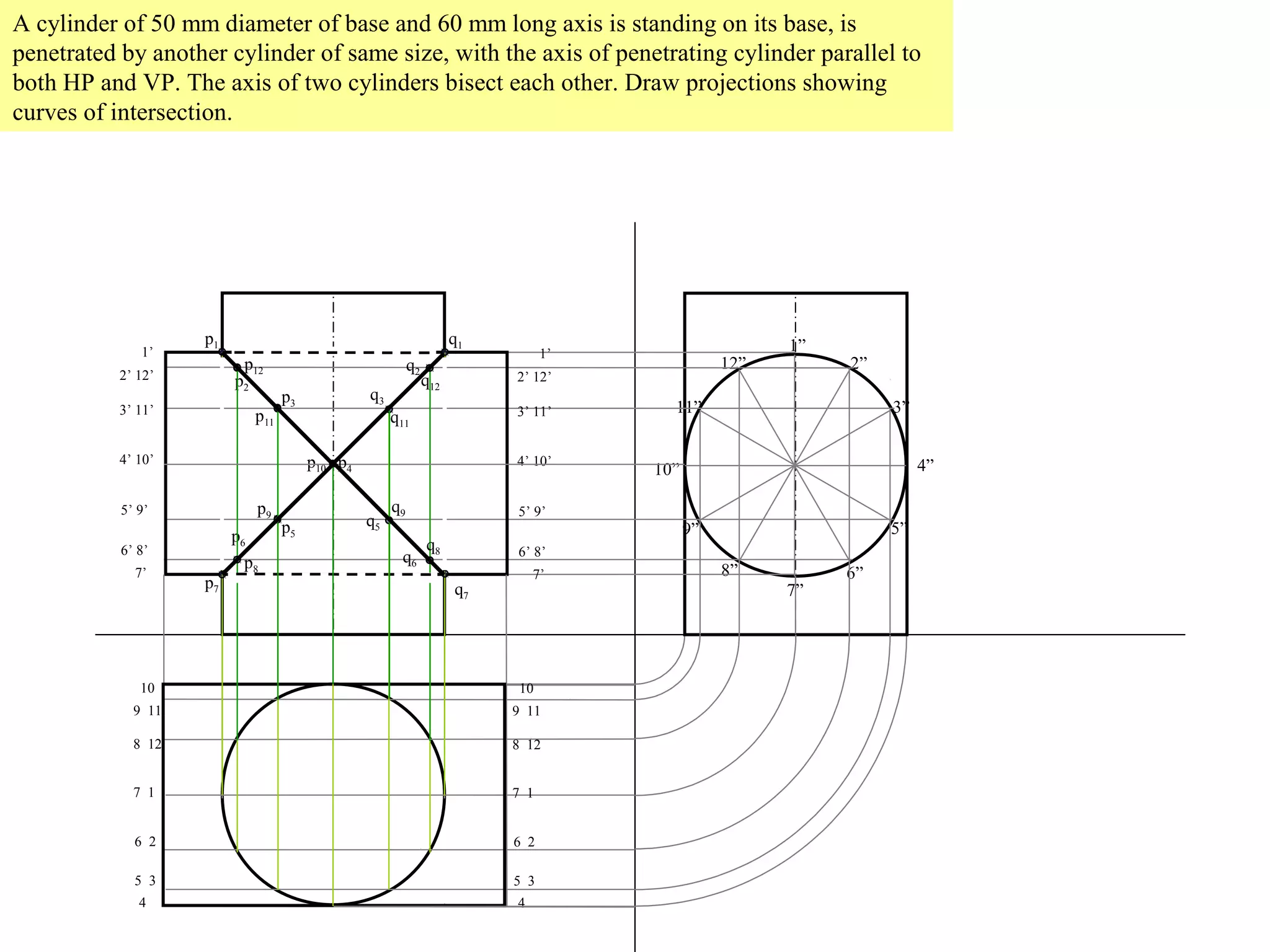
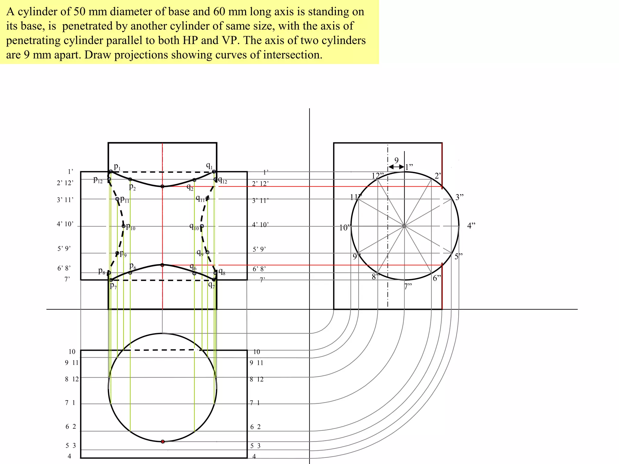
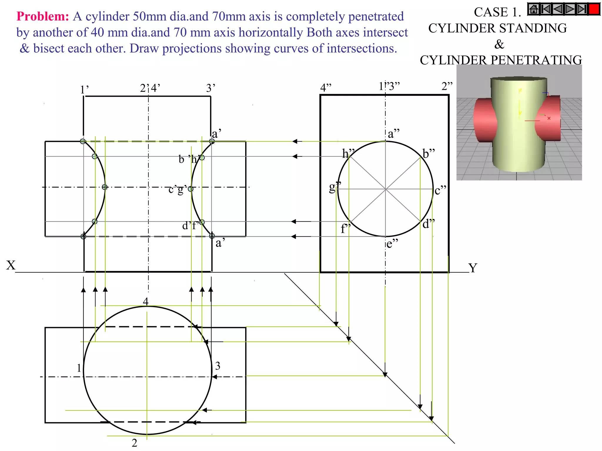
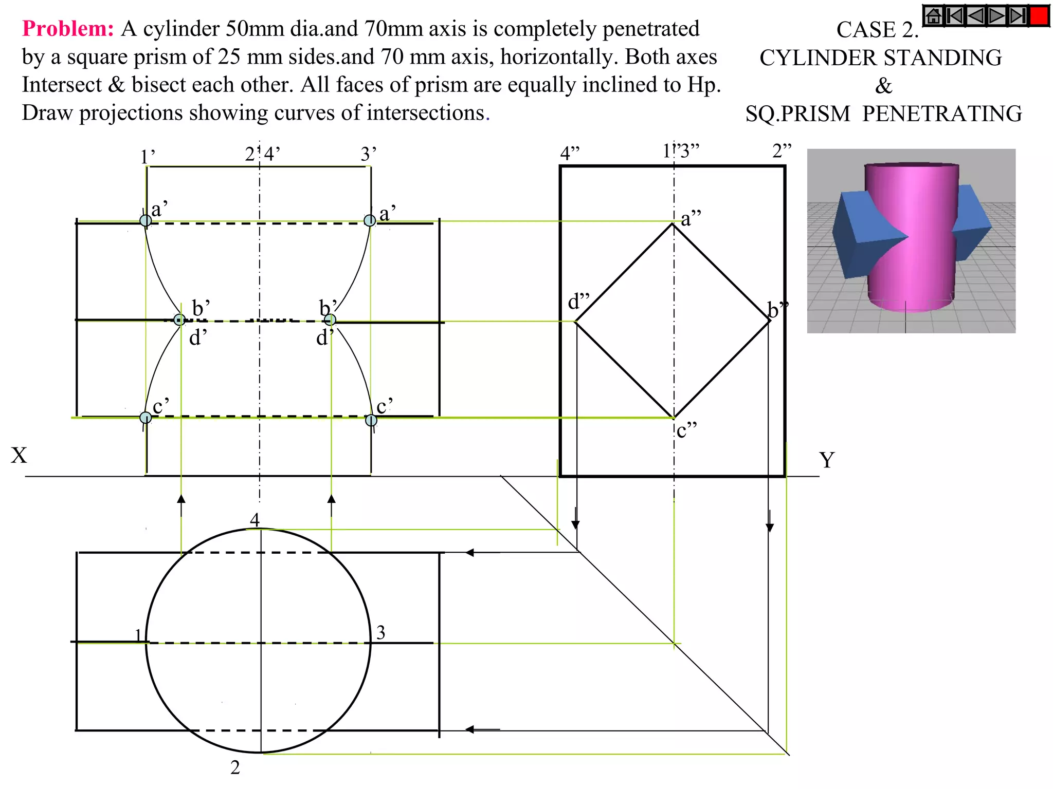
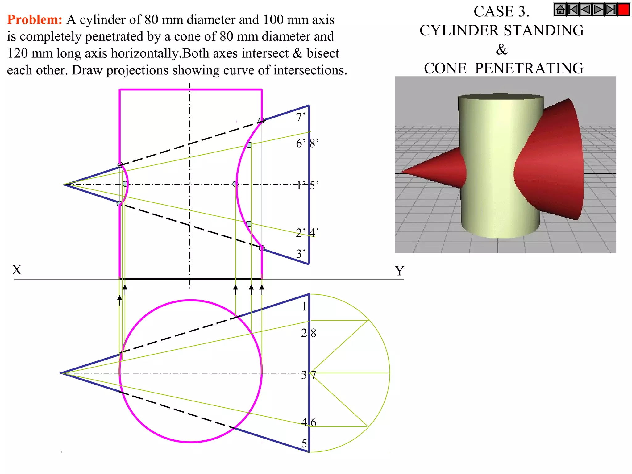
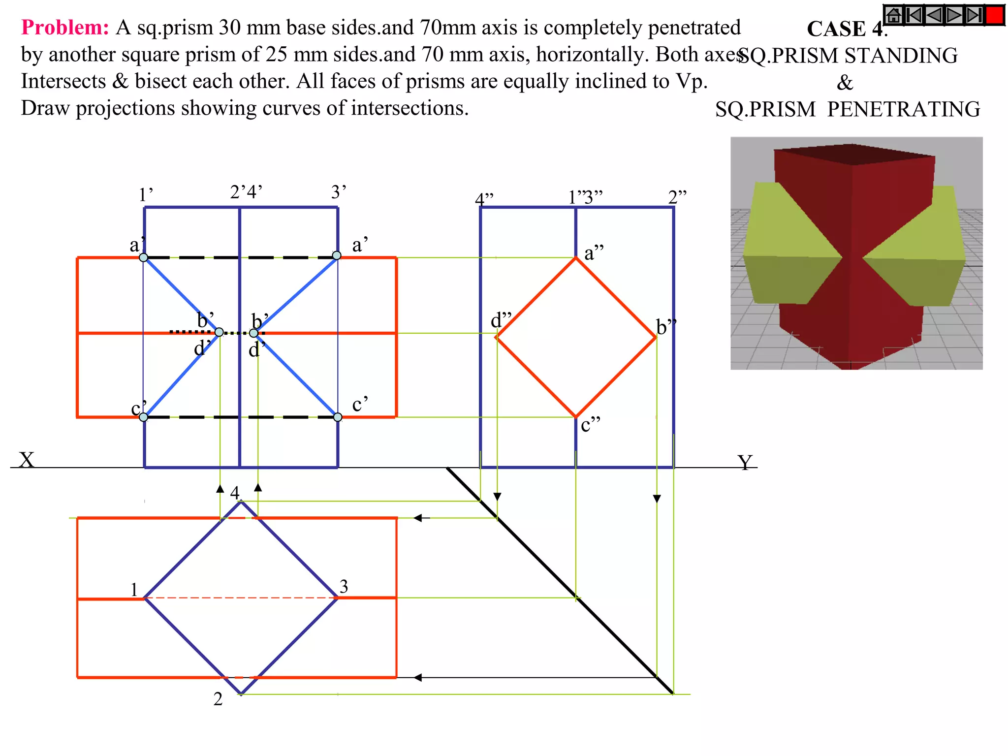
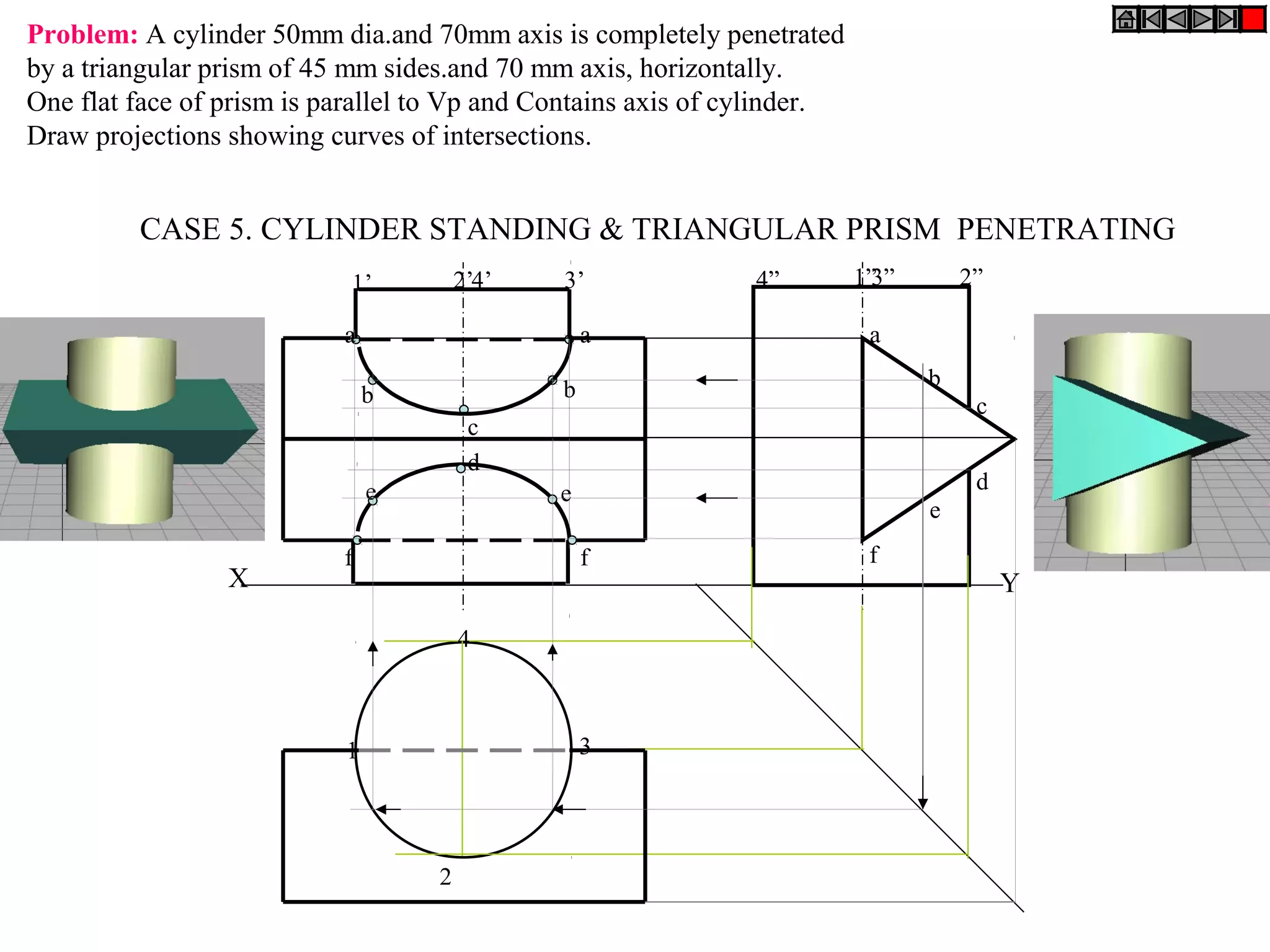
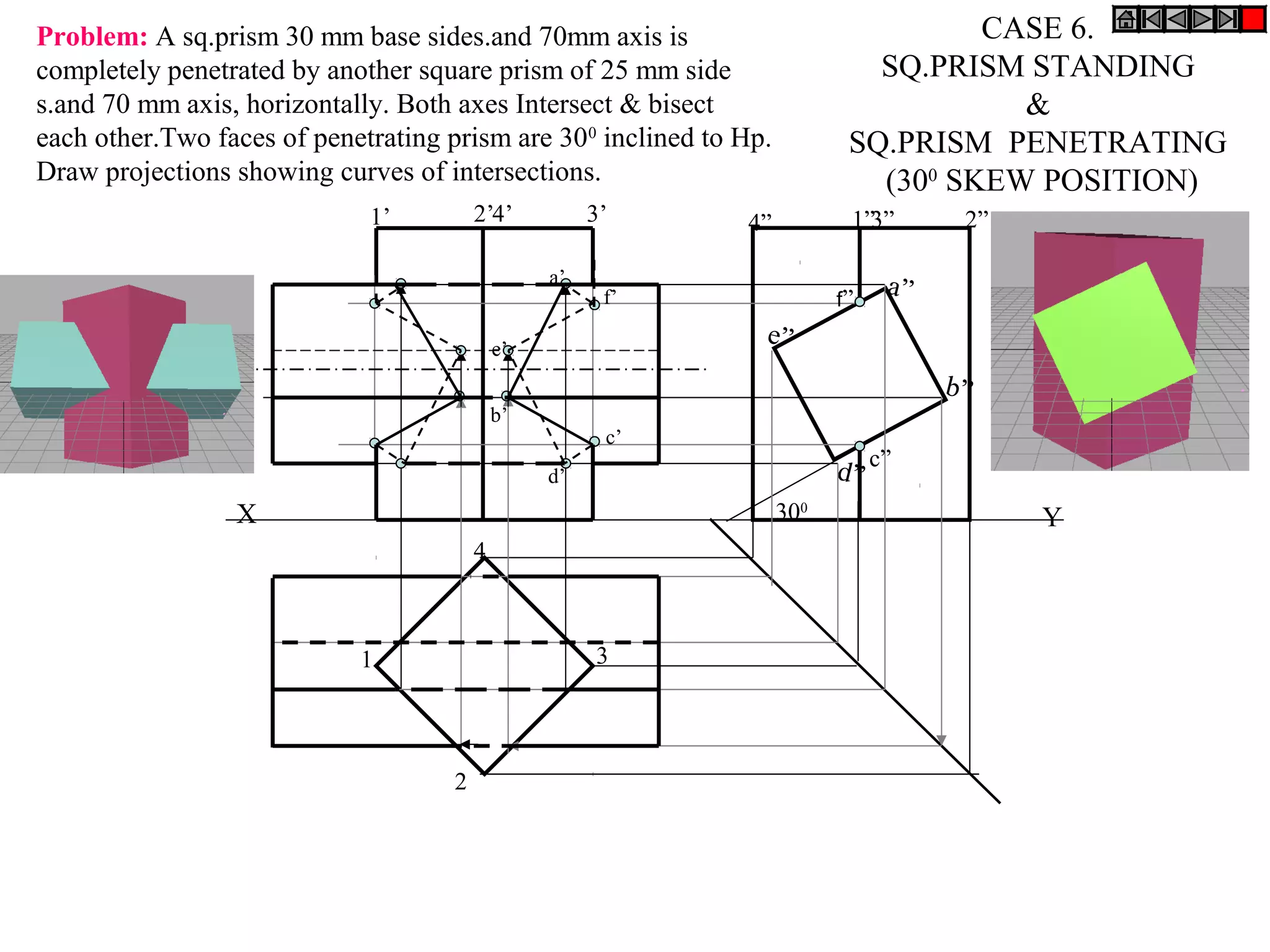
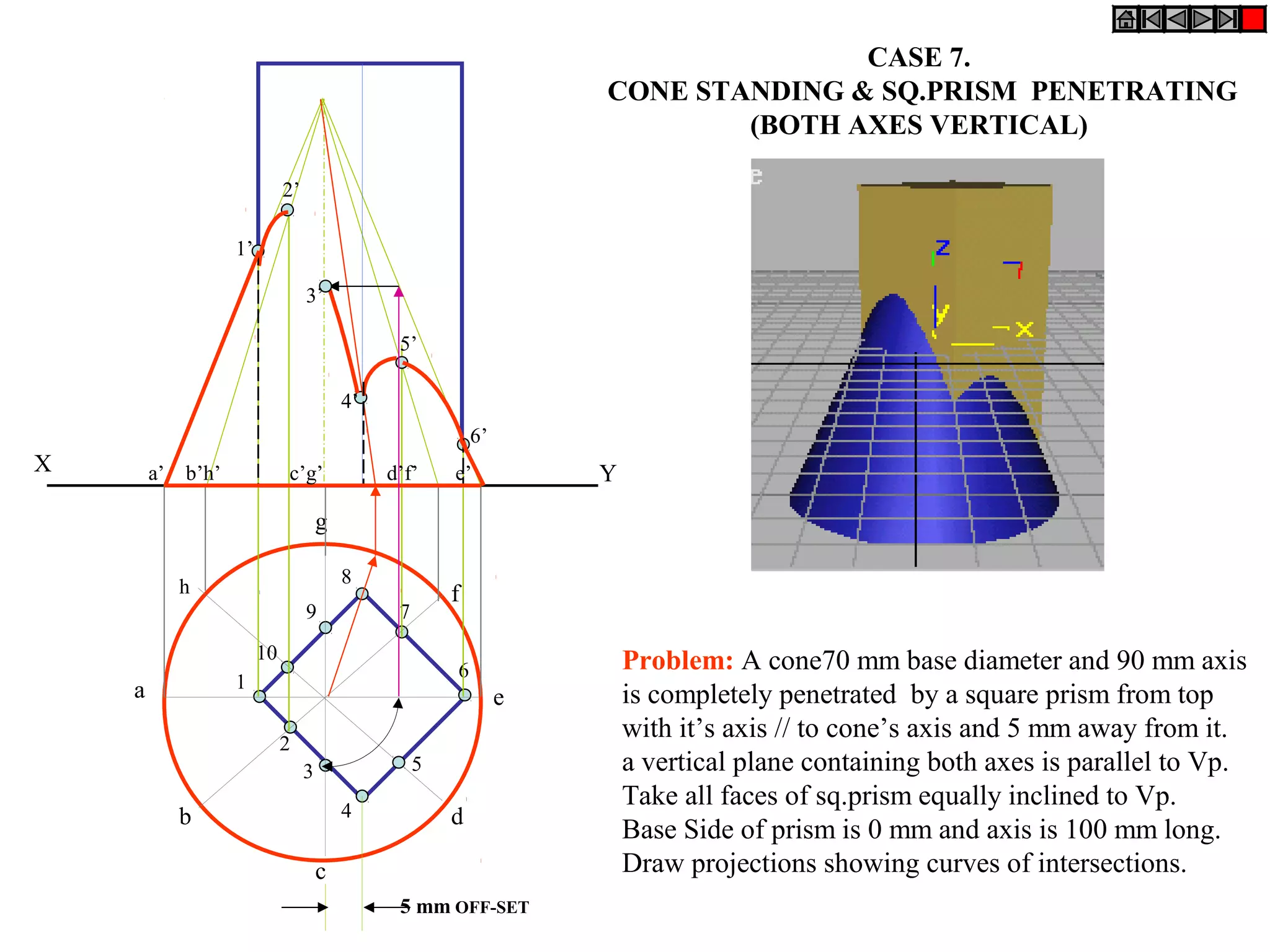

The document discusses the interpenetration of solids, specifically focusing on the curves of intersection that form when two solids penetrate each other. It highlights the importance of these curves for ensuring maximum contact surface and strong, leak-proof joints in engineering applications. Detailed methods and examples are provided for drawing projections to illustrate these intersections for various shapes including cylindrical and prismatic forms.