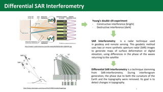
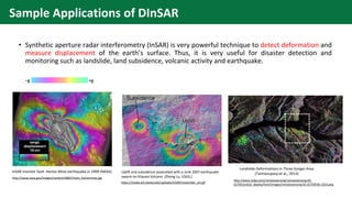
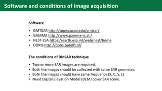
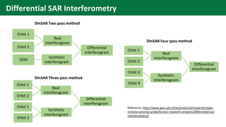
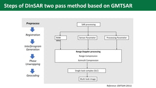
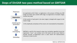
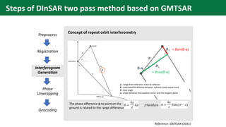
Center for Research and Application for Satellite Remote Sensing
Yamaguchi University
SAR Interferometry Technique
Preprocess Registration
Interferometry
analysis
Geocoding
2
Young’s double slit experiment
- Constructive interference (bright)
- Destructive interference (dark)
SAR Interferometry is a radar technique used
in geodesy and remote sensing. This geodetic method
uses two or more synthetic aperture radar (SAR) images
to generate maps of surface deformation or digital
elevation, using differences in the phase of the waves
returning to the satellite
Differential SAR Interferometry is a technique stemming
from SAR-Interferometry. During interferogram
generation, the phase due to both the curvature of the
Earth and the topography were removed. Its goal is to
detect changes in topography.
http://media-2.web.britannica.com/eb-media/96/96596-004-1D8E9F0F.jpg
http://www.intechopen.com/source/html/10381/media/image8.jpg
Differential SAR Interferometry
Sample Applications of DInSAR
• Synthetic aperture radar interferometry (InSAR) is very powerful technique to detect deformation and
measure displacement of the earth’s surface. Thus, it is very useful for disaster detection and
monitoring such as landslide, land subsidence, volcanic activity and earthquake.
Uplift and subsidence associated with a June 2007 earthquake
swarm on Kilauea Volcano (Zhong Lu, USGS,)
InSAR monitor fault Hector Mine earthquake in 1999 (NASA)
Landslide Deformations in Three Gorges Area
(Tantianuparp et al., 2013)
http://www.nasa.gov/images/content/48847main_hectormine.jpg
http://www.mdpi.com/remotesensing/remotesensing-05-
02704/article_deploy/html/images/remotesensing-05-02704f3b-1024.png
https://media.asf.alaska.edu/uploads/InSAR/november_sm.gif
Software and conditions of image acquisition
The conditions of DInSAR technique
▪ Two or more SAR images are required.
▪ Both the images should be collected with same SAR geometry.
▪ Both the images should have same frequency (X, C, S, L)
▪ Need Digital Elevation Model (DEM) cover SAR scene.
Software
▪ GMTSAR http://topex.ucsd.edu/gmtsar/
▪ GAMMA http://www.gamma-rs.ch/
▪ NEST ESA https://earth.esa.int/web/nest/home
▪ DORIS http://doris.tudelft.nl/
Differential SAR Interferometry
DInSAR Two pass method
DInSAR Three pass method
DInSAR Four pass method
Reference: http://www.geo.uzh.ch/en/units/rsl/research/radar-
remote-sensing-sarlab/former-research-projects/differential-sar-
interferometry/
Differential
Interferogram
Real
Interferogram
Orbit 1
Orbit 2
Synthetic
Interferogram
DEM
Differential
Interferogram
Real
Interferogram
Orbit 1
Orbit 2
Synthetic
Interferogram
Orbit 1
Orbit 3
Differential
Interferogram
Real
Interferogram
Orbit 1
Orbit 2
Synthetic
Interferogram
Orbit 3
Orbit 4
Steps of DInSAR two pass method based on GMTSAR
Preprocess
Registration
Interferogram
Generation
Phase
Unwrapping
Geocoding
Range Doppler processing
Range Compression
Azimuth Compression
Single look complex (SLC)
Multi look image
SAR processing
RAW
data
Sensor Parameter Processing Parameter
Reference: GMTSAR (2011)
Steps of DInSAR two pass method based on GMTSAR
Preprocess
Registration
Interferogram
Generation
Phase
Unwrapping
Geocoding
Co-registration of SLC Data: co-registration is the process of fitting one SAR
image accurately upon another SAR image. Co-registration of complex images
involves two steps.
1) the location of each pixel in the slave image is changed with respect to the
master image.
2) the amplitudes and phases of the sensors are recalculated by interpolation.
GMTSAR is used for this research using cross correlation algorithm (xcorr) for
registration. “xcorr” uses window size of 64 pixels and has never failed to
provide accurate co-registration even in cases where the interferometric
coherence is close to zero.
Reference: GMTSAR (2011)
Preprocess
Registration
Interferogram
Generation
Phase
Unwrapping
Geocoding
Concept of repeat orbit interferometry
The phase difference φ to point on the
ground is related to the range difference
;Therefore
ρ - range from reference track to reflector
B - total baseline distance between reference and repeat track
θ - look angle
α - angle between the baseline vector and the tangent plane
= Bcos(θ-α)
= Bsin(θ-α)
θ-α
Reference: GMTSAR (2011)
Steps of DInSAR two pass method based on GMTSAR
Preprocess
Registration
Interferogram
Generation
Phase
Unwrapping
Geocoding
Correction of earth curvature and topographic phase
Interpolate the topography
For other information, it can be computed from SAR data
b(a) - radius of the spacecraft orbit for the
reference image
B(a) - the length of the baseline
α(a) - the orientation of the baseline
topography (range, azimuth)
Reference: GMTSAR (2011)
Steps of DInSAR two pass method based on GMTSAR
Preprocess
Registration
Interferogram
Generation
Phase
Unwrapping
Geocoding
Phase due to earth curvature and topography
Law of cosine
It can be rewritten as
Phase to range =
So, Phase difference = φ1- φ2
Reference: GMTSAR (2011)
δρ = -B sin (θ-α)
Steps of DInSAR two pass method based on GMTSAR
Preprocess
Registration
Interferogram
Generation
Phase
Unwrapping
Geocoding
Phase unwrapping: The interferometric phase shows many discontinuities,
which originate the classical fringe pattern. The interferometric phase is
almost linearly proportional to the topographic height. The difficulty is that
the interferometric phase is only known to module 360 degrees. If the phase
variation exceeds 360 degrees, it wraps around to 0 degrees. It is necessary
to unwrap the phase in the interferogram by using several algorithms for
converting the interferometric phase to topographic phase.
Steps of DInSAR two pass method based on GMTSAR
Preprocess
Registration
Interferogram
Generation
Phase
Unwrapping
Geocoding
The final step is to geocode all the products by transforming from
the range/azimuth coordinate system of the master image to
longitude and latitude.
Geocode
Amplitude image
Interferogram image
Sample image from http://topex.ucsd.edu/gmtsar/downloads/
Steps of DInSAR two pass method based on GMTSAR

SAR Interferometry Technique

  • 1.
    Center for Researchand Application for Satellite Remote Sensing Yamaguchi University SAR Interferometry Technique Preprocess Registration Interferometry analysis Geocoding
  • 2.
    2 Young’s double slitexperiment - Constructive interference (bright) - Destructive interference (dark) SAR Interferometry is a radar technique used in geodesy and remote sensing. This geodetic method uses two or more synthetic aperture radar (SAR) images to generate maps of surface deformation or digital elevation, using differences in the phase of the waves returning to the satellite Differential SAR Interferometry is a technique stemming from SAR-Interferometry. During interferogram generation, the phase due to both the curvature of the Earth and the topography were removed. Its goal is to detect changes in topography. http://media-2.web.britannica.com/eb-media/96/96596-004-1D8E9F0F.jpg http://www.intechopen.com/source/html/10381/media/image8.jpg Differential SAR Interferometry
  • 3.
    Sample Applications ofDInSAR • Synthetic aperture radar interferometry (InSAR) is very powerful technique to detect deformation and measure displacement of the earth’s surface. Thus, it is very useful for disaster detection and monitoring such as landslide, land subsidence, volcanic activity and earthquake. Uplift and subsidence associated with a June 2007 earthquake swarm on Kilauea Volcano (Zhong Lu, USGS,) InSAR monitor fault Hector Mine earthquake in 1999 (NASA) Landslide Deformations in Three Gorges Area (Tantianuparp et al., 2013) http://www.nasa.gov/images/content/48847main_hectormine.jpg http://www.mdpi.com/remotesensing/remotesensing-05- 02704/article_deploy/html/images/remotesensing-05-02704f3b-1024.png https://media.asf.alaska.edu/uploads/InSAR/november_sm.gif
  • 4.
    Software and conditionsof image acquisition The conditions of DInSAR technique ▪ Two or more SAR images are required. ▪ Both the images should be collected with same SAR geometry. ▪ Both the images should have same frequency (X, C, S, L) ▪ Need Digital Elevation Model (DEM) cover SAR scene. Software ▪ GMTSAR http://topex.ucsd.edu/gmtsar/ ▪ GAMMA http://www.gamma-rs.ch/ ▪ NEST ESA https://earth.esa.int/web/nest/home ▪ DORIS http://doris.tudelft.nl/
  • 5.
    Differential SAR Interferometry DInSARTwo pass method DInSAR Three pass method DInSAR Four pass method Reference: http://www.geo.uzh.ch/en/units/rsl/research/radar- remote-sensing-sarlab/former-research-projects/differential-sar- interferometry/ Differential Interferogram Real Interferogram Orbit 1 Orbit 2 Synthetic Interferogram DEM Differential Interferogram Real Interferogram Orbit 1 Orbit 2 Synthetic Interferogram Orbit 1 Orbit 3 Differential Interferogram Real Interferogram Orbit 1 Orbit 2 Synthetic Interferogram Orbit 3 Orbit 4
  • 6.
    Steps of DInSARtwo pass method based on GMTSAR Preprocess Registration Interferogram Generation Phase Unwrapping Geocoding Range Doppler processing Range Compression Azimuth Compression Single look complex (SLC) Multi look image SAR processing RAW data Sensor Parameter Processing Parameter Reference: GMTSAR (2011)
  • 7.
    Steps of DInSARtwo pass method based on GMTSAR Preprocess Registration Interferogram Generation Phase Unwrapping Geocoding Co-registration of SLC Data: co-registration is the process of fitting one SAR image accurately upon another SAR image. Co-registration of complex images involves two steps. 1) the location of each pixel in the slave image is changed with respect to the master image. 2) the amplitudes and phases of the sensors are recalculated by interpolation. GMTSAR is used for this research using cross correlation algorithm (xcorr) for registration. “xcorr” uses window size of 64 pixels and has never failed to provide accurate co-registration even in cases where the interferometric coherence is close to zero. Reference: GMTSAR (2011)
  • 8.
    Preprocess Registration Interferogram Generation Phase Unwrapping Geocoding Concept of repeatorbit interferometry The phase difference φ to point on the ground is related to the range difference ;Therefore ρ - range from reference track to reflector B - total baseline distance between reference and repeat track θ - look angle α - angle between the baseline vector and the tangent plane = Bcos(θ-α) = Bsin(θ-α) θ-α Reference: GMTSAR (2011) Steps of DInSAR two pass method based on GMTSAR
  • 9.
    Preprocess Registration Interferogram Generation Phase Unwrapping Geocoding Correction of earthcurvature and topographic phase Interpolate the topography For other information, it can be computed from SAR data b(a) - radius of the spacecraft orbit for the reference image B(a) - the length of the baseline α(a) - the orientation of the baseline topography (range, azimuth) Reference: GMTSAR (2011) Steps of DInSAR two pass method based on GMTSAR
  • 10.
    Preprocess Registration Interferogram Generation Phase Unwrapping Geocoding Phase due toearth curvature and topography Law of cosine It can be rewritten as Phase to range = So, Phase difference = φ1- φ2 Reference: GMTSAR (2011) δρ = -B sin (θ-α) Steps of DInSAR two pass method based on GMTSAR
  • 11.
    Preprocess Registration Interferogram Generation Phase Unwrapping Geocoding Phase unwrapping: Theinterferometric phase shows many discontinuities, which originate the classical fringe pattern. The interferometric phase is almost linearly proportional to the topographic height. The difficulty is that the interferometric phase is only known to module 360 degrees. If the phase variation exceeds 360 degrees, it wraps around to 0 degrees. It is necessary to unwrap the phase in the interferogram by using several algorithms for converting the interferometric phase to topographic phase. Steps of DInSAR two pass method based on GMTSAR
  • 12.
    Preprocess Registration Interferogram Generation Phase Unwrapping Geocoding The final stepis to geocode all the products by transforming from the range/azimuth coordinate system of the master image to longitude and latitude. Geocode Amplitude image Interferogram image Sample image from http://topex.ucsd.edu/gmtsar/downloads/ Steps of DInSAR two pass method based on GMTSAR