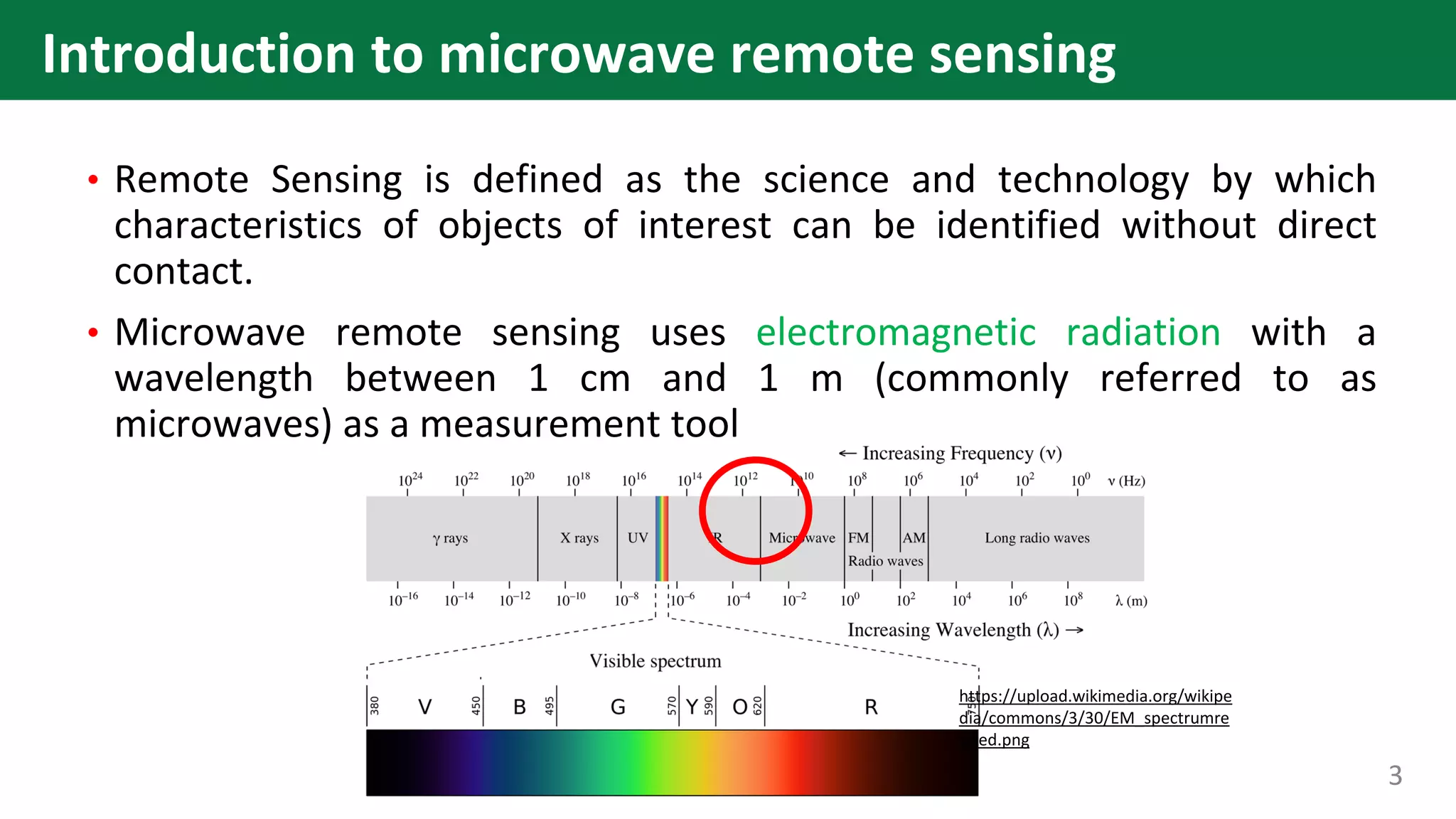
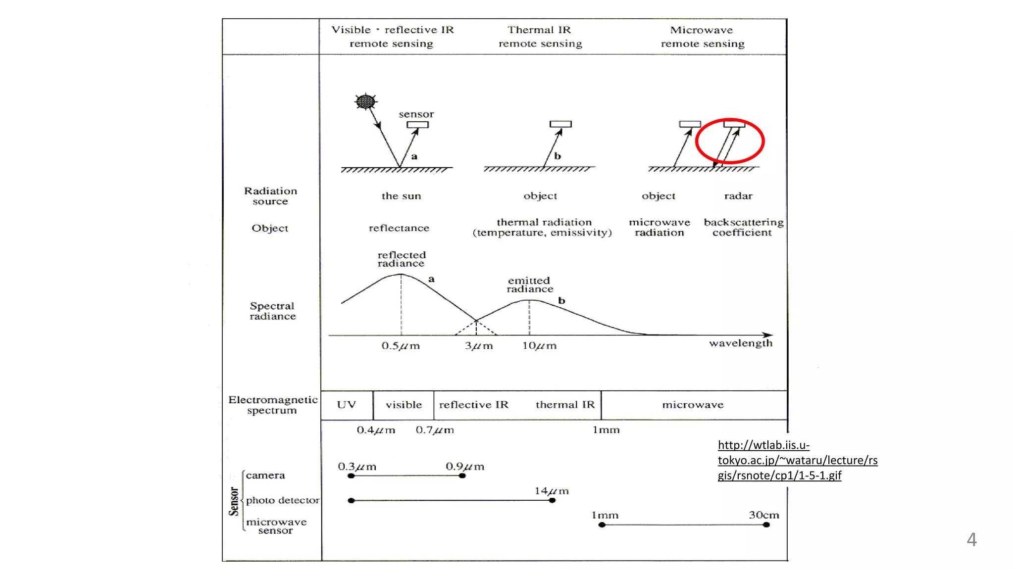
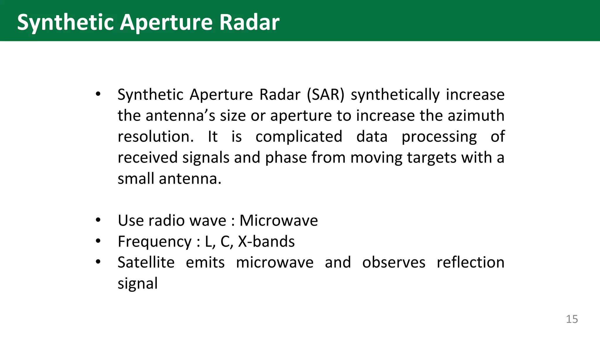
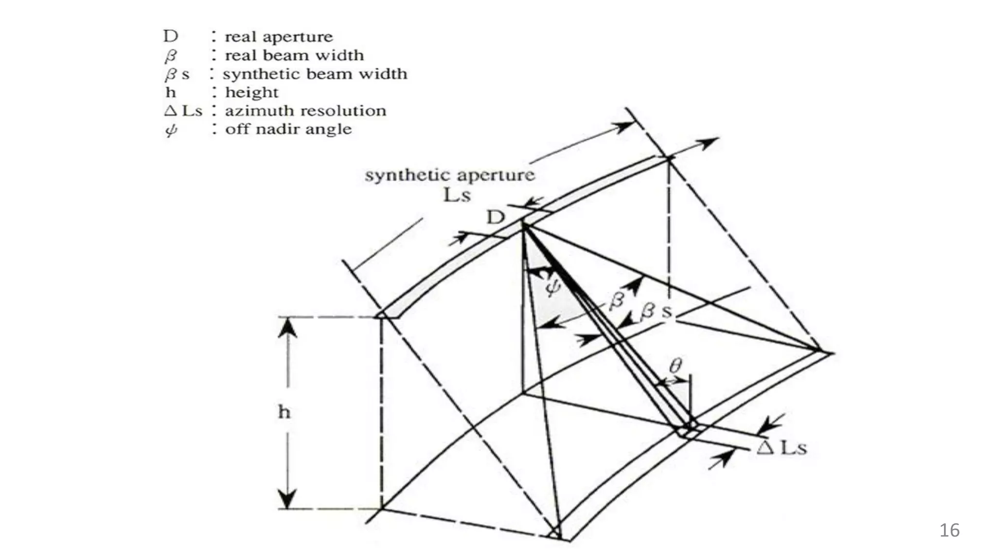
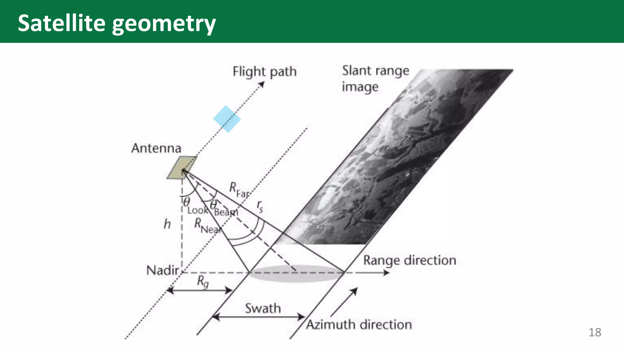
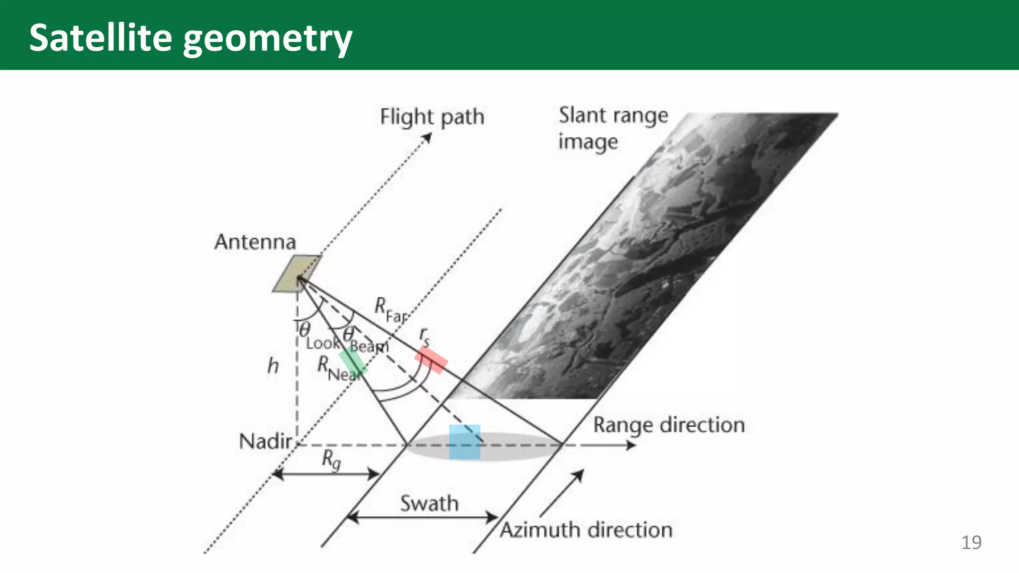
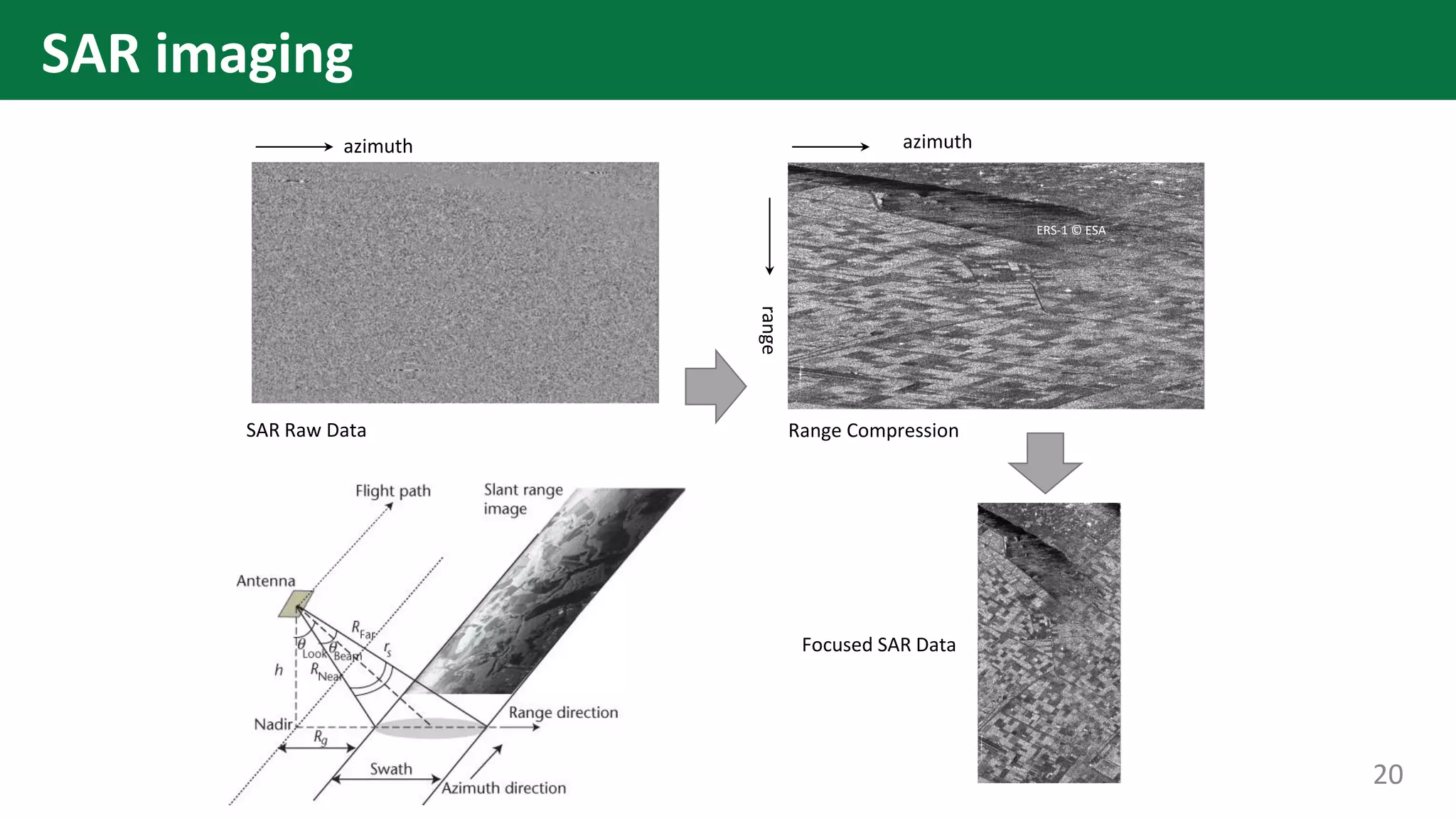
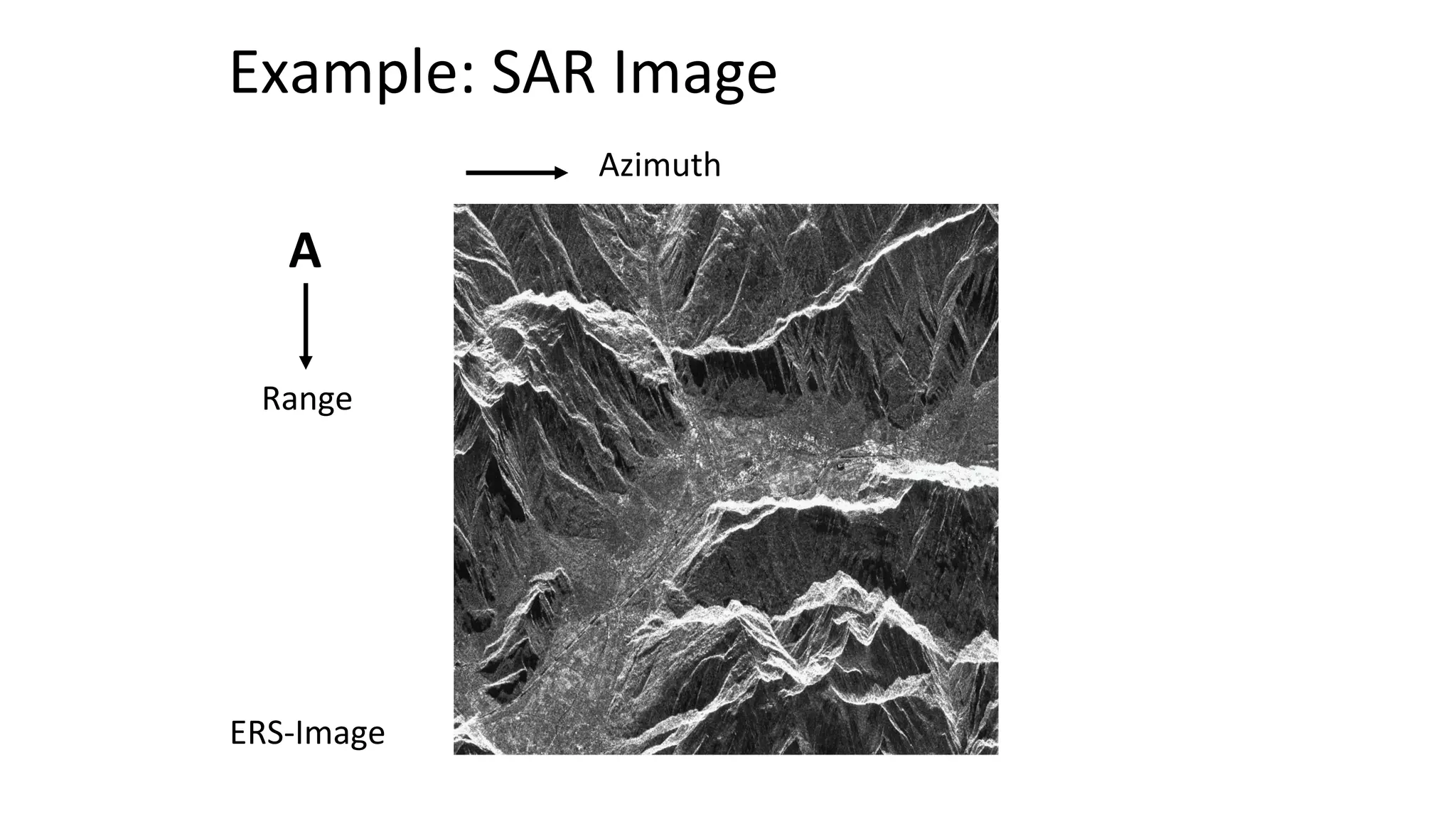
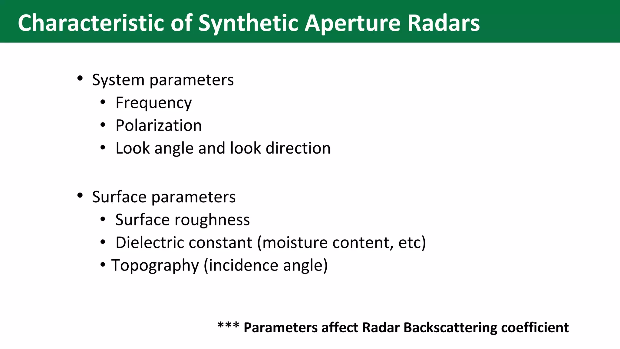
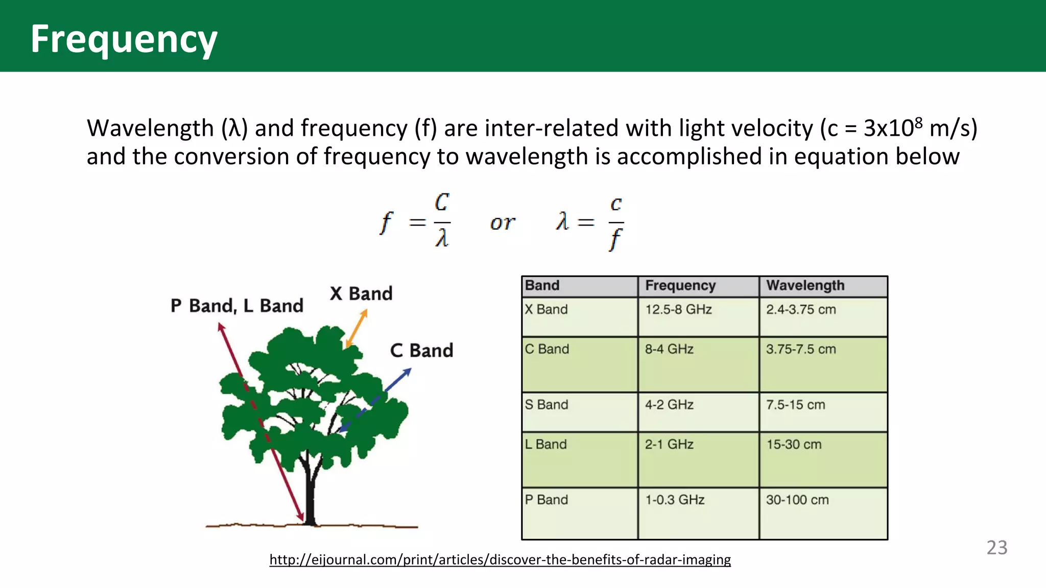
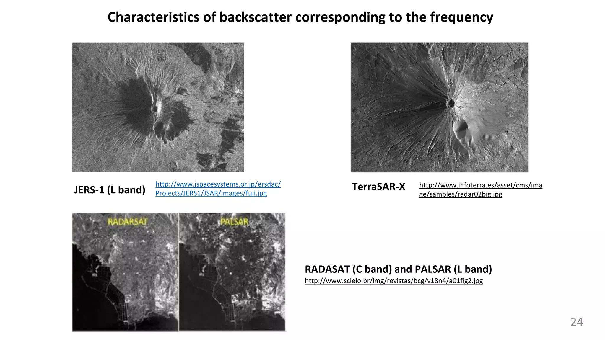
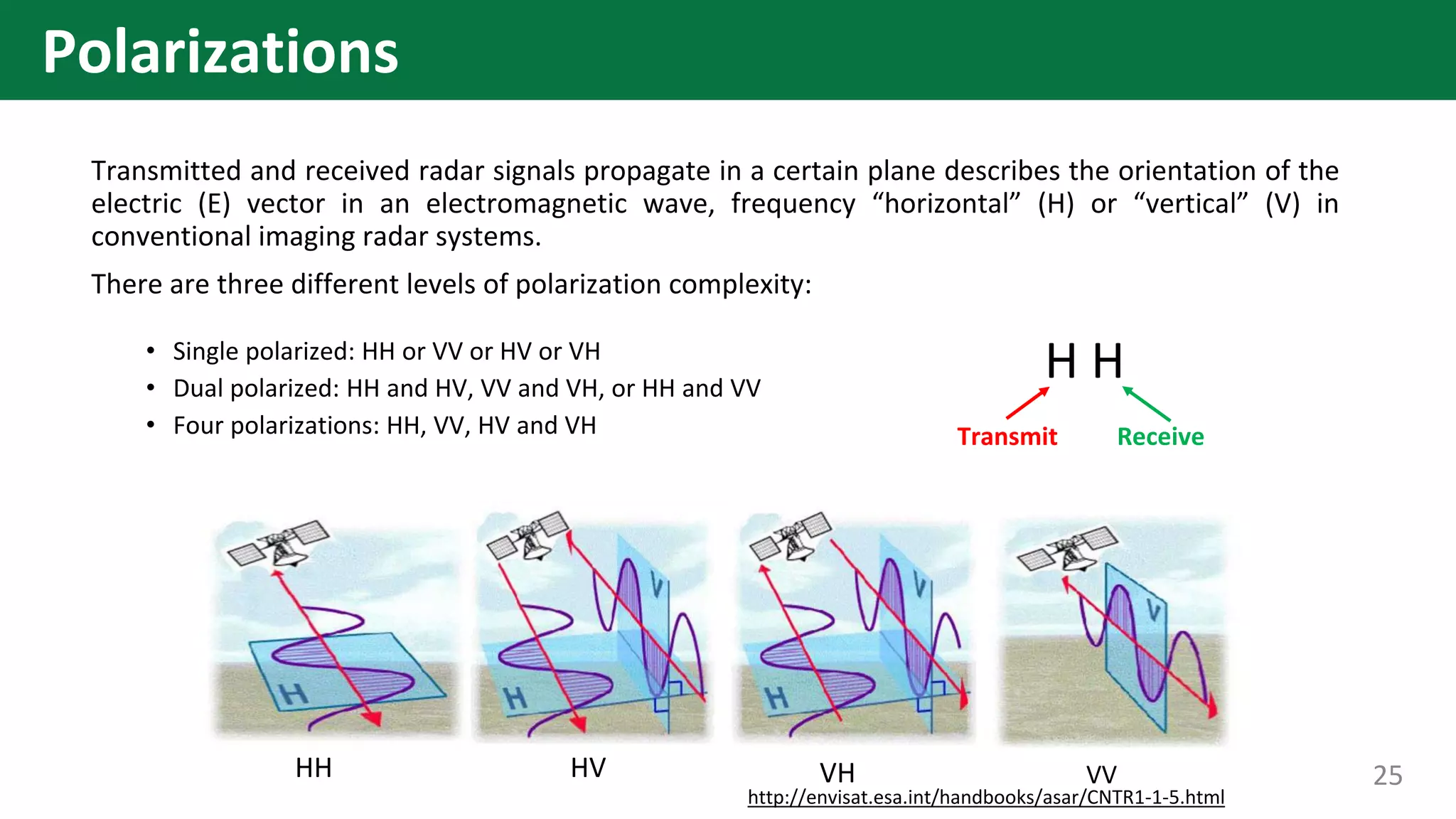
Center for Research and Application for Satellite Remote Sensing
Yamaguchi University
Introduction to Synthetic
Aperture Radar (SAR)
• Remote Sensing and microwave remote sensing
• Side looking radar
• Real aperture radar
• Synthetic aperture radar (SAR)
• SAR geometry
• SAR imaging
• SAR parameters
• Interpretation
• Status and specification
• Advantage and disadvantages
2
Contents
• Remote Sensing is defined as the science and technology by which
characteristics of objects of interest can be identified without direct
contact.
• Microwave remote sensing uses electromagnetic radiation with a
wavelength between 1 cm and 1 m (commonly referred to as
microwaves) as a measurement tool
https://upload.wikimedia.org/wikipe
dia/commons/3/30/EM_spectrumre
vised.png
3
Introduction to microwave remote sensing
http://wtlab.iis.u-
tokyo.ac.jp/~wataru/lecture/rs
gis/rsnote/cp1/1-5-1.gif
4
• Real Aperture Radar (RAR) was the first active sensor to produce imagery of the
terrain from backscattered microwave radiation.
• It transmits a narrow angle beam of pulse radio wave in the range direction at
right or left angles to fight direction (Azimuth direction) and receives the
backscattering from the targets which will be transformed to a radar image from
the received signals.
5
Side Looking Radar
The resolution in the range direction depends on the pulse width.
Azimuth resolution is determined by the beam width.
6
7
8
9
10
11
Radar Pulse Propagation
12
Radar Pulse Propagation
13
Radar Pulse Propagation
Distance = Time/2
14
• Synthetic Aperture Radar (SAR) synthetically increase
the antenna’s size or aperture to increase the azimuth
resolution. It is complicated data processing of
received signals and phase from moving targets with a
small antenna.
• Use radio wave : Microwave
• Frequency : L, C, X-bands
• Satellite emits microwave and observes reflection
signal
15
Synthetic Aperture Radar
16
17
Satellite geometry
18
Satellite geometry
19
Satellite geometry
SAR imaging
azimuth
ERS-1 © ESA
SAR Raw Data
azimuth
range
ERS-1 © ESA
Focused SAR Data
Range Compression
20
Example: SAR Image
ERS-Image
Range
Azimuth
A
• System parameters
• Frequency
• Polarization
• Look angle and look direction
• Surface parameters
• Surface roughness
• Dielectric constant (moisture content, etc)
• Topography (incidence angle)
*** Parameters affect Radar Backscattering coefficient
Characteristic of Synthetic Aperture Radars
Wavelength (λ) and frequency (f) are inter-related with light velocity (c = 3x10⁸ m/s)
and the conversion of frequency to wavelength is accomplished in equation below
http://eijournal.com/print/articles/discover-the-benefits-of-radar-imaging
23
Frequency
Characteristics of backscatter corresponding to the frequency
http://www.infoterra.es/asset/cms/ima
ge/samples/radar02big.jpg
http://www.jspacesystems.or.jp/ersdac/
Projects/JERS1/JSAR/images/fuji.jpg
JERS-1 (L band) TerraSAR-X
http://www.scielo.br/img/revistas/bcg/v18n4/a01fig2.jpg
RADASAT (C band) and PALSAR (L band)
24
Transmitted and received radar signals propagate in a certain plane describes the orientation of the
electric (E) vector in an electromagnetic wave, frequency “horizontal” (H) or “vertical” (V) in
conventional imaging radar systems.
There are three different levels of polarization complexity:
• Single polarized: HH or VV or HV or VH
• Dual polarized: HH and HV, VV and VH, or HH and VV
• Four polarizations: HH, VV, HV and VH
HH HV VH VV
http://envisat.esa.int/handbooks/asar/CNTR1-1-5.html
H H
Transmit Receive
25
Polarizations
HH HV VH VV
Sample data : ALOS PLR mode from http://www.alos-restec.jp/en/staticpages/index.php/service-sampledata-04
26
Polarizations
HH HV VH VV
Sample data : ALOS PLR mode from http://www.alos-restec.jp/en/staticpages/index.php/service-sampledata-04
Sensitive Sensitive
Water is dark Water is dark
High backscattering High backscattering
Low backscattering Low backscattering
27
Polarizations
https://terpconnect.umd.edu/~gsun/radar/scatsurf.jpg
28
Surface roughness
Long wavelength
Short wavelength
https://www.mdpi.com/2072-4292/10/6/916
29
Surface roughness
Saturated soil →a high dielectric →strong reflector.
http://www.geog.ucsb.edu/~jeff/115a/remote_sensing/radar/radarroughness.jpg
Dry soil →low dielectric constant →little radar energy will be reflected.
Dielectric constant depends on the type of material as well as its moisture state
30
Dielectric constant
https://arset.gsfc.nasa.gov/sites/default/files/water/Brazil_2017/Day1/S1P2.pdf
31
http://www.mdpi.com/sensors/sensors-09-
01876/article_deploy/html/images/sensors-09-01876f1-1024.png http://www.alspergis.altervista.org/lezione/07/05.png
32
Incidence angle and look angle
https://history.nasa.gov/JPL-93-24/p48.htm
Ground range
33
Radar foreshortening
Radar layovering
https://history.nasa.gov/JPL-93-24/p48.htm
1st point
2nd point
34
Radar shadowing
https://history.nasa.gov/JPL-93-24/p48.htm
35
Radar shadowing
http://step.esa.int/docs/tutorials/S1TBX%20SAR%20Basics%20Tutorial.pdf
S S
36
http://step.esa.int/docs/tutorials/S1TBX%20SAR%20Basics%20Tutorial.pdf
F F
37
Radar foreshortening
http://step.esa.int/docs/tutorials/S1TBX%20SAR%20Basics%20Tutorial.pdf
L Low backscattering
38
Radar layovering
http://step.esa.int/docs/tutorials/S1TBX%20SAR%20Basics%20Tutorial.pdf
39
Ground range
Slant range
http://envisat.esa.int/handbooks/asar/CNTR1-1-5.html 40
SAR images obtained with different incidence angles
ALOS sample image from http://www.alos-restec.jp/en/staticpages/index.php/service-sampledata-17 41
Slant range to ground range
Differences of multi-spectral and SAR
Optical Sensor SAR
Platform
Radiation
Spectrum
Frequency
Polarimetry
Interferometry
Acquisition time
Weather
Airborne/spaceborne Airborne/spaceborne
Reflected sunlight Own radiation
Visible/infrared Microwave
Multi-frequency Single/Multi-frequency
N.A.
N.A.
Day time
Blocked by clouds See through clouds
Day/night
Polarimetric phase
Polarimetric phase
42
43
44
Status of SAR Satellites
45
SAR sensors 2000 2001 2002 2003 2004 2005 2006 2007 2008 2009 2010 2011 2012 2013 2014 2015 2016 2017 2018
ERS-2
RADARSAT-1
ENVISAT ASAR
ALOS PALSAR
TerraSAR-X
RADARSAT-2
COSMO-SkyMed
RISAT-2
RISAT-1
HJ-1C
Komsat-5
PAZ
ALOS-2
SENTINEL 1a
SENTINEL 1b
SAOCOM 1A
SAOCOM 1B
Radarsat Constellation
1/2/3
X band (2.4-3.75 cm.) C band (3.75 -7.5 cm.) S band (7.5-15 cm.) L band (15-30 cm.)
11
24
15
25
25
4
28
11
14
12
12
16
16
4
Repeat day
ALOS-2
Modes Spotlight
Strip Map
Scan SAR
Nominal Resolution Spotlight 1-3 m
Strip Map 3-10 m
ScanSAR: 100 m
Swath width Spotlight: 25 km
Strip Map: 50-70 km
ScanSAR: 350 or 490 km
Band L- Band
Polarisation SP: HH or VV or HV
DP: HH+HV or VV+VH
FP: HH+HV+VH+VV
Nominal Look Direction Left or Right
Incidence angles between 8 and 70 degrees
The PALSAR-2 aboard ALOS-2 is an L-band Synthetic Aperture
Radar(SAR) sensor, a microwave sensor that emits L-band radio
waves and receives their reflection from the ground to acquire
information
46
ALOS-2 products
Level Definition Format
Level 1.1
This is complex number data on the slant range following
compression of the range and azimuth. As one-look data, it
includes phase information and will be the basis for later
processing. In wide-area mode, image files are created for each
scan.
CEOS SAR/GeoTIFF
Level 1.5
This is multi-look data on the slant range from map projection
amplitude data, with range and azimuth compressed.
CEOS SAR/GeoTIFF
Level 2.1
Geometrically corrected (orthorectified) data using the digital
elevation data from Level 1.1.
CEOS SAR/GeoTIFF
Level 3.1
Image quality-corrected (noise removed, dynamic range
compressed) data from Level 1.5.
CEOS SAR/GeoTIFF
47
Sentinel-1
Sentinel-1 is a two-satellite constellation with the prime objectives
of Land and Ocean monitoring by the European Space Agency. The
goal of the mission is to provide C-Band SAR data
• Orbit Type: Sun-synchronous, near-polar, circular
•Inclination: 98.18°
• Repeat Cycle: 175 orbits in 12 days
48
Sentinel-1 products
https://sentinel.esa.int/web/sentinel/user-guides/sentinel-1-sar/product-types-processing-levels 49
• ALOS-2
• https://auig2.jaxa.jp
• Sentinel-1
• https://scihub.copernicus.eu/dhus/#/home
50
Data Hub
Advantages:
• Observe both night and day time
• Small dependence on atmospheric
conditions such as solar radiation, cloud
cover
• Controllability of the emitted
electromagnetic radiation such as power,
frequency, polarization, radiation direction
and etc.
Disadvantages:
• Black and white image
• Difficult to understand without
http://www.eorc.jaxa.jp/en/hatoyama/etc/images/use/image/rn_12_1.jpg
http://www.eorc.jaxa.jp/en/hatoyama/etc/images/use/image/rn_12_2.jpg
Advantages and Disadvantages of SAR

Introduction to Synthetic Aperture Radar (SAR)