Downloaded 1,237 times

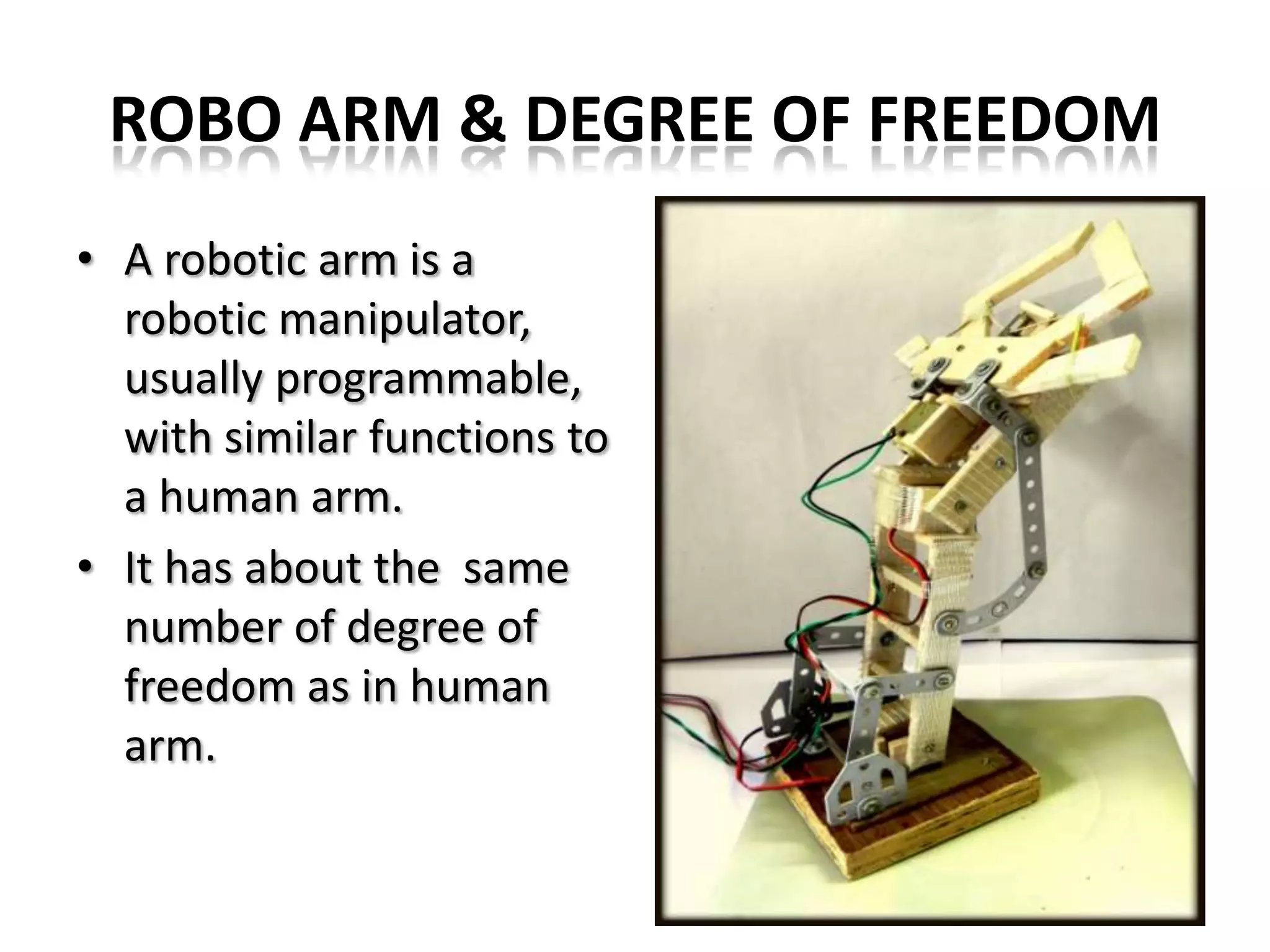
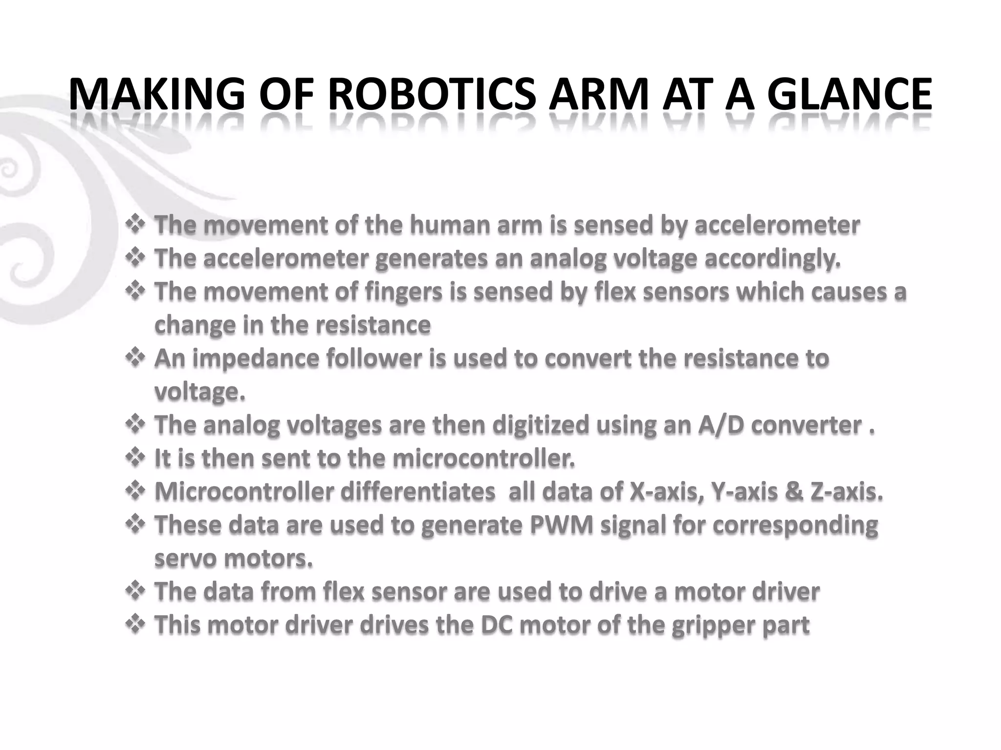
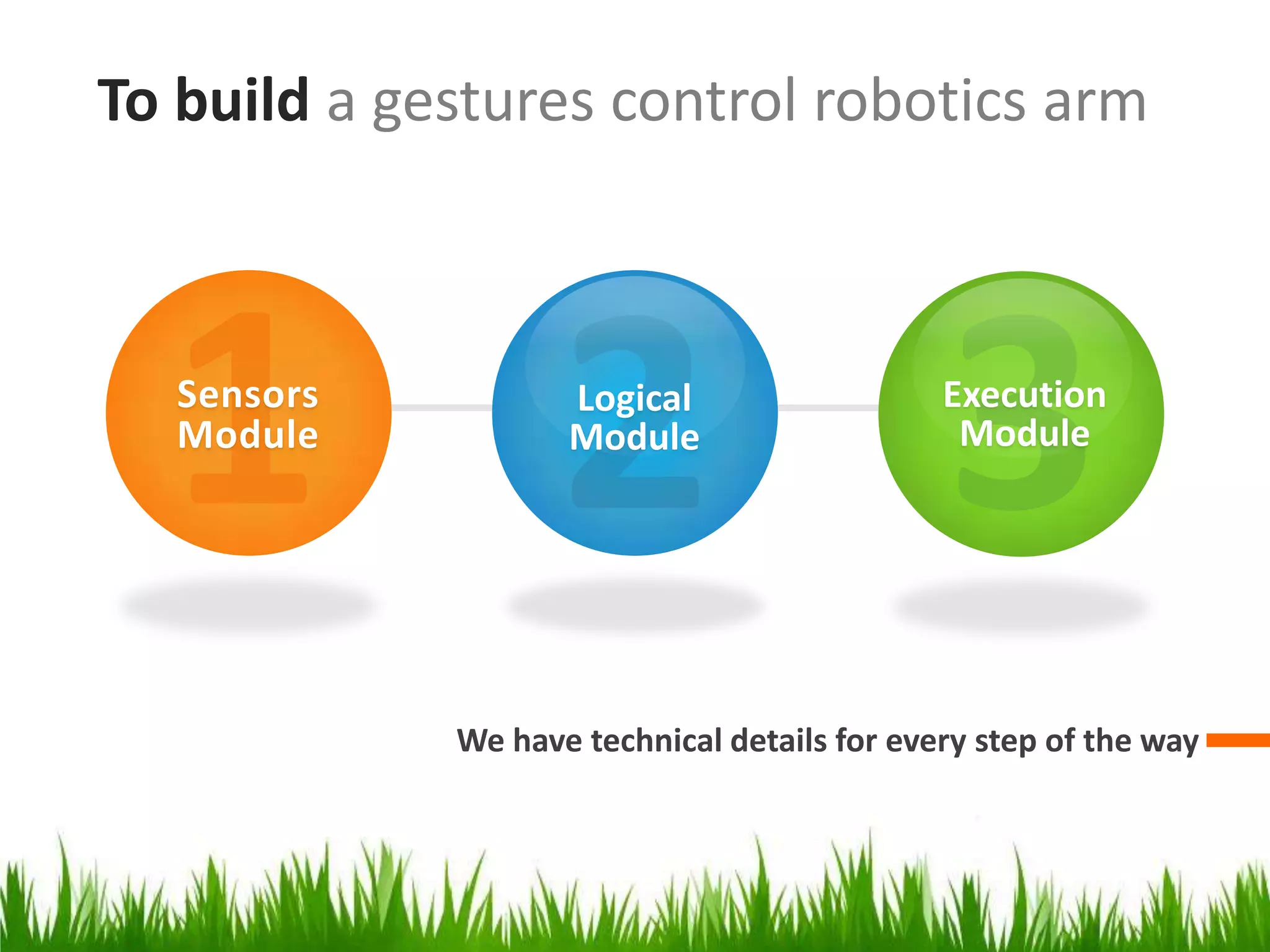
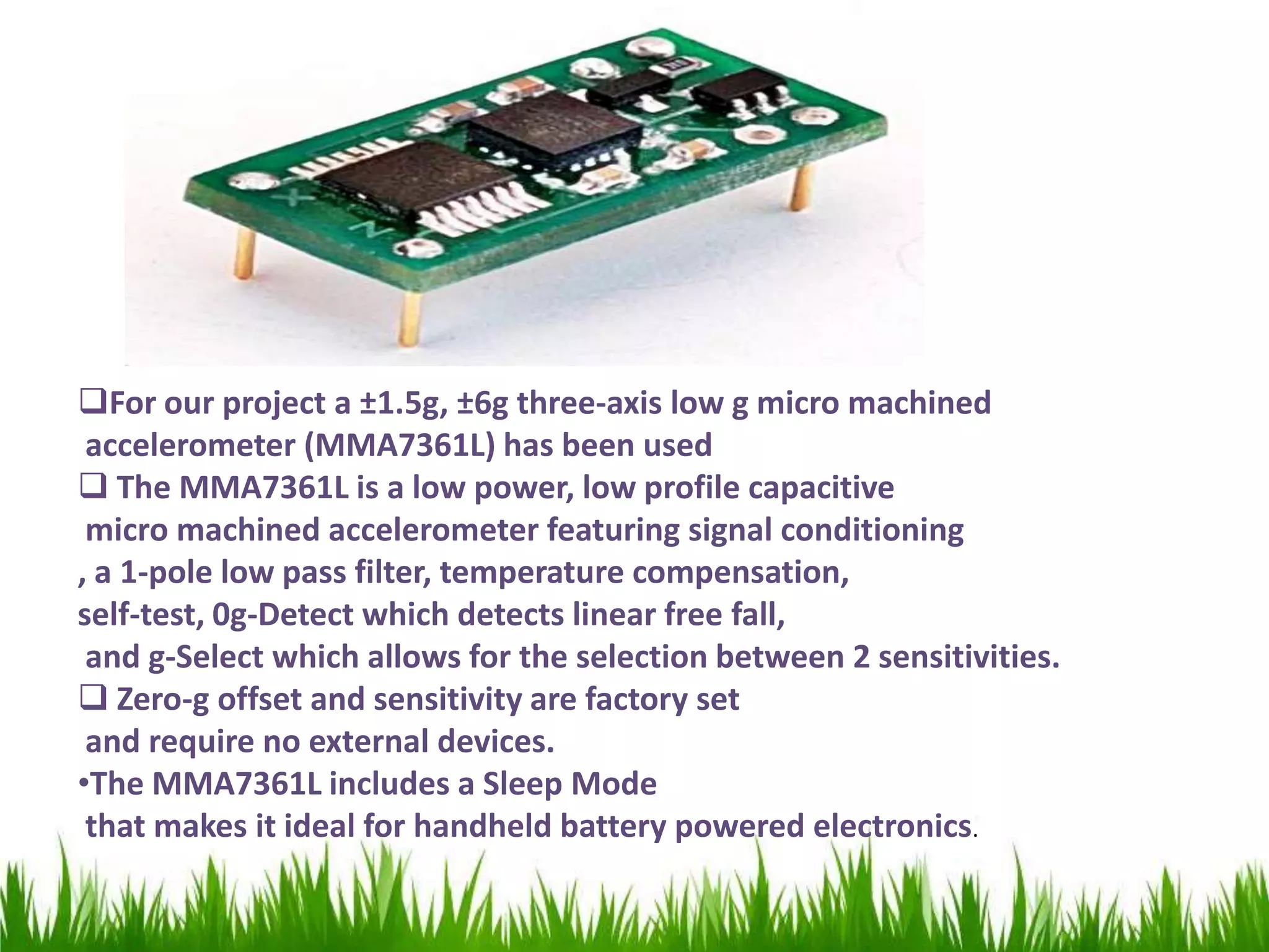
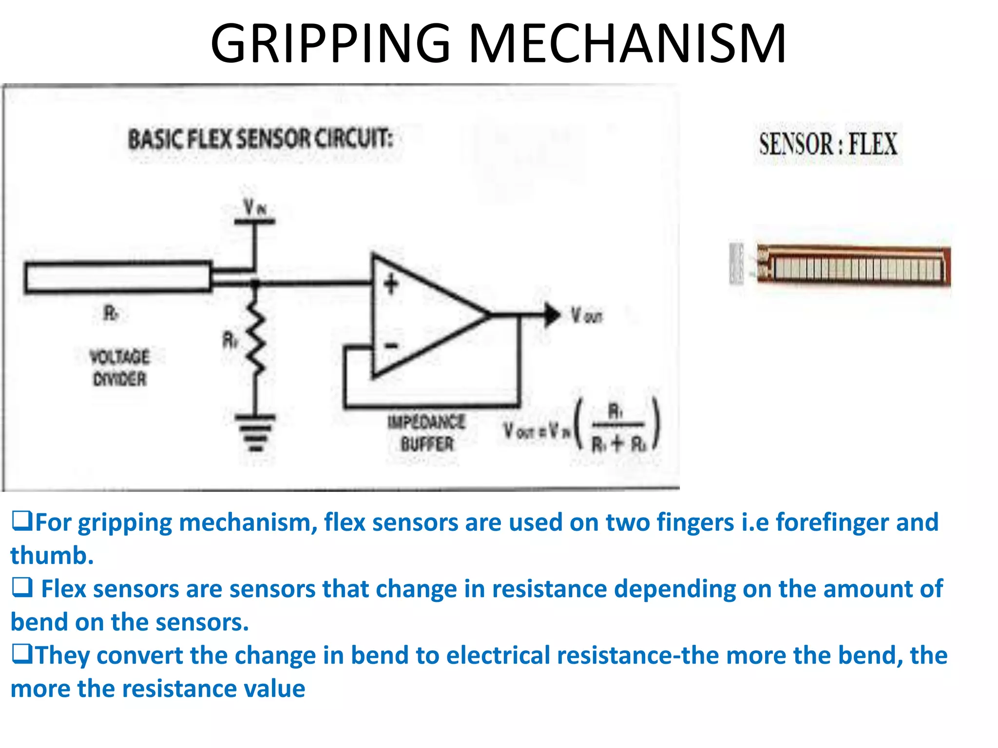
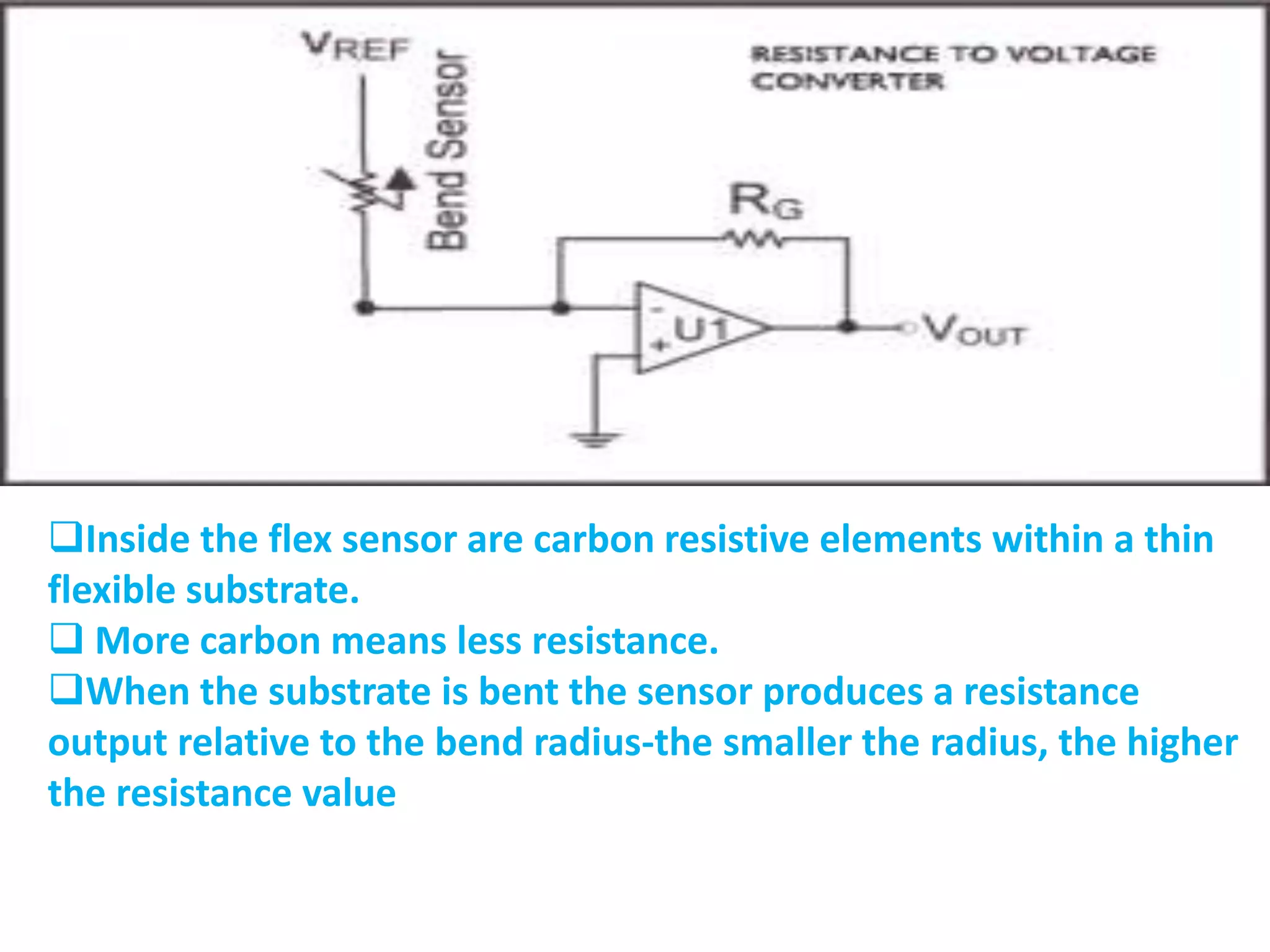

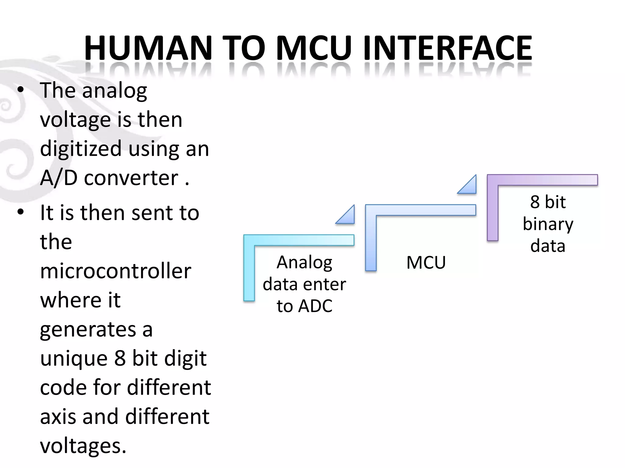
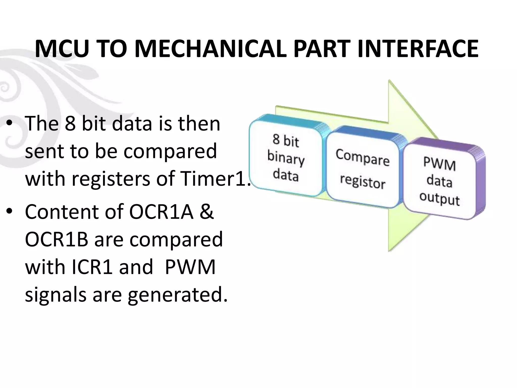
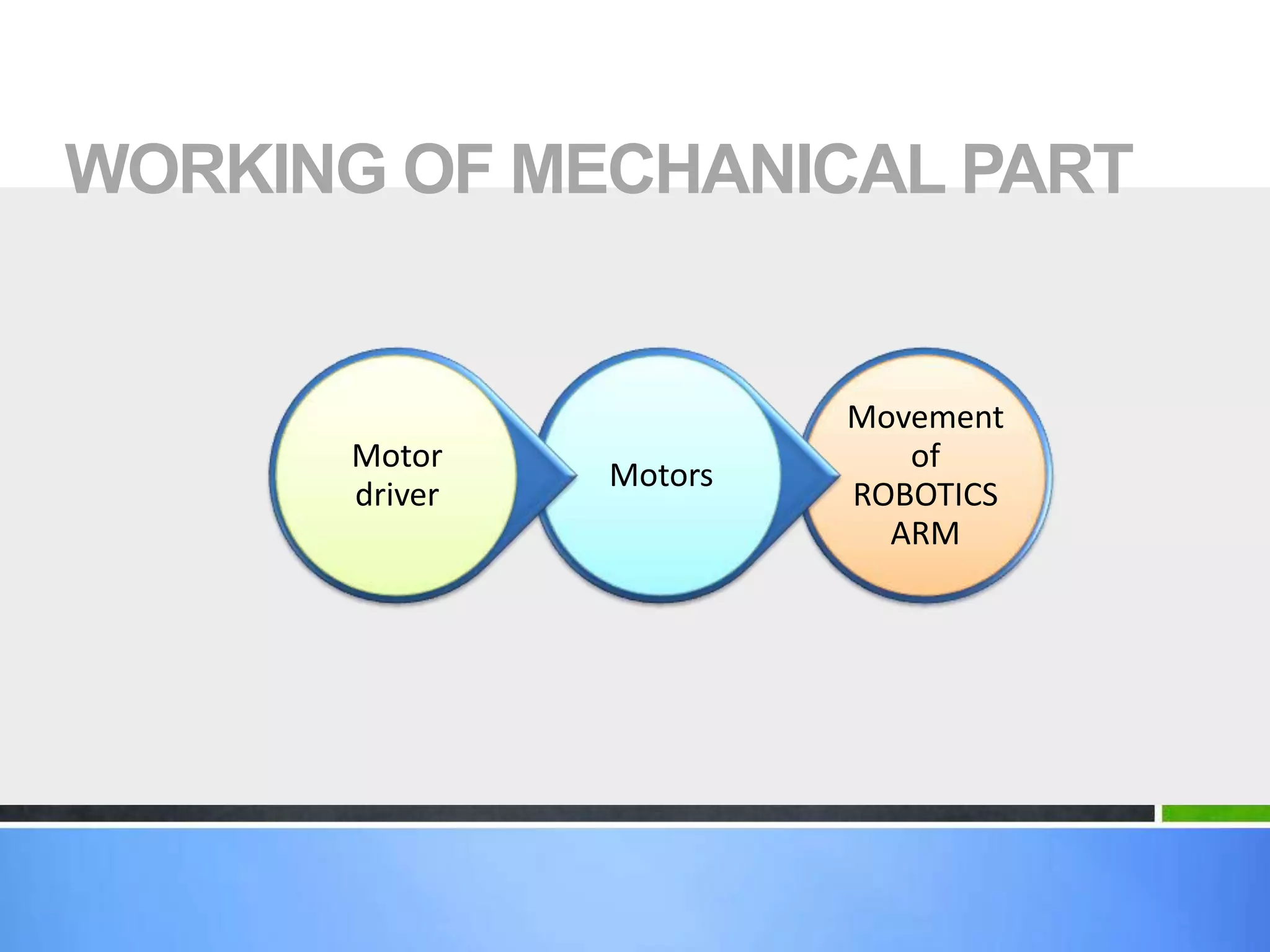
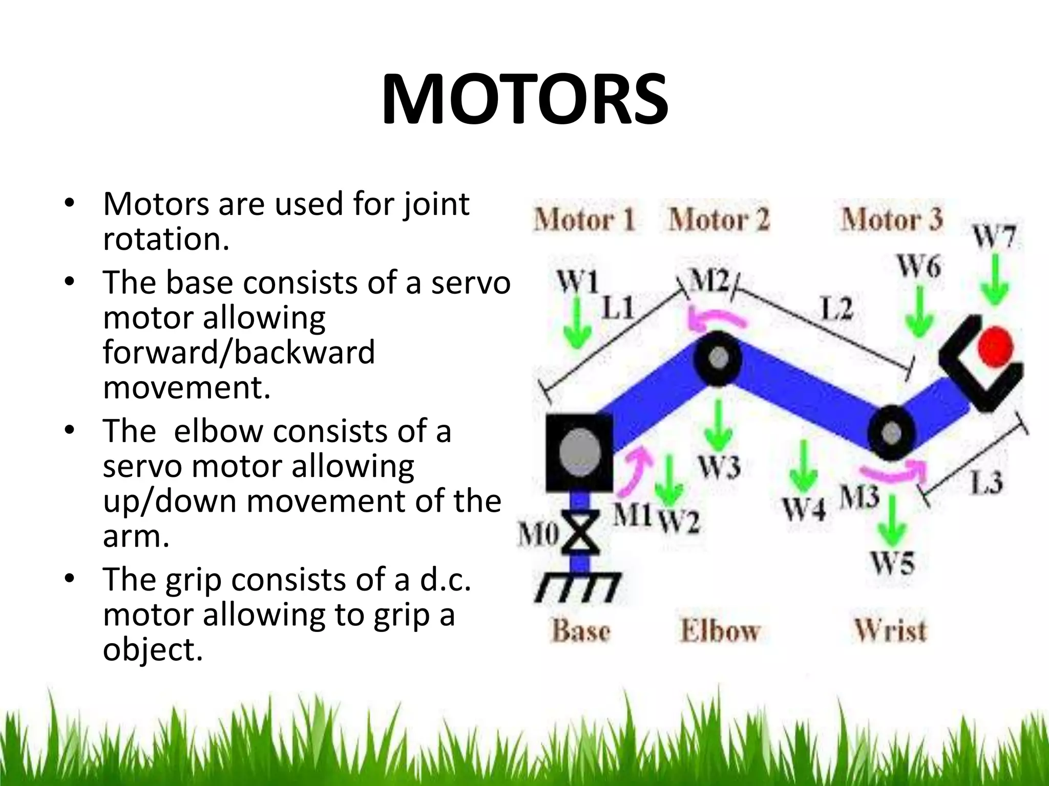
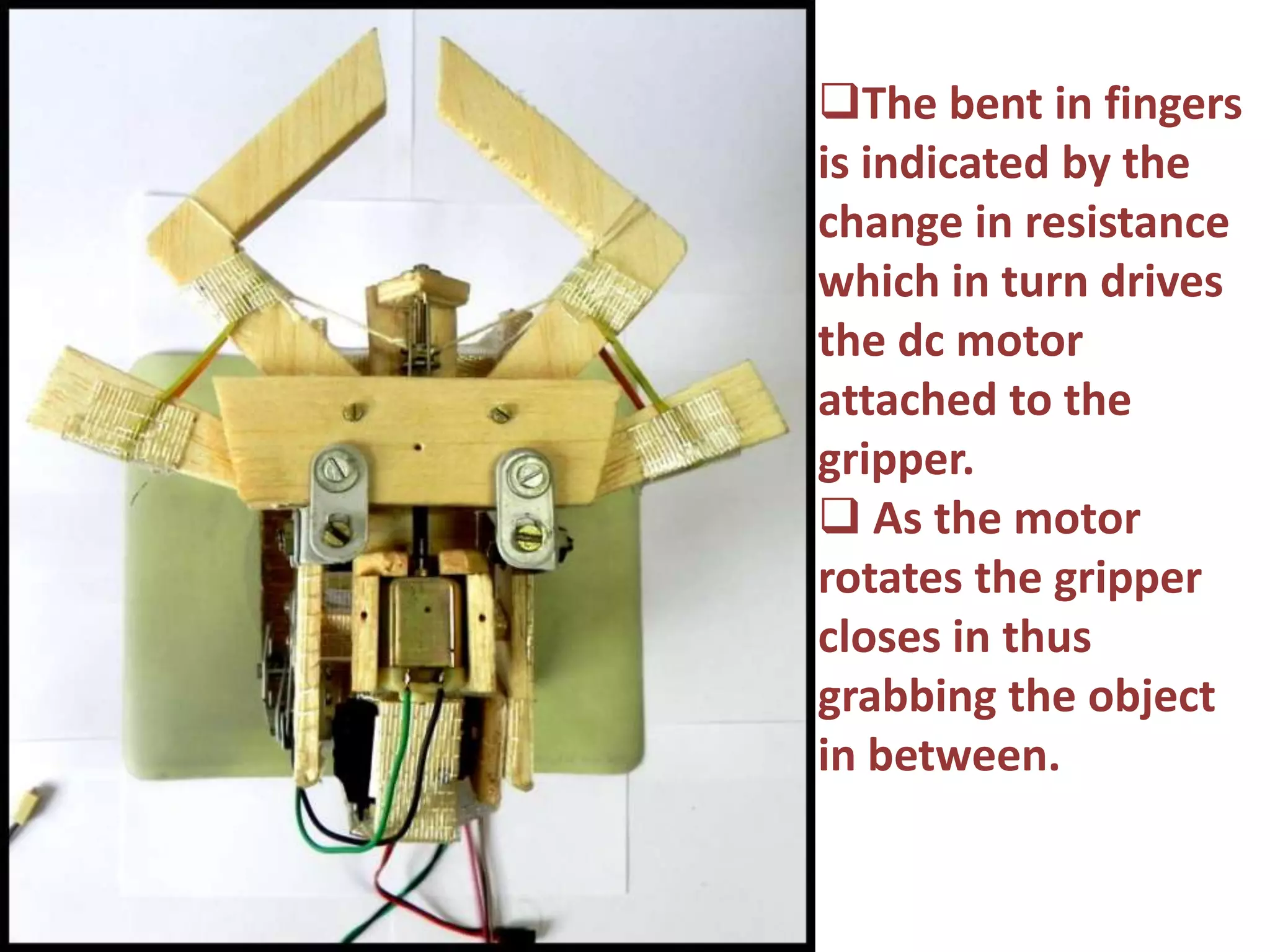
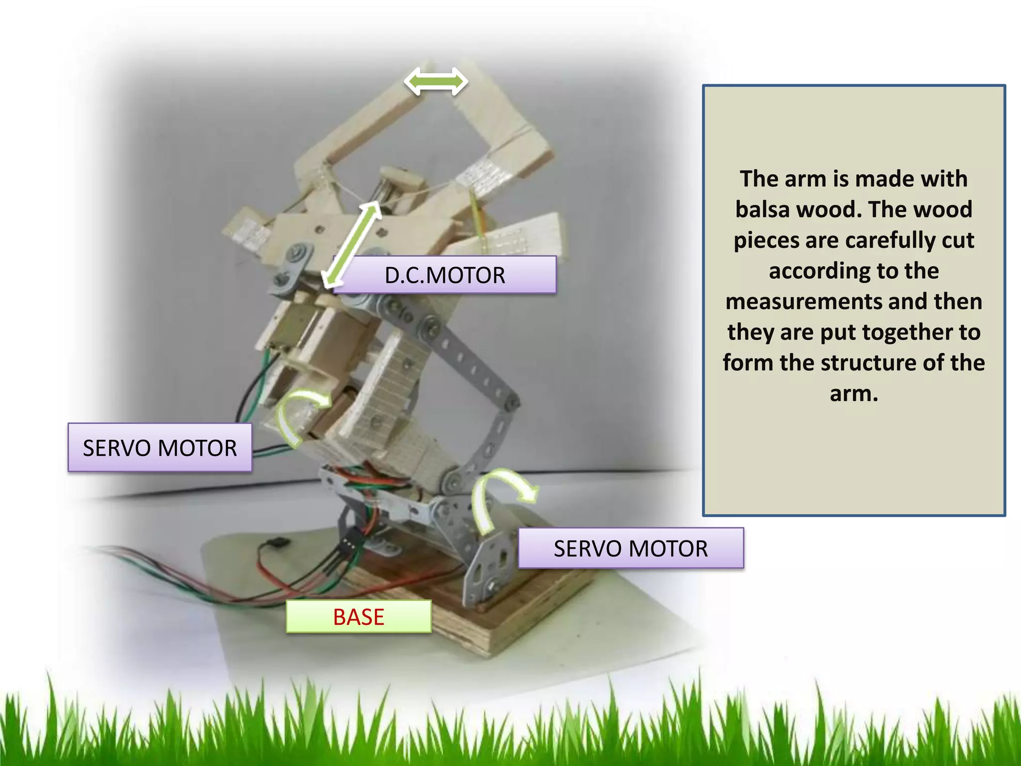
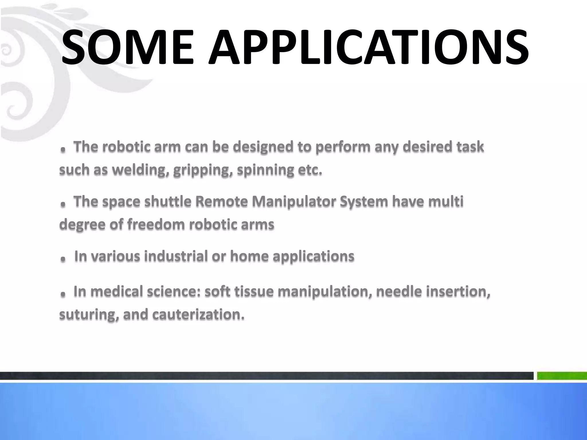
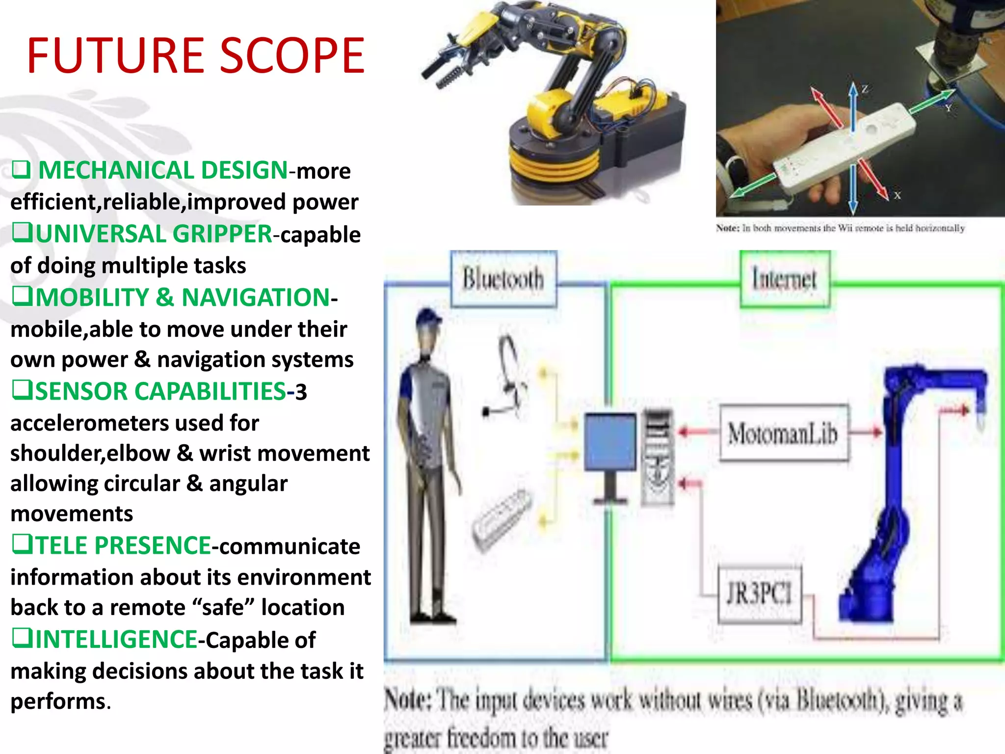


The document introduces a robotic arm project built by students to be controlled through hand gesture recognition. The aim was to build an arm that can grip objects. Key features include using an accelerometer and flex sensors to capture hand gestures which are processed by a microcontroller to drive servo and DC motors that move the arm and gripper. Applications are discussed like industrial uses and medical procedures. Future improvements discussed are more degrees of freedom, intelligence, and mobility. In conclusion, robotic arms are complex but help with difficult, unsafe, or boring tasks.