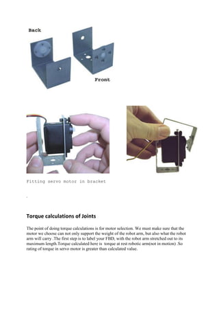
This document describes a robotic arm created by team members Ritesh Kumar, Sugam Anand, and Ritesh Gautam. The robotic arm has 4 degrees of freedom and can lift objects up to 150g while reaching 35cm. It is controlled through a computer interface and uses servomotors to allow for rotation of each joint. The arm was designed to be lightweight, robust, and easy to operate for non-experts through the use of a graphical user interface.


![The code used for communication is as follows:
#include”conio.h”
#include”Tserial.cpp”
#include”highgui.h”
#include”cv.h”
#include”string.h”
#include”stdio.h”
Void mainsending(char* ch)
{ Tserial *com;
Com=new Tserial ();
Com->connect(“COM1”,9600,spNONE);
if (com!=0)
{ com->sendArray(ch,4);
com->disconnect(); }
else printf("not sent");
}
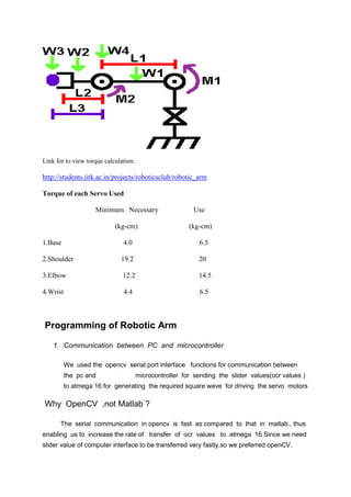
2. Programming the Atmega 16
The main function of atmega 16 is to generate square wave signal at 50Hz to control
5 servo motor.It receives slider value(desired angle for particular servo) from the
computer and generate square wave as required.
The desired frequency is generated with the help of TIMER0 in atmega 16.Code
used for
interrupt [TIM0_COMP] void timer0_comp_isr(void)
{ count++;
if(count>=SERVO_TIME_PERIOD)
{ count=0;
PORTA.0=1;
PORTA.1=1;](https://image.slidesharecdn.com/arm-160519012950/85/Arm-8-320.jpg)
![PORTA.2=1;
PORTA.3=1;
PORTA.4=1;
}
if(count>=x[0])
PORTA.3=0;
if(count>=x[1])
PORTA.0=0;
if(count>=x[2])
PORTA.1=0;
if(count>=x[3])
PORTA.2=0;
if(count>=x[4])
PORTA.4=0; }
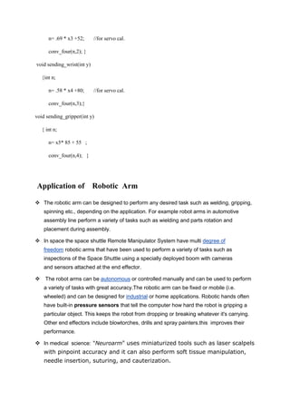
Programming Methodolgy
The data is transferred from the openCV GUI in following format:- a123 .The first alphabetical
character denoted the servo to be activated and the later digits denote the angle at which that particular
servo has to rotate.
void sending_base(int y)
{ int i,n;
n= .58 * x1 +52; //for servo cal.
conv_four(n,0);}
void sending_shoulder(int y)
{int n;
n= .58 * x2 +62; //for servo cal.
conv_four(n,1); }
void sending_elbow(int y)
{ int n;](https://image.slidesharecdn.com/arm-160519012950/85/Arm-9-320.jpg)


![[IJET-V1I4P11] Authors :Wai Mar Myint, Theingi](https://cdn.slidesharecdn.com/ss_thumbnails/ijet-v1i4p11-150811160919-lva1-app6892-thumbnail.jpg?width=640&height=640&fit=bounds)


