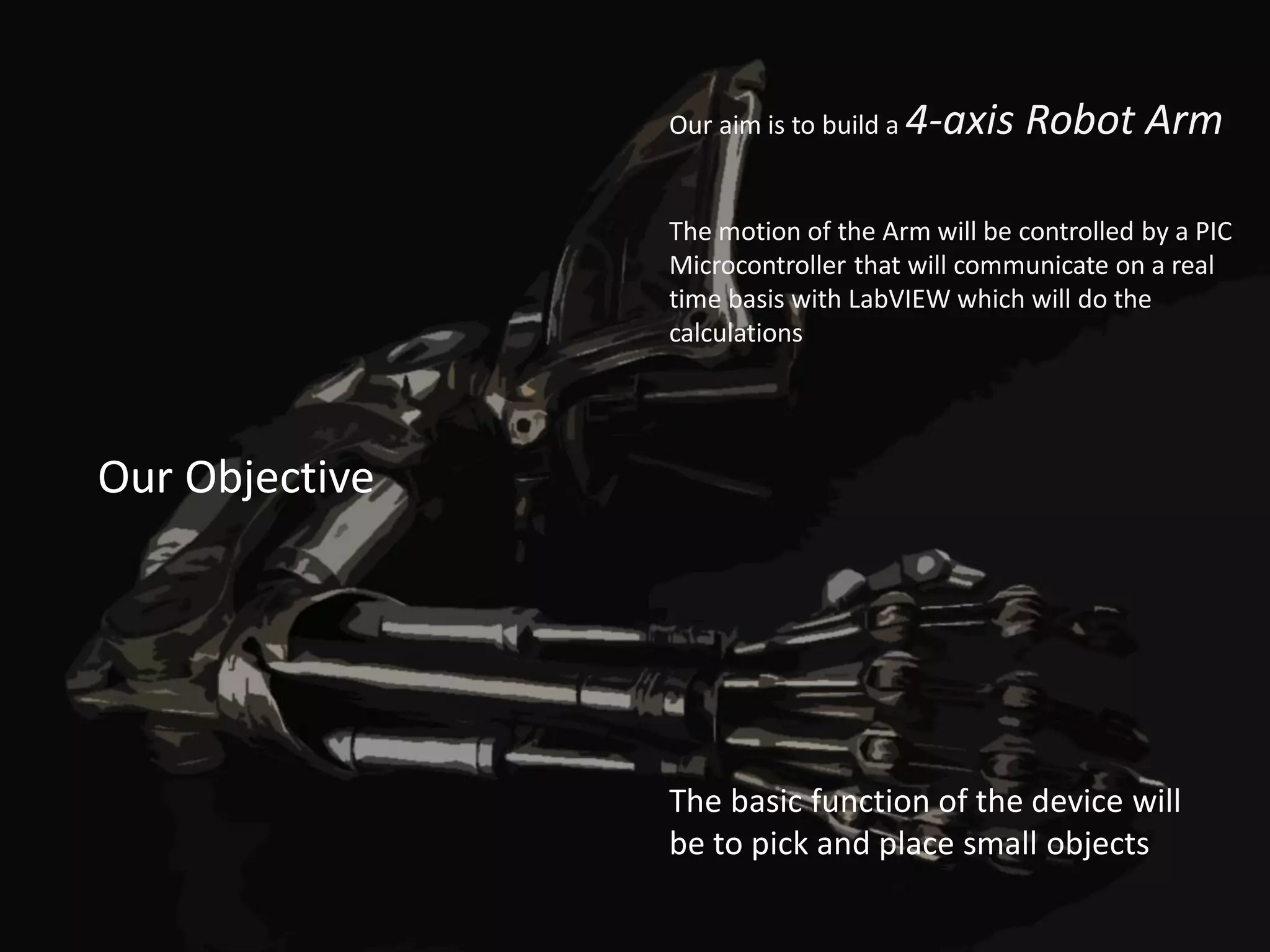
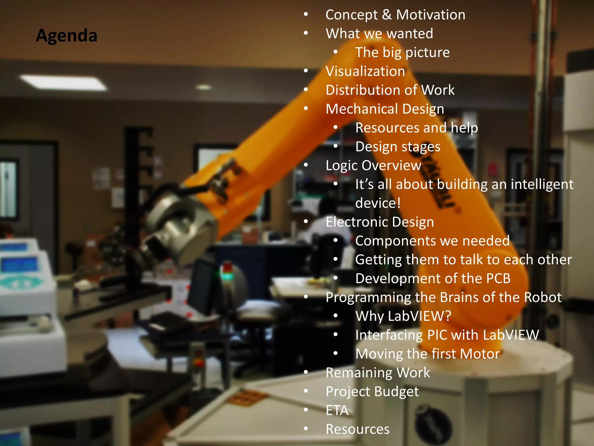
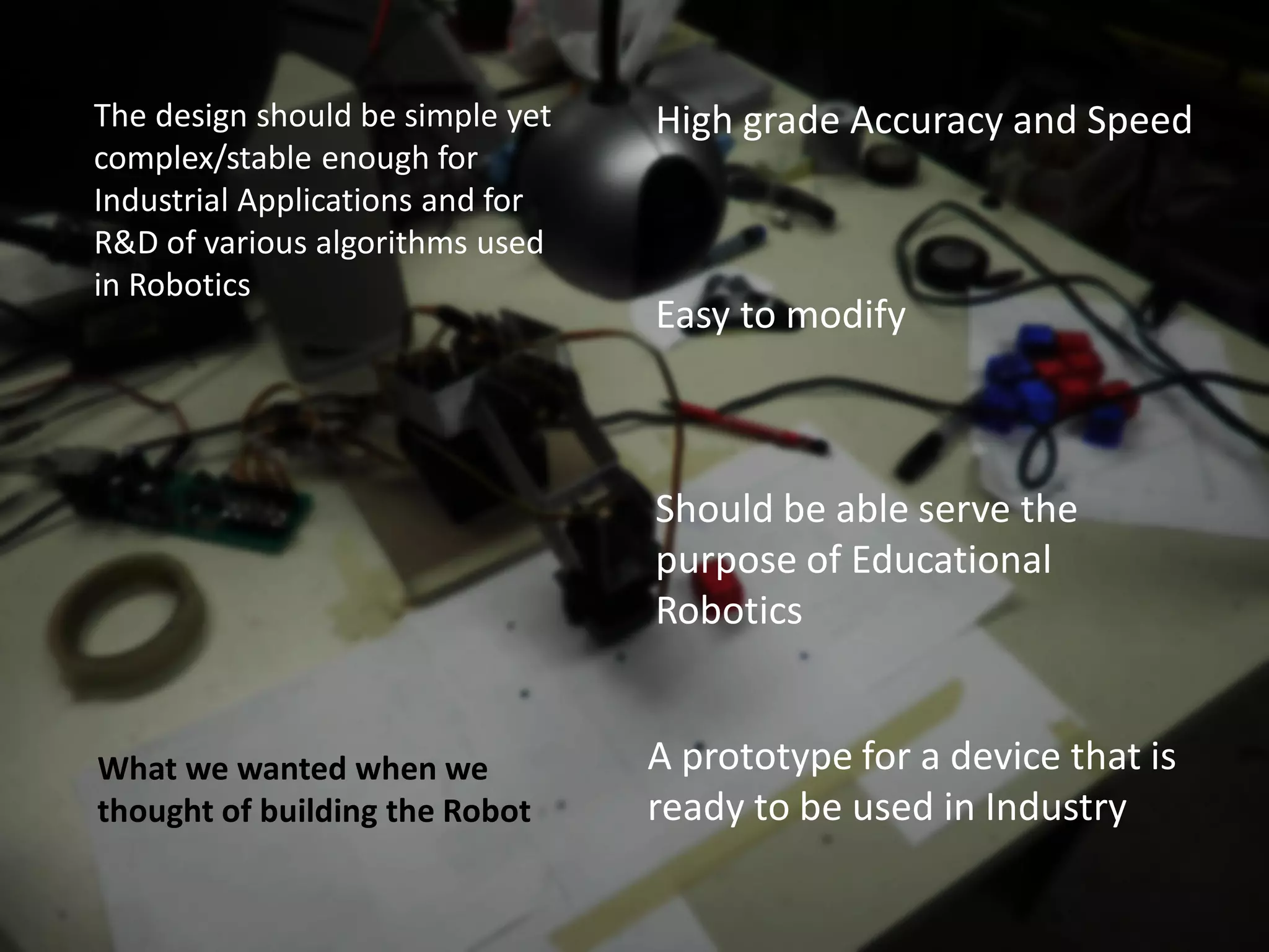
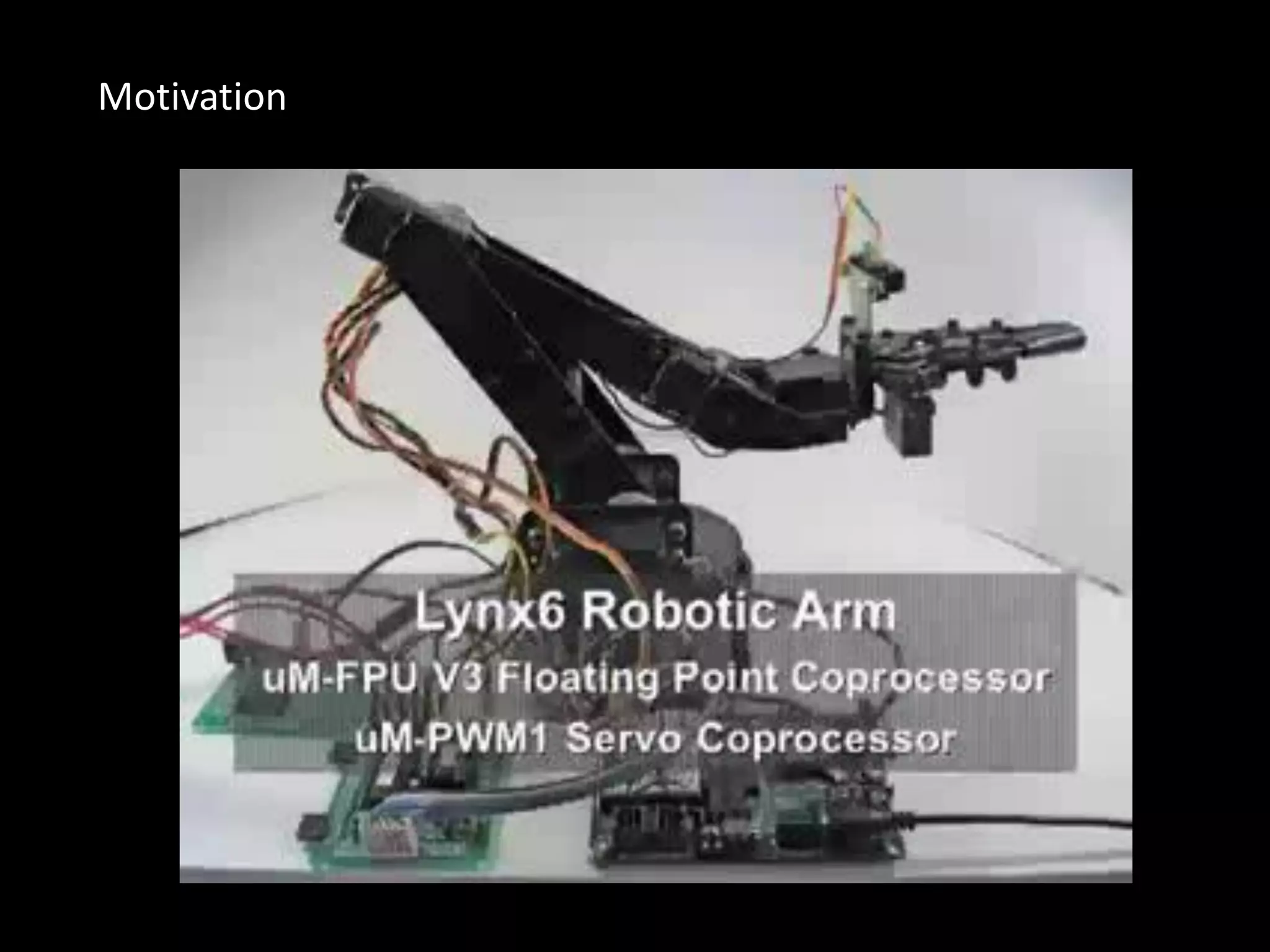
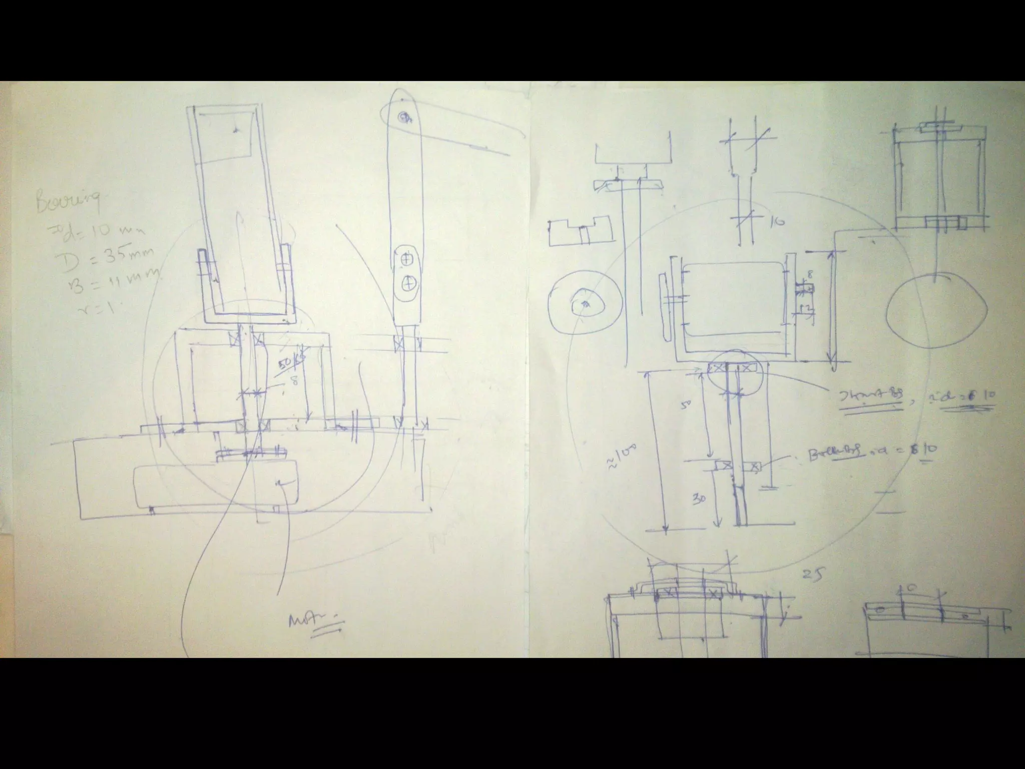
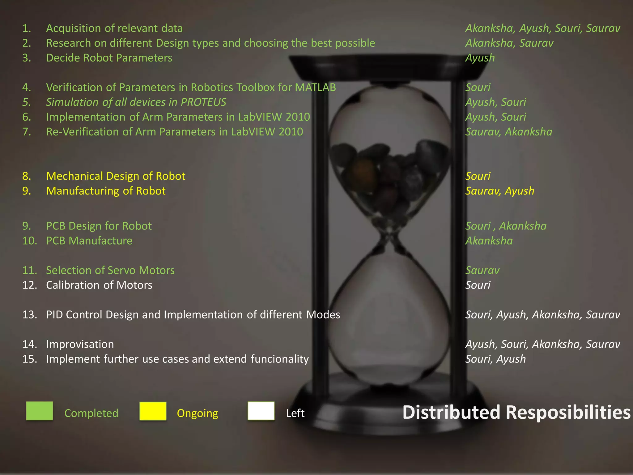
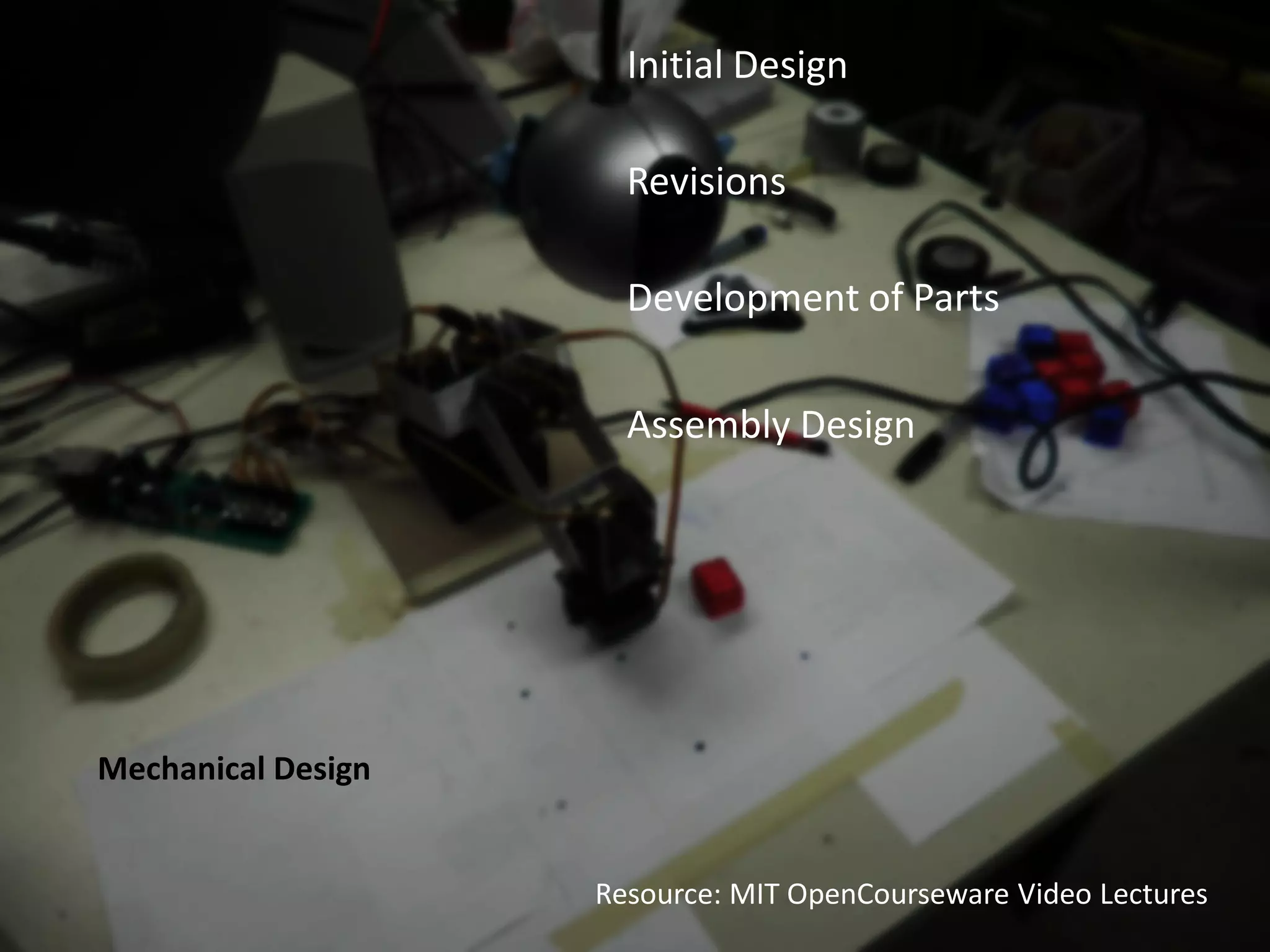
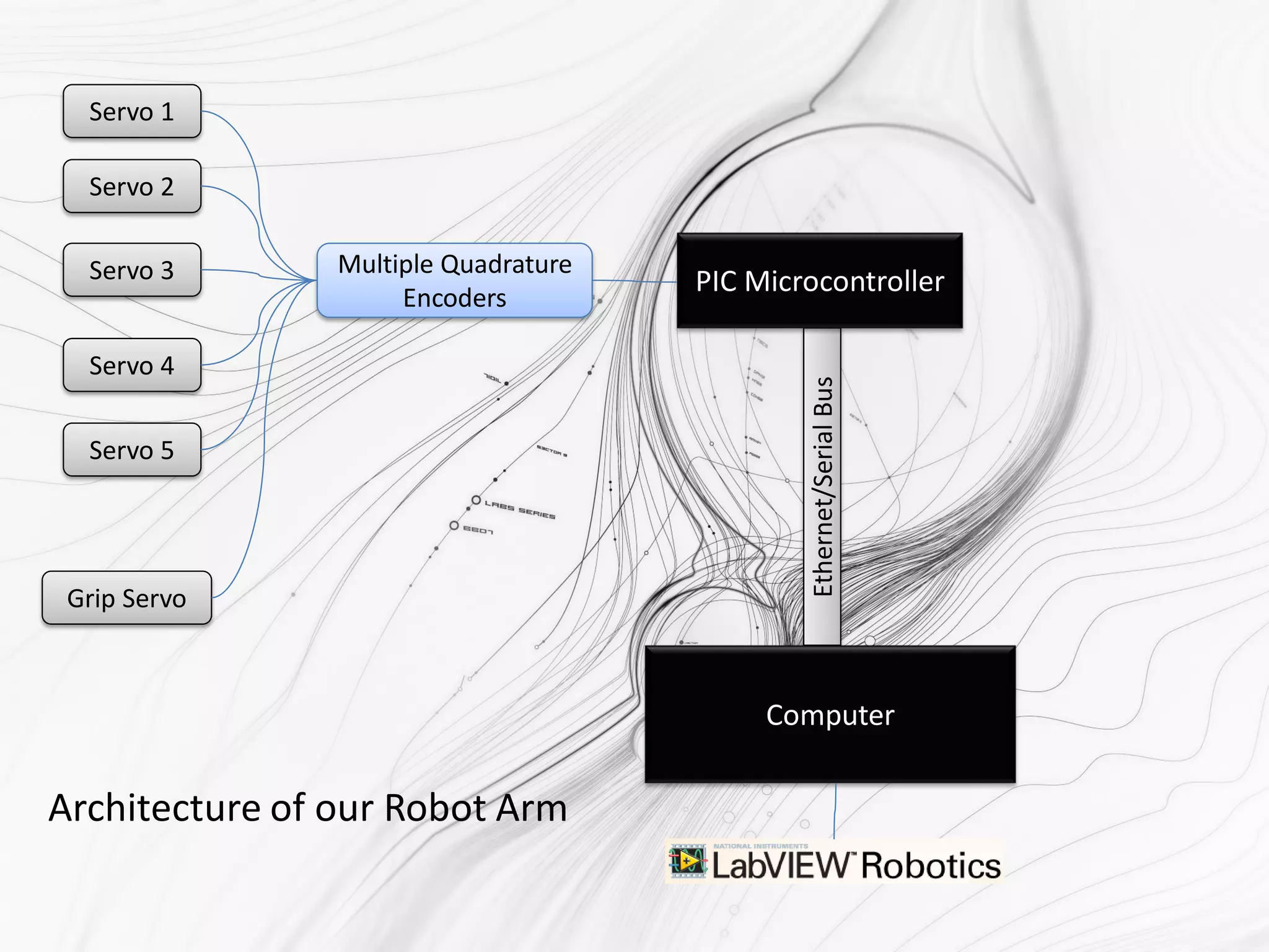
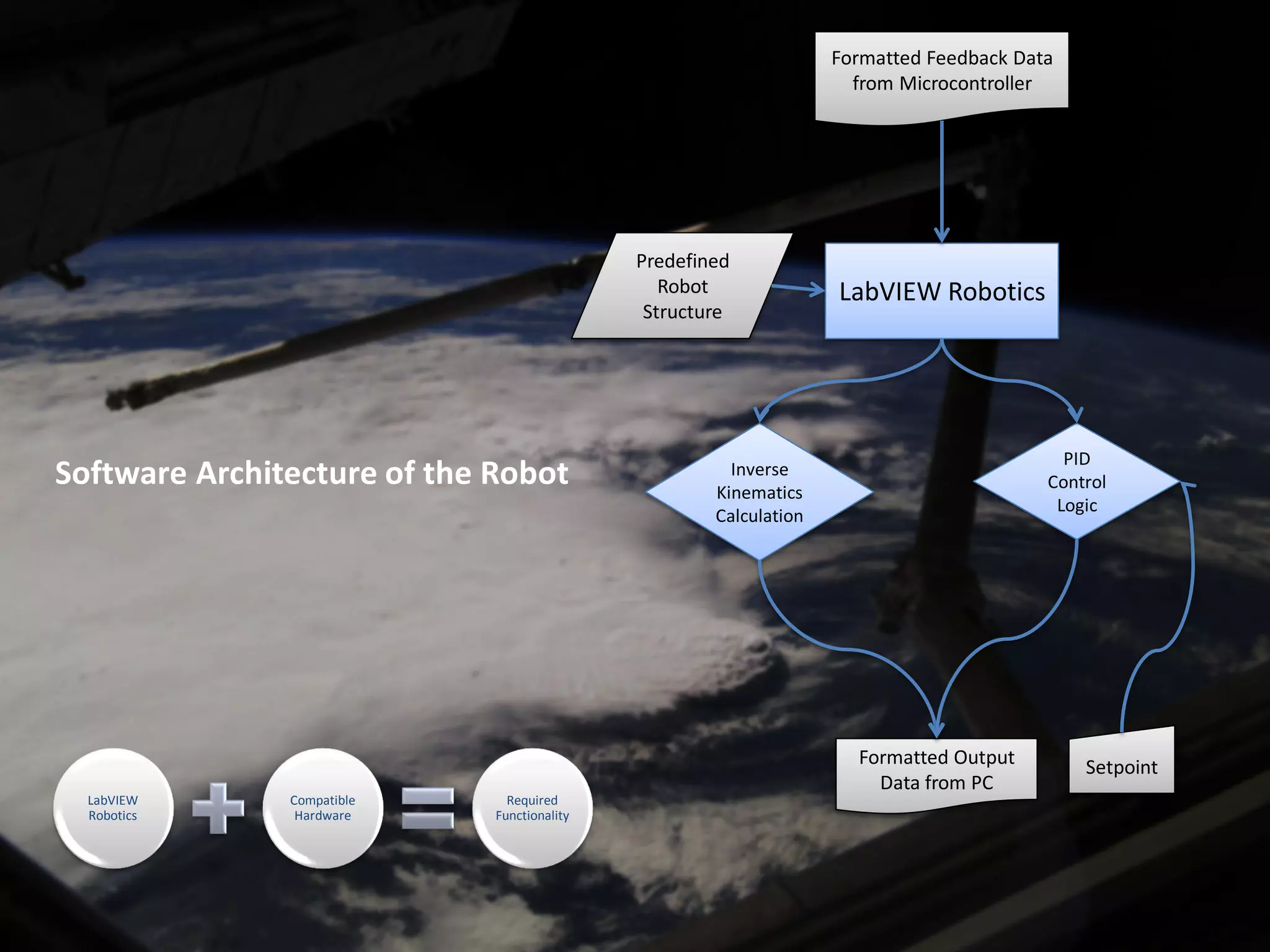
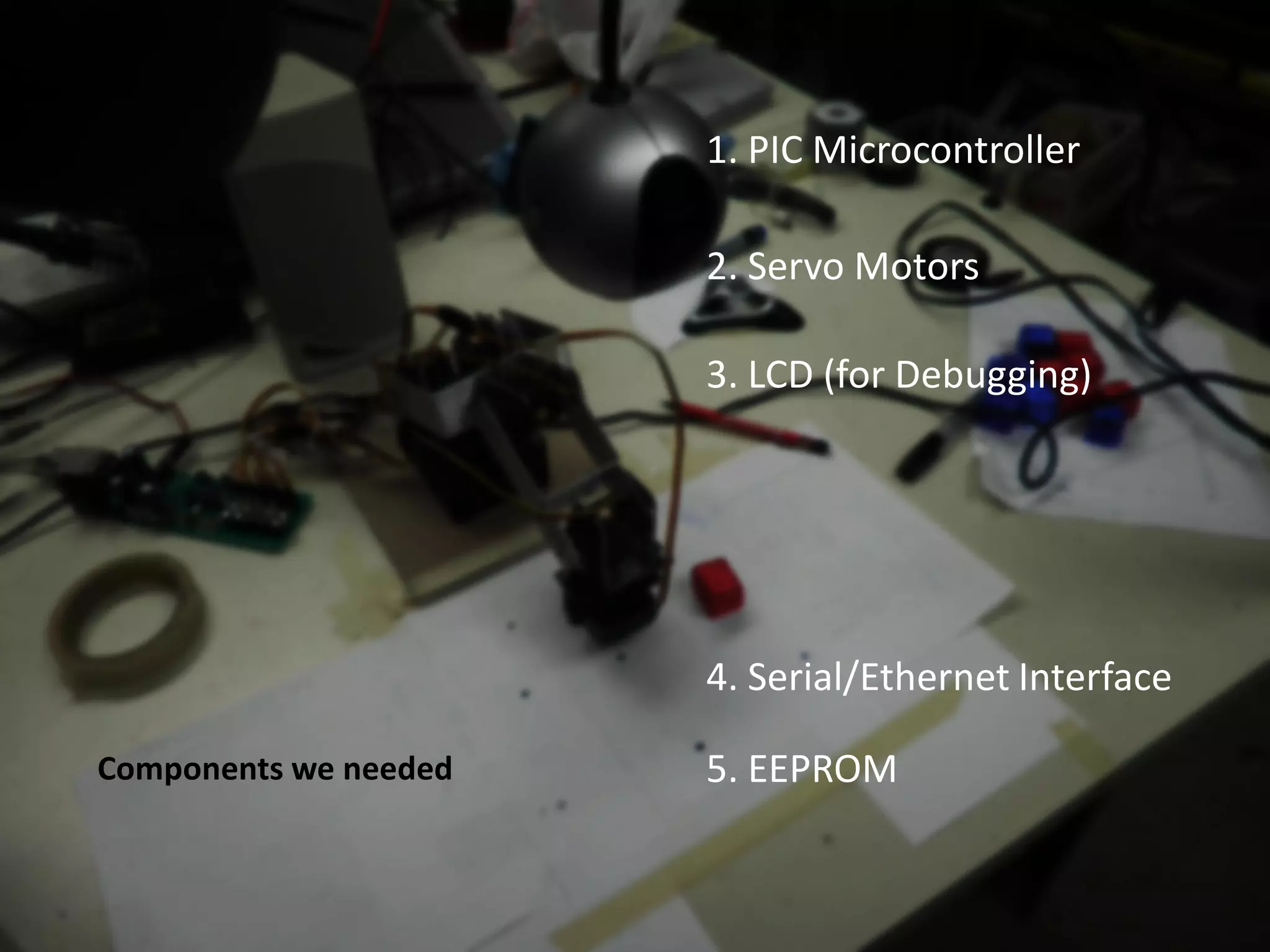
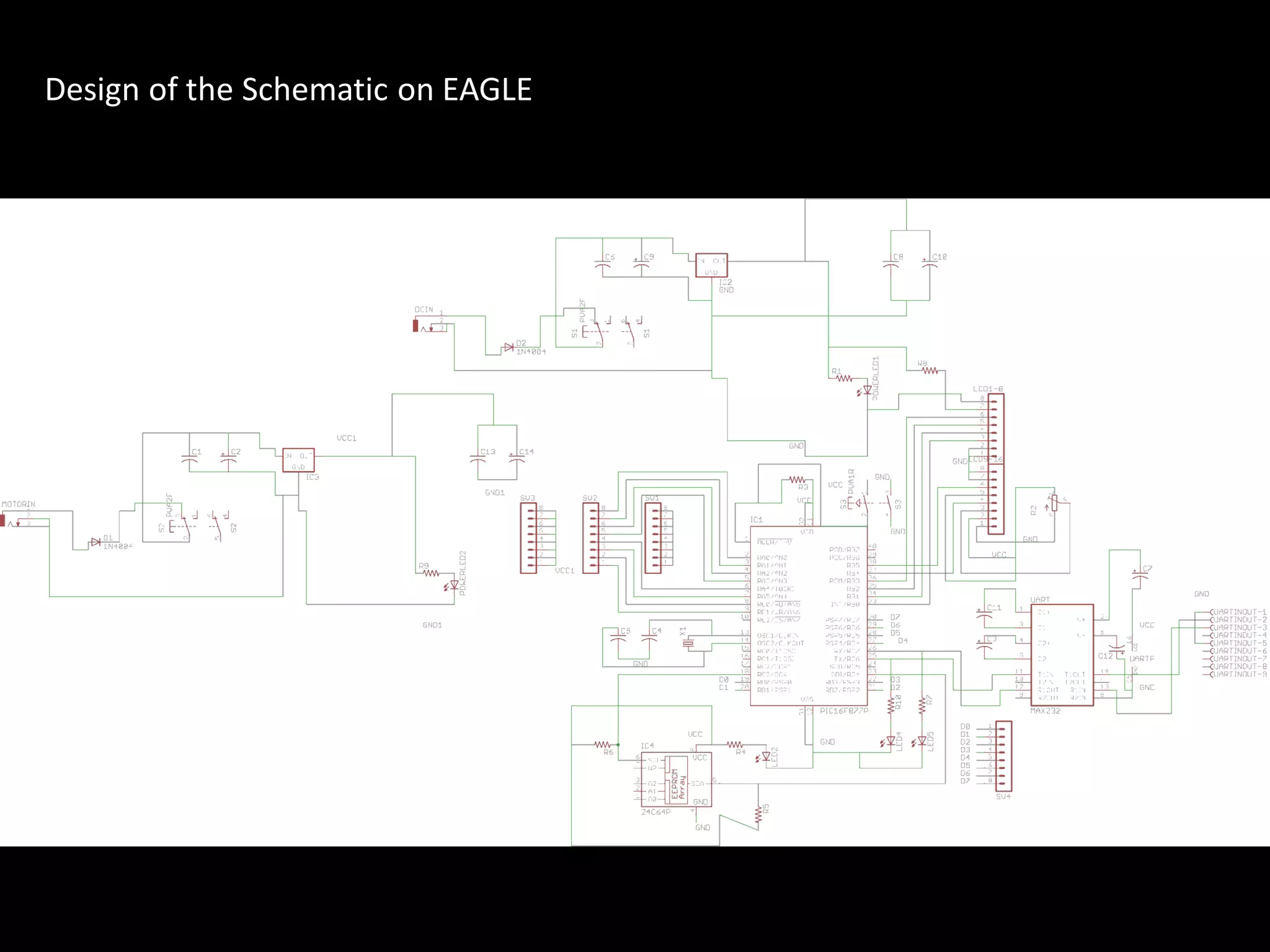
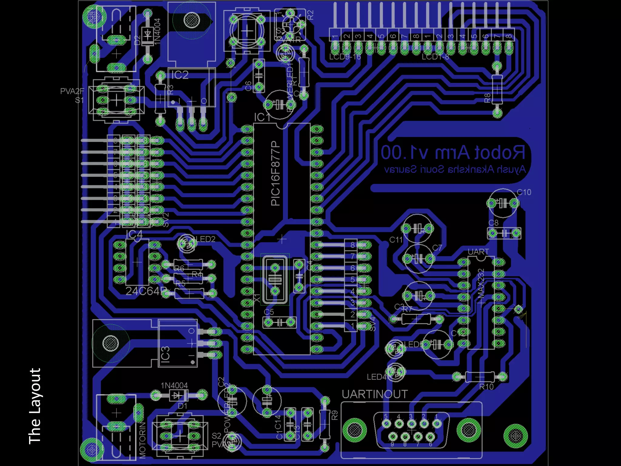
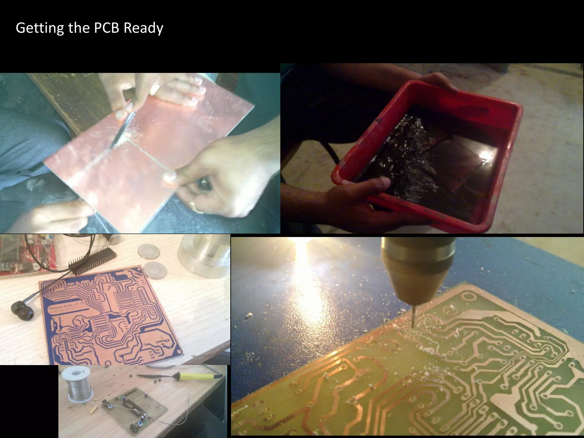
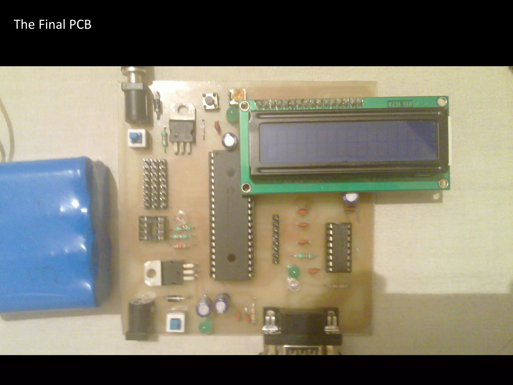
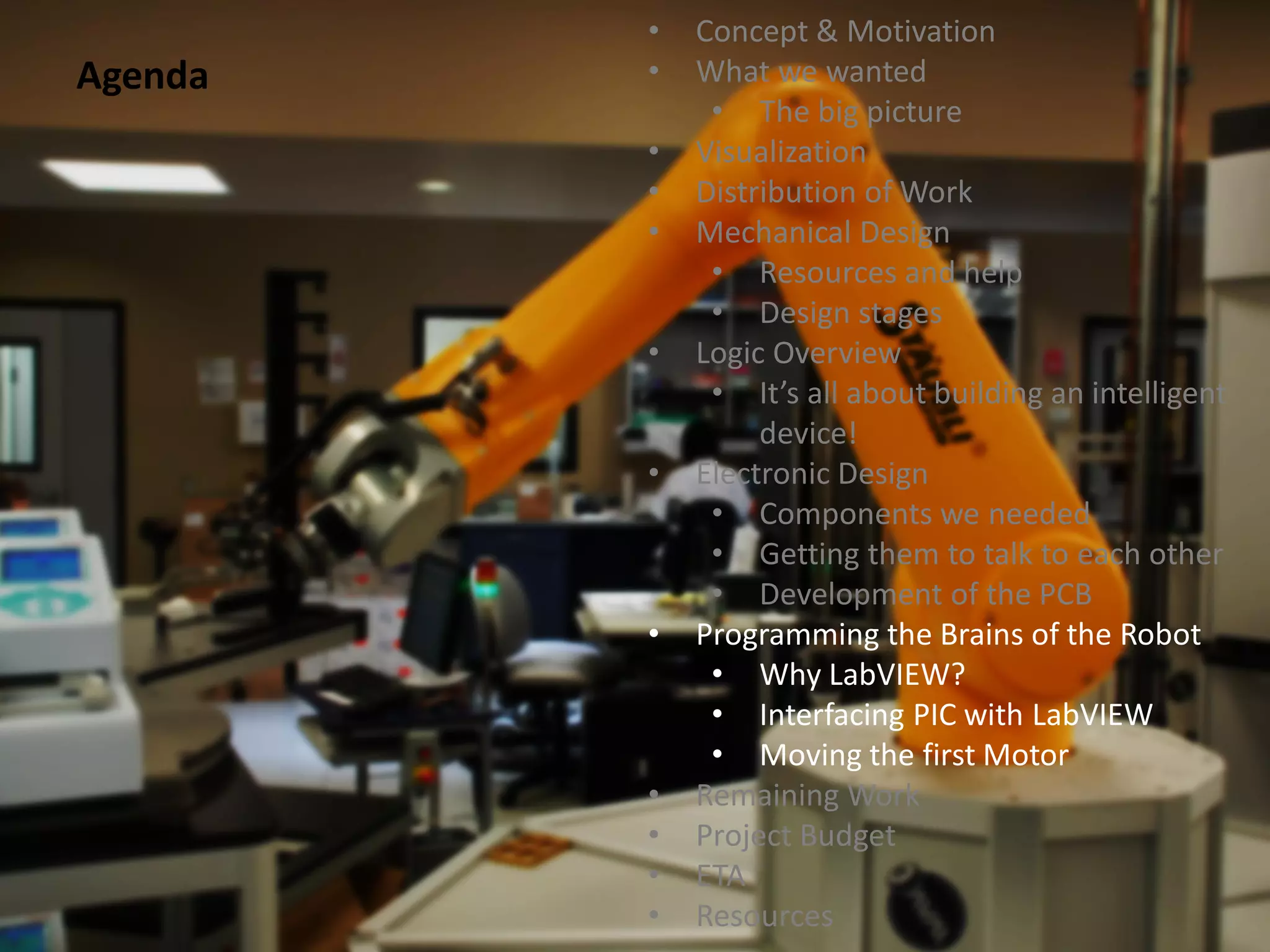
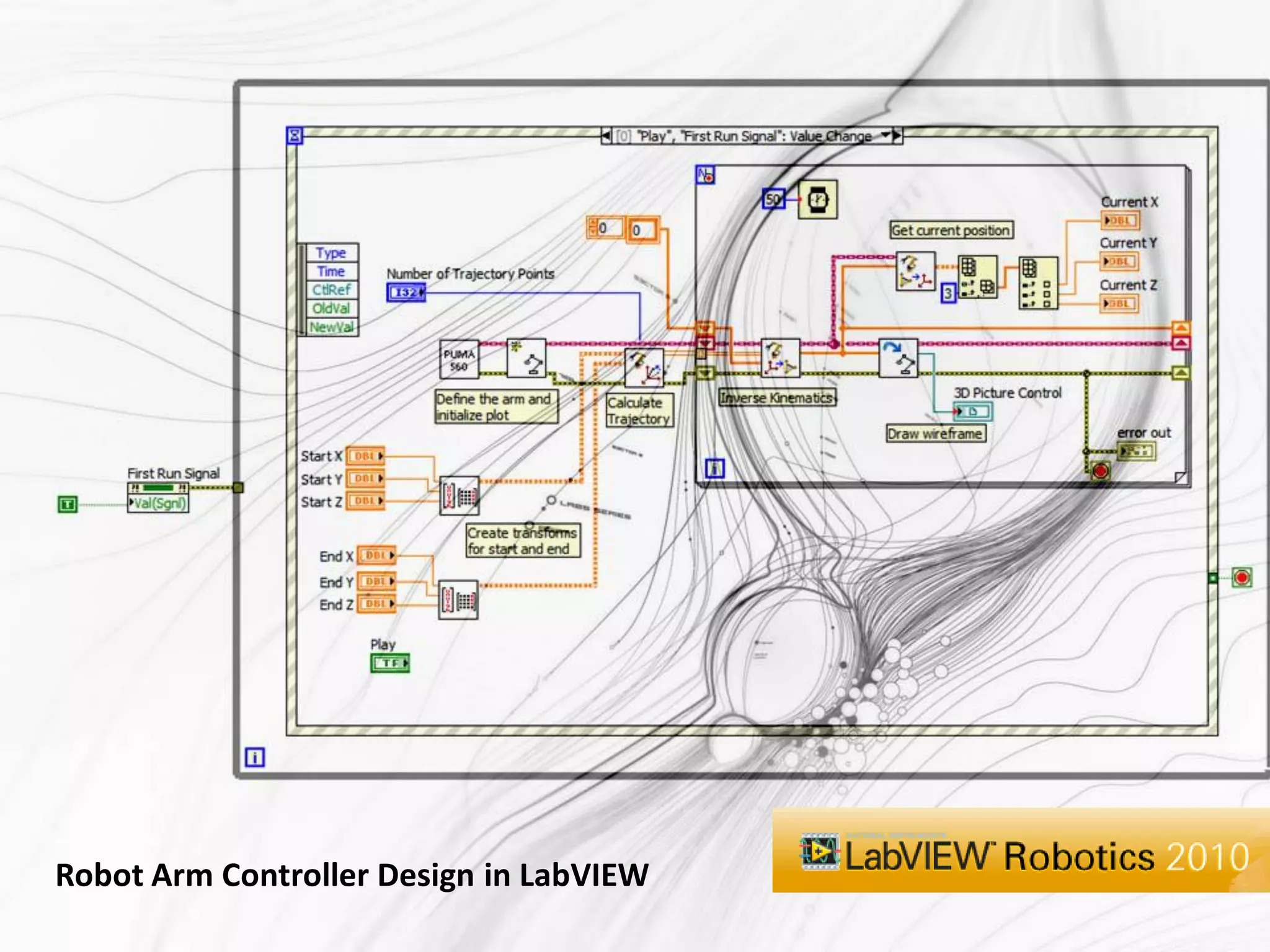
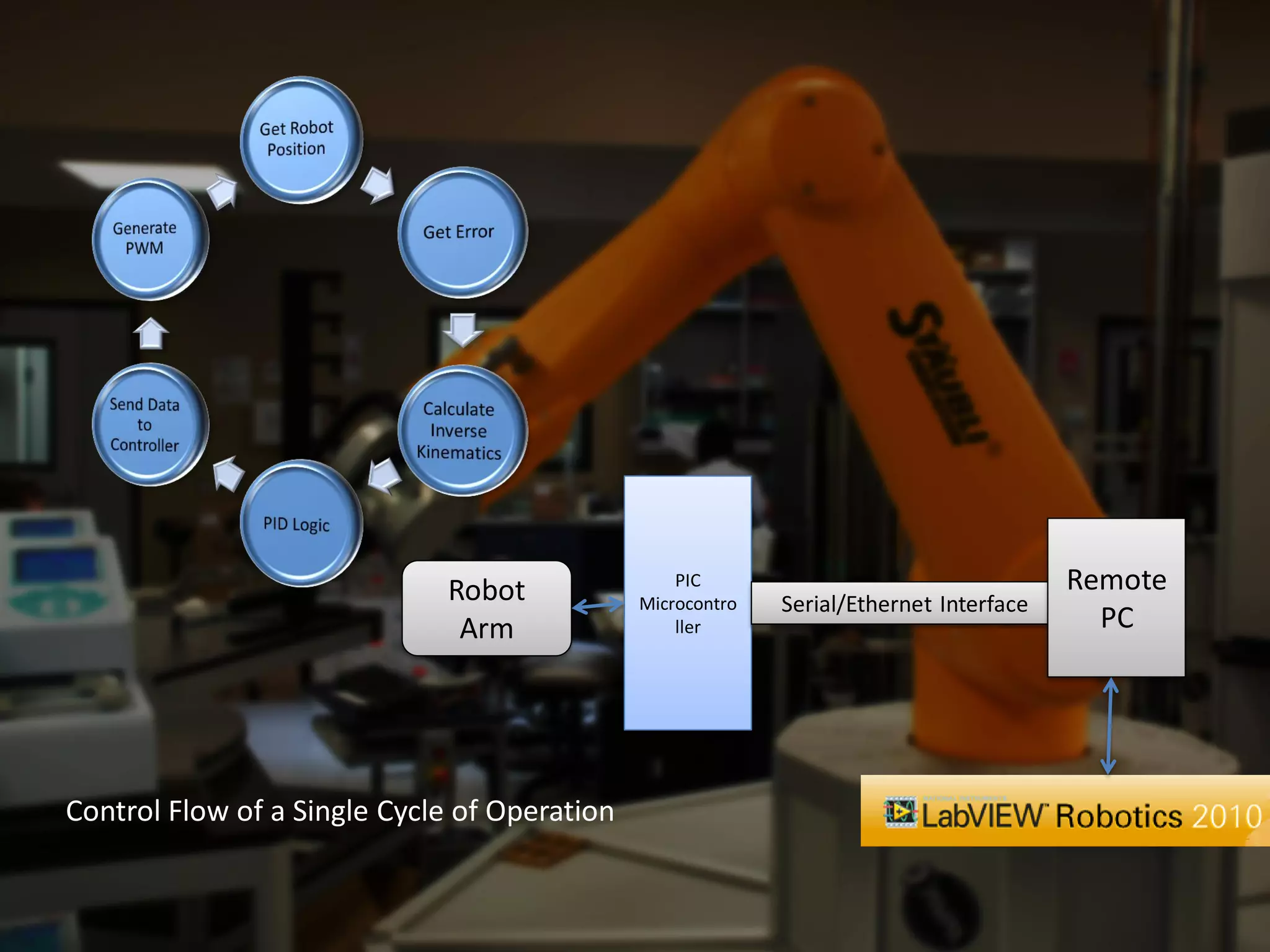
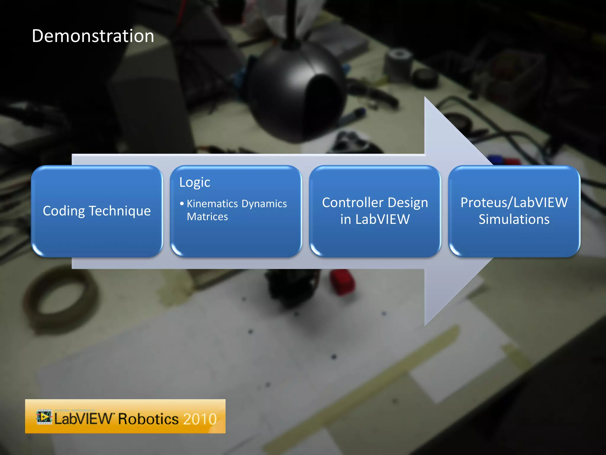
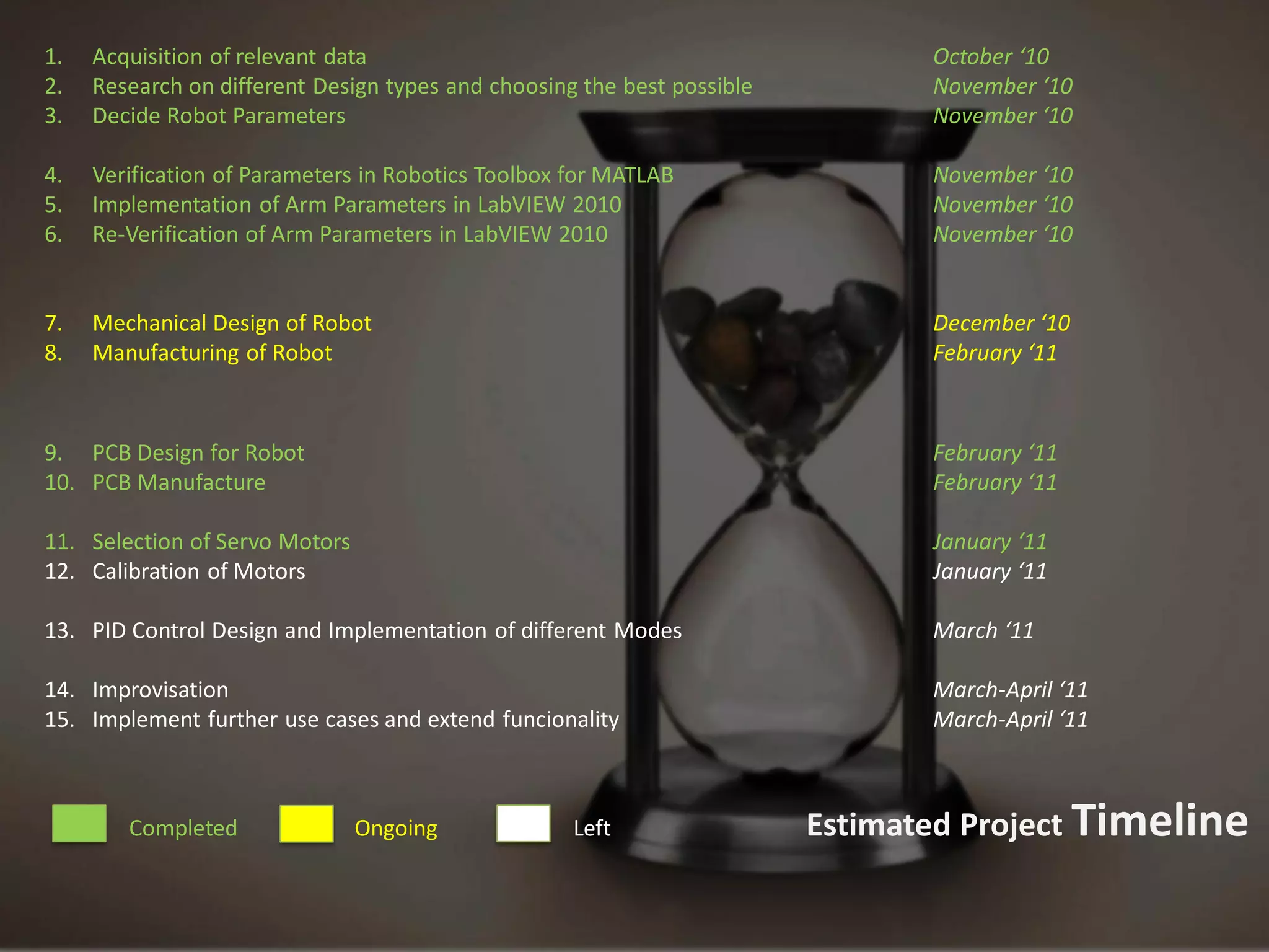
Development of a Five Axis Robot                  Arm implemented using
a PIC Microcontroller and LabVIEW Robotics 2010


                                             Akanksha Bahuguna
                                             Ayush Dewan
                                             Saurav Gusain
                                             Souri Guha
                                             Applied Electronics and Instrumentation
                                             2011 Batch
Our aim is to build a   4-axis Robot Arm

                The motion of the Arm will be controlled by a PIC
                Microcontroller that will communicate on a real
                time basis with LabVIEW which will do the
                calculations


Our Objective


                The basic function of the device will
                be to pick and place small objects
•   Concept & Motivation
Agenda   •   What we wanted
              • The big picture
         •   Visualization
         •   Distribution of Work
         •   Mechanical Design
              • Resources and help
              • Design stages
         •   Logic Overview
              • It’s all about building an intelligent
                  device!
         •   Electronic Design
              • Components we needed
              • Getting them to talk to each other
              • Development of the PCB
         •   Programming the Brains of the Robot
              • Why LabVIEW?
              • Interfacing PIC with LabVIEW
              • Moving the first Motor
         •   Remaining Work
         •   Project Budget
         •   ETA
         •   Resources
The design should be simple yet   High grade Accuracy and Speed
complex/stable enough for
Industrial Applications and for
R&D of various algorithms used
in Robotics
                                  Easy to modify


                                  Should be able serve the
                                  purpose of Educational
                                  Robotics


What we wanted when we            A prototype for a device that is
thought of building the Robot     ready to be used in Industry
Motivation
First Level Visualization
1.   Acquisition of relevant data                                               Akanksha, Ayush, Souri, Saurav
2.   Research on different Design types and choosing the best possible          Akanksha, Saurav
3.   Decide Robot Parameters                                                    Ayush

4.   Verification of Parameters in Robotics Toolbox for MATLAB                  Souri
5.   Simulation of all devices in PROTEUS                                       Ayush, Souri
6.   Implementation of Arm Parameters in LabVIEW 2010                           Ayush, Souri
7.   Re-Verification of Arm Parameters in LabVIEW 2010                          Saurav, Akanksha


8.   Mechanical Design of Robot                                                 Souri
9.   Manufacturing of Robot                                                     Saurav, Ayush

9. PCB Design for Robot                                                         Souri , Akanksha
10. PCB Manufacture                                                             Akanksha

11. Selection of Servo Motors                                                   Saurav
12. Calibration of Motors                                                       Souri

13. PID Control Design and Implementation of different Modes                    Souri, Ayush, Akanksha, Saurav

14. Improvisation                                                               Ayush, Souri, Akanksha, Saurav
15. Implement further use cases and extend funcionality                         Souri, Ayush


        Completed               Ongoing             Left                 Distributed Resposibilities
Initial Design

                      Revisions

                      Development of Parts


                      Assembly Design


Mechanical Design


                    Resource: MIT OpenCourseware Video Lectures
•   Concept & Motivation
Agenda   •   What we wanted
              • The big picture
         •   Visualization
         •   Distribution of Work
         •   Mechanical Design
              • Resources and help
              • Design stages
         •   Logic Overview
              • It’s all about building an intelligent
                  device!
         •   Electronic Design
              • Components we needed
              • Getting them to talk to each other
              • Development of the PCB
         •   Programming the Brains of the Robot
              • Why LabVIEW?
              • Interfacing PIC with LabVIEW
              • Moving the first Motor
         •   Remaining Work
         •   Project Budget
         •   ETA
         •   Resources
Servo 1

  Servo 2

  Servo 3       Multiple Quadrature
                     Encoders
                                      PIC Microcontroller

  Servo 4


                                              Ethernet/Serial Bus
  Servo 5


 Grip Servo


                                           Computer


Architecture of our Robot Arm
Formatted Feedback Data
                                                                     from Microcontroller


                                             Predefined
                                                Robot              LabVIEW Robotics
                                              Structure


                                                                                           PID
Software Architecture of the Robot                     Inverse
                                                     Kinematics
                                                                                         Control
                                                                                          Logic
                                                     Calculation


                                                                     Formatted Output        Setpoint
                                                                       Data from PC
  LabVIEW      Compatible      Required
  Robotics      Hardware     Functionality
Manipulation of the Robot Arm
•   Concept & Motivation
Agenda   •   What we wanted
              • The big picture
         •   Visualization
         •   Distribution of Work
         •   Mechanical Design
              • Resources and help
              • Design stages
         •   Logic Overview
              • It’s all about building an intelligent
                  device!
         •   Electronic Design
              • Components we needed
              • Getting them to talk to each other
              • Development of the PCB
         •   Programming the Brains of the Robot
              • Why LabVIEW?
              • Interfacing PIC with LabVIEW
              • Moving the first Motor
         •   Remaining Work
         •   Project Budget
         •   ETA
         •   Resources
1. PIC Microcontroller

                       2. Servo Motors

                       3. LCD (for Debugging)


                       4. Serial/Ethernet Interface

Components we needed   5. EEPROM
Design of the Schematic on EAGLE
The Layout
Generating the Layout in 3d – To prevent any misplaced component
Getting the PCB Ready
The Final PCB
•   Concept & Motivation
Agenda   •   What we wanted
              • The big picture
         •   Visualization
         •   Distribution of Work
         •   Mechanical Design
              • Resources and help
              • Design stages
         •   Logic Overview
              • It’s all about building an intelligent
                  device!
         •   Electronic Design
              • Components we needed
              • Getting them to talk to each other
              • Development of the PCB
         •   Programming the Brains of the Robot
              • Why LabVIEW?
              • Interfacing PIC with LabVIEW
              • Moving the first Motor
         •   Remaining Work
         •   Project Budget
         •   ETA
         •   Resources
Robot Arm Controller Design in LabVIEW
Robot                PIC                                   Remote
                                              Microcontro   Serial/Ethernet Interface
                              Arm                 ller                                    PC


Control Flow of a Single Cycle of Operation
Demonstration


                    Logic
                    • Kinematics Dynamics   Controller Design   Proteus/LabVIEW
 Coding Technique     Matrices                in LabVIEW           Simulations
1.   Acquisition of relevant data                                               October ‘10
2.   Research on different Design types and choosing the best possible          November ‘10
3.   Decide Robot Parameters                                                    November ‘10

4.   Verification of Parameters in Robotics Toolbox for MATLAB                  November ‘10
5.   Implementation of Arm Parameters in LabVIEW 2010                           November ‘10
6.   Re-Verification of Arm Parameters in LabVIEW 2010                          November ‘10


7.   Mechanical Design of Robot                                                 December ‘10
8.   Manufacturing of Robot                                                     February ‘11


9. PCB Design for Robot                                                         February ‘11
10. PCB Manufacture                                                             February ‘11

11. Selection of Servo Motors                                                   January ‘11
12. Calibration of Motors                                                       January ‘11

13. PID Control Design and Implementation of different Modes                    March ‘11

14. Improvisation                                                               March-April ‘11
15. Implement further use cases and extend funcionality                         March-April ‘11


        Completed               Ongoing             Left                 Estimated Project Timeline
thank   You!

A 4-Axis Robot Arm

  • 1.
    Development of aFive Axis Robot Arm implemented using a PIC Microcontroller and LabVIEW Robotics 2010 Akanksha Bahuguna Ayush Dewan Saurav Gusain Souri Guha Applied Electronics and Instrumentation 2011 Batch
  • 2.
    Our aim isto build a 4-axis Robot Arm The motion of the Arm will be controlled by a PIC Microcontroller that will communicate on a real time basis with LabVIEW which will do the calculations Our Objective The basic function of the device will be to pick and place small objects
  • 3.
    Concept & Motivation Agenda • What we wanted • The big picture • Visualization • Distribution of Work • Mechanical Design • Resources and help • Design stages • Logic Overview • It’s all about building an intelligent device! • Electronic Design • Components we needed • Getting them to talk to each other • Development of the PCB • Programming the Brains of the Robot • Why LabVIEW? • Interfacing PIC with LabVIEW • Moving the first Motor • Remaining Work • Project Budget • ETA • Resources
  • 4.
    The design shouldbe simple yet High grade Accuracy and Speed complex/stable enough for Industrial Applications and for R&D of various algorithms used in Robotics Easy to modify Should be able serve the purpose of Educational Robotics What we wanted when we A prototype for a device that is thought of building the Robot ready to be used in Industry
  • 5.
  • 6.
  • 8.
    1. Acquisition of relevant data Akanksha, Ayush, Souri, Saurav 2. Research on different Design types and choosing the best possible Akanksha, Saurav 3. Decide Robot Parameters Ayush 4. Verification of Parameters in Robotics Toolbox for MATLAB Souri 5. Simulation of all devices in PROTEUS Ayush, Souri 6. Implementation of Arm Parameters in LabVIEW 2010 Ayush, Souri 7. Re-Verification of Arm Parameters in LabVIEW 2010 Saurav, Akanksha 8. Mechanical Design of Robot Souri 9. Manufacturing of Robot Saurav, Ayush 9. PCB Design for Robot Souri , Akanksha 10. PCB Manufacture Akanksha 11. Selection of Servo Motors Saurav 12. Calibration of Motors Souri 13. PID Control Design and Implementation of different Modes Souri, Ayush, Akanksha, Saurav 14. Improvisation Ayush, Souri, Akanksha, Saurav 15. Implement further use cases and extend funcionality Souri, Ayush Completed Ongoing Left Distributed Resposibilities
  • 9.
    Initial Design Revisions Development of Parts Assembly Design Mechanical Design Resource: MIT OpenCourseware Video Lectures
  • 19.
    Concept & Motivation Agenda • What we wanted • The big picture • Visualization • Distribution of Work • Mechanical Design • Resources and help • Design stages • Logic Overview • It’s all about building an intelligent device! • Electronic Design • Components we needed • Getting them to talk to each other • Development of the PCB • Programming the Brains of the Robot • Why LabVIEW? • Interfacing PIC with LabVIEW • Moving the first Motor • Remaining Work • Project Budget • ETA • Resources
  • 20.
    Servo 1 Servo 2 Servo 3 Multiple Quadrature Encoders PIC Microcontroller Servo 4 Ethernet/Serial Bus Servo 5 Grip Servo Computer Architecture of our Robot Arm
  • 21.
    Formatted Feedback Data from Microcontroller Predefined Robot LabVIEW Robotics Structure PID Software Architecture of the Robot Inverse Kinematics Control Logic Calculation Formatted Output Setpoint Data from PC LabVIEW Compatible Required Robotics Hardware Functionality
  • 22.
  • 23.
    Concept & Motivation Agenda • What we wanted • The big picture • Visualization • Distribution of Work • Mechanical Design • Resources and help • Design stages • Logic Overview • It’s all about building an intelligent device! • Electronic Design • Components we needed • Getting them to talk to each other • Development of the PCB • Programming the Brains of the Robot • Why LabVIEW? • Interfacing PIC with LabVIEW • Moving the first Motor • Remaining Work • Project Budget • ETA • Resources
  • 24.
    1. PIC Microcontroller 2. Servo Motors 3. LCD (for Debugging) 4. Serial/Ethernet Interface Components we needed 5. EEPROM
  • 25.
    Design of theSchematic on EAGLE
  • 26.
  • 27.
    Generating the Layoutin 3d – To prevent any misplaced component
  • 28.
  • 29.
  • 30.
    Concept & Motivation Agenda • What we wanted • The big picture • Visualization • Distribution of Work • Mechanical Design • Resources and help • Design stages • Logic Overview • It’s all about building an intelligent device! • Electronic Design • Components we needed • Getting them to talk to each other • Development of the PCB • Programming the Brains of the Robot • Why LabVIEW? • Interfacing PIC with LabVIEW • Moving the first Motor • Remaining Work • Project Budget • ETA • Resources
  • 31.
    Robot Arm ControllerDesign in LabVIEW
  • 32.
    Robot PIC Remote Microcontro Serial/Ethernet Interface Arm ller PC Control Flow of a Single Cycle of Operation
  • 33.
    Demonstration Logic • Kinematics Dynamics Controller Design Proteus/LabVIEW Coding Technique Matrices in LabVIEW Simulations
  • 34.
    1. Acquisition of relevant data October ‘10 2. Research on different Design types and choosing the best possible November ‘10 3. Decide Robot Parameters November ‘10 4. Verification of Parameters in Robotics Toolbox for MATLAB November ‘10 5. Implementation of Arm Parameters in LabVIEW 2010 November ‘10 6. Re-Verification of Arm Parameters in LabVIEW 2010 November ‘10 7. Mechanical Design of Robot December ‘10 8. Manufacturing of Robot February ‘11 9. PCB Design for Robot February ‘11 10. PCB Manufacture February ‘11 11. Selection of Servo Motors January ‘11 12. Calibration of Motors January ‘11 13. PID Control Design and Implementation of different Modes March ‘11 14. Improvisation March-April ‘11 15. Implement further use cases and extend funcionality March-April ‘11 Completed Ongoing Left Estimated Project Timeline
  • 35.
    thank You!