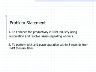
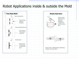
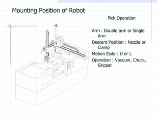
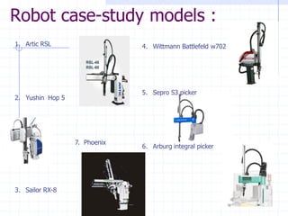
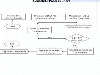
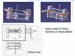
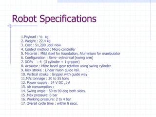
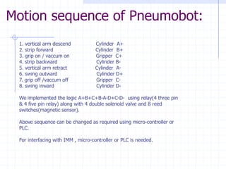
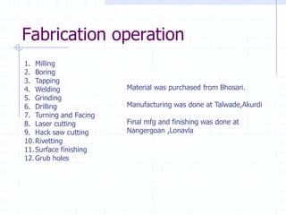
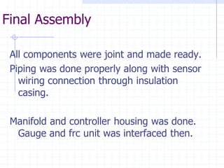
PneumobotSprue Picker Robot
Contents 
•Problem Statement 
•Plastic Injection moulding 
•Robotics 
•Automation 2012 visit & IATF 2013 
•Design and analysis 
•Pneumatics and electricals 
•Fabrication
Problem Statement1. To Enhance the productivity in IMM industry using automation and resolve issues regarding workers. 2. To perform pick and place operation within 8 seconds from IMM to Granulator.
Purpose of Project 
1.Consistency 
2.Fast Cycle time 
3.Less Labor Cost 
4.Product Hygiene 
5.Safety Issue 
6.2ndlevel Automation 
7.Continuous Operation 
8.Productivity
Abstract 
•Electro-pneumatic robot for automation in plastic IMM having mechanical gripper to remove sprue (waste component) from the mold and placing it into Granulator. 
•A linear and rotary pneumatic actuator will be used to give required motions. 
•Mitre Bevel gear to transmit power and torque. Linear nylon made slider for easy sliding motion 
.
Methodology 
1.Robot models and IMM study 
2.Exhibitions 
3.Industry survey 
4.Brain storming 
5.Pneumatics and Electricals. 
6.Design and material selection 
7.Analysis 
8.Design review and synthesis 
9.Fabrication 
10.Testing and results
Process flow in IMM :
Parts of Horizontal Injection moulding machine 
* 
Schematic of thermoplastic Injection molding machine
Arburg machine specifications : 
Clamp Tonnage / Machine 
Tie Bars ClearanceHxV(mm) 
Injection WeightPS. g (oz) 
Min -Max Mould Height. (mm) 
Opening Stroke Max (mm) 
25 Arburg 
221 
32 (1.13) 
150 -300 
200 
40 Kawaguchi 
275 x 245 
73 (2.57) 
150 -250 
230 
*55 Arburg 
320 x 320 
78 (2.5) 
min 225 
350 
*88 Arburg 
370 x 370 
89 (3.4) 
min 200 
450 
*110 Arburg 
420 x 420 
153 (5.9) 
min 250 
575 
125 Kawaguchi 
435 x 375 
226 (7.97) 
180 -400 
355 
140 Kawaguchi 
435 x 375 
260 (9.17) 
180 -400 
355 
175 Kawaguchi 
445 x 445 
372 (13.1) 
250 -450 
400 
*220 Sumitomo 
610 x 560 
532 (18.8) 
250 -580 
510 
265 Kawaguchi 
550 x 550 
649 (22.9) 
200 -550 
500 
*280 Sumitomo 
685 x 635 
733 (25.9) 
300 -620 
580 
300 Dongshin 
685 x 580 
970 (34.1) 
300 -680 
600
Component with sprue 
Component without sprue
Proposed designs 
1.Guide way cartesian model 
2.Articulated type (scara,revolute) 3. Cartesian type 
4.Swing arm type (vertical) 5. Swing arm type (horizontal)
Types of products :
Robot Applications inside & outside the Mold 
Two Plate Mold 
Sprue Picking Only 
Sprue and Parts RemovalPart RemovalSprue Picking with Part Dropping 
Sprue Picking with products connected 
Part removal with the sprue or without the sprue 
Simple OperationTaking out the Sprue from the mold and dropping it. ( Inside of the mold, Conveyor , Box ) 
Remove Parts, 90deg Rotation and Placing the parts ( Conveyor, Box)
Mounting Position of Robot 
Pick Operation 
Arm : Double arm or Single Arm 
Descent Position : Nozzle or Clamp 
Motion Style : U or L 
Operation : Vacuum, Chuck, Gripper
Robot case-study models : 
1.ArticRSL 
2.YushinHop 5 
3.Sailor RX-8 
4.Wittmann Battlefeld w702 
5.Sepro S3 picker 
6.Arburg integral picker 
7. Phoenix
Complete Process Chart Yes No Raw material (RM) for coloring and mixing Arrival of Raw materials & mould Mould on moulding machine using hoist RM feed to the Hopper Moulded components for finishing Sprue & defectives to granulator Component package and storage Dispatch of Component Start End Is product defective?
Catia model of Picker machine on fixed platten 
Drafted image
Cylinder selectionCylinder selection : Cylinder selection from Janatics Pneumatics catalogue through requirement of std stroke, bore and force. 3 A52 magentic cylinders and 1 A03 series male threaded cylinder for gripper. Dimensions and mechanisms of robot were finalized from cylinder selected. 
•Swing Cylinder Stroke 50mm ,Diameter 25mm 
•Kick Cylinder stroke 80mm ,Diameter 20mm 
•Vertical cylinder stroke 160mm ,diameter 16mm 
•Gripper cylinder stroke 20mm, diameter 16 mm.
Mechanisms 
1.Quarter turn pulley 
2.Power screw 
3.Electric motor 
4.Rack and pinion 
5.Pneumatic 4 piston actuator 
6.Spiral Bevel gear pair
Design considerations : 
We have used factor of safety of above 3 everywhere except in caseof gear we have fos = 2.4Our design is safe at 8 bar pressure. and gear pair fos is 1.2 at 8 bars. Solenoid valves can operate at max of 8 bar pressureAll other pneumatic component can sustain 10 bar pressure.
Design innovationsMitre bevel gear eliminated the need for wrist rotation of gripper plus reduced 1 movement of vertical cylinder. Arc bracket provides rotation on either side. Self made slider from nylon on Aluminium was made. Gripper was developed from compact cylinder.
Analytical design and analysisOur calculations predict that each cylinder can retract or extend in 0.2 seconds so we retrict ourself to max. of 4 to 6 bar pressure operation. As cycle is to be completed in 8 seconds, 4 bar pressure is sufficient. We designed Mitre bevel gear from Design data book taking cylinder specs into account. From gear pair , Shaft was designed. Bearing selection was done thenColumn was checked for buckling analysis. Swivel motion arc bracket was made. Cantilever beam analysis for carriage ,then Mountings plus sliding chuck was designed. Strong foundation design and guideways for vertical cylinder were provided at last.
Design of assembly in CATIAPart drawing was done in CATIA V5 and then assembly was done. Material was applied appropriately and CG ,weight ,MI were calculated then. Drafting was done for mfg drawings to workshops.
Material selection : 
1.Cast IronIt has good damping property and less density than steel but costly and not readilyavailable. Density= 7250 kg/m^3.2. Mild SteelIt has compartively less damping but good welding characteristics and cheap plus readily available. Density= 7850 kg/m^33. AluminiumLight weight with hardness and stiffness. Easy riveting possible. Density = 2710 kg/m^3 4. NylonFor easy sliding of carriage , nylon or teflon was considered.
Ansys analysis 
Critical components like horizontal shaft, arc bracket , base plate were examined for static and dynamic failure. 
Fos was safe for design made.
Pneumatic circuit concept 
1.Push button operated 
2.Interlocking circuit using limit switch operation 
3.Electro-pneumatic circuit using relays,reeds and solenoids. 
4.Micro-controller based. 
5.PLC based.
Pneumatic circuit working
Automation Studio 5.0Pure pneumatic circuit was made in this software but electro pneumatic circuit was just developed but not simulated. Fluidsim and autosim (SMC) softwares were tried out.
Electro-pneumatic circuit : 
The sensing time of reed switch is 1 millisecond. 
Reeds operate at 24 V DC 
Solenoid valves operate at 24 V DC with 104 mA current. 
As relay logic and logic gates could not be built , we choose controller. 
So A micro controller 8052 was used taking sensors as inputs (8) and solenoids as output (8) . Reset function was provided in case of sudden stops. 
C programming successfully implemented the required logic on controller.
Gripper 
1.Mechanical 2 finger gripper 
2.Vaccum gripper2 finger gripper had to be imported hence made a compact gripper from small double acting cylinder having one fixed jaw and other movable.
Habonim 4 piston actuator :
Robot Specifications 
1.Payload : ½ kg 
2. Weight : 22.4 kg 
3. Cost : 51,200 uptil now 
4. Control method : Micro controller 
5. Material : Mild steel for foundation, Aluminium for manipulator 
6. Configuration : Semi-cylindrical (swing arm) 
7. DOFs : 4 (3 cylinder + 1 gripper) 
8. Actuator : Mitre bevel gear rotation using swing cylinder 
9. Kick stroke : Linear nylon guide rail. 
10. Vertical stroke : Gripper with guide way 
11.M/c tonnage : 30 to 55 tons 
12. Power supply : 24 V DC ,1 A 
13. Air consumption : 
14. Swing angle : 50 to 90 deg both sides. 
15 .Max pressure: 6 bar 
16. Working pressure: 2 to 4 bar 
17. Overall cycle time : within 8 secs.
BOM 1 out of 4 bills 
Sr. no 
Model no. 
Specification /product 
Qty 
Cost 
Total 
1 
A52020080O 
DA 20 x 80 Cyl.(Mag) Basic 
1 
1243 
1243 
2 
A52025080O 
DA 25 x 50 Cyl.(Mag) Basic 
1 
1323 
1323 
3 
A52016160O 
DA 16 x 160 Cyl.(Mag) Basic 
1 
1176 
1176 
4 
DS254SS60-W 
1/8 -5/2,24V DC Double Sol. valve 
4 
2030 
8120 
5 
GR5105006 
Flow control valve 1/8 x Dia 6 
6 
224 
1344 
6 
WP2210650 
Male elbow Dia 6 x 1/8 
8 
43 
344 
7 
MS022 
DOUBLE FOOT MOUNTING (DIA 20,DIA 25) 
1 
234 
234 
8 
AA022 
CLEVIS FOOT BRACKET (DIA 20,DIA 25) 
1 
148 
148 
9 
AP010 
ROD END SPHERICAL EYE (DIA 25,DIA 32) 
2 
560 
1120 
10 
AP008 
ROD END SPHERICAL EYE (DIA 20) 
1 
511 
511 
11 
AM1016 
Reed switch with clamp (A52016) 
2 
451 
902 
12 
AM1020 
Reed switch with clamp (A52020) 
2 
451 
902 
13 
AM1025 
Reed switch with clamp (A52025) 
2 
451 
902 
14 
FRCLM146234/W 
FRCLM-3/8(40Micron,10bar)with Wall mounting brack 
1 
2649 
2649 
15 
WP2110851 
Male connector Dia8x 1/4 
2 
36 
72 
16 
M0030104 
Manifold (4 Valves) DS2-1/8,5/2,5/3 
1 
1355 
1355 
17 
ASC0161 
Silencer (Conical-1/4) 
2 
83 
166 
18 
WP2110852 
Male connector Dia8x3/8 
1 
41 
41 
19 
A2G02 
Pressure gauge(0-10bar)R1/8,Dia 40 
1 
171 
171 
20 
WH00B08 
TUBE(PU) OD8 (Blue) 
2 
56 
112 
21 
WH00B06 
TUBE(PU) OD6 (Blue) 
8 
31 
248 
22 
Parallel Gripper (10/ 16 dia) 
1 
0 
23 
Reed switch for parallel gripper 
2 
0 
24 
WC1 
Tube cutter 
1 
135 
135 
Total 
23218
Motion sequence of Pneumobot: 
1. vertical arm descend Cylinder A+ 
2. strip forward Cylinder B+ 
3. grip on / vaccum on Gripper C+ 
4. strip backwardCylinder B- 
5. vertical arm retract Cylinder A- 
6. swing outward Cylinder D+ 
7. grip off /vaccum offGripper C- 
8. swing inwardCylinder D- 
We implemented the logic A+B+C+B-A-D+C-D-using relay(4 three pin & 4 five pin relay) along with 4 double solenoid valve and 8 reed switches(magnetic sensor). 
Above sequence can be changed as required using micro-controller or PLC. 
For interfacing with IMM , micro-controller or PLC is needed.
1.Milling 
2.Boring 
3.Tapping 
4.Welding 
5.Grinding 
6.Drilling 
7.Turning and Facing 
8.Laser cutting 
9.Hack saw cutting 
10.Rivetting 
11.Surface finishing 
12.Grub holes 
Fabrication operationMaterial was purchased from Bhosari. Manufacturing was done at Talwade,AkurdiFinal mfg and finishing was done at Nangergoan ,Lonavla
Final Assembly 
All components were joint and made ready. 
Piping was done properly along with sensor wiring connection through insulation casing. 
Manifold and controller housing was done. Gauge and frc unit was interfaced then.
Thank You

Pneumobot-Pneumatic Pick and Place Robot

  • 1.
  • 2.
    Contents •Problem Statement •Plastic Injection moulding •Robotics •Automation 2012 visit & IATF 2013 •Design and analysis •Pneumatics and electricals •Fabrication
  • 3.
    Problem Statement1. ToEnhance the productivity in IMM industry using automation and resolve issues regarding workers. 2. To perform pick and place operation within 8 seconds from IMM to Granulator.
  • 4.
    Purpose of Project 1.Consistency 2.Fast Cycle time 3.Less Labor Cost 4.Product Hygiene 5.Safety Issue 6.2ndlevel Automation 7.Continuous Operation 8.Productivity
  • 5.
    Abstract •Electro-pneumatic robotfor automation in plastic IMM having mechanical gripper to remove sprue (waste component) from the mold and placing it into Granulator. •A linear and rotary pneumatic actuator will be used to give required motions. •Mitre Bevel gear to transmit power and torque. Linear nylon made slider for easy sliding motion .
  • 6.
    Methodology 1.Robot modelsand IMM study 2.Exhibitions 3.Industry survey 4.Brain storming 5.Pneumatics and Electricals. 6.Design and material selection 7.Analysis 8.Design review and synthesis 9.Fabrication 10.Testing and results
  • 7.
  • 8.
    Parts of HorizontalInjection moulding machine * Schematic of thermoplastic Injection molding machine
  • 9.
    Arburg machine specifications: Clamp Tonnage / Machine Tie Bars ClearanceHxV(mm) Injection WeightPS. g (oz) Min -Max Mould Height. (mm) Opening Stroke Max (mm) 25 Arburg 221 32 (1.13) 150 -300 200 40 Kawaguchi 275 x 245 73 (2.57) 150 -250 230 *55 Arburg 320 x 320 78 (2.5) min 225 350 *88 Arburg 370 x 370 89 (3.4) min 200 450 *110 Arburg 420 x 420 153 (5.9) min 250 575 125 Kawaguchi 435 x 375 226 (7.97) 180 -400 355 140 Kawaguchi 435 x 375 260 (9.17) 180 -400 355 175 Kawaguchi 445 x 445 372 (13.1) 250 -450 400 *220 Sumitomo 610 x 560 532 (18.8) 250 -580 510 265 Kawaguchi 550 x 550 649 (22.9) 200 -550 500 *280 Sumitomo 685 x 635 733 (25.9) 300 -620 580 300 Dongshin 685 x 580 970 (34.1) 300 -680 600
  • 10.
    Component with sprue Component without sprue
  • 11.
    Proposed designs 1.Guideway cartesian model 2.Articulated type (scara,revolute) 3. Cartesian type 4.Swing arm type (vertical) 5. Swing arm type (horizontal)
  • 12.
  • 13.
    Robot Applications inside& outside the Mold Two Plate Mold Sprue Picking Only Sprue and Parts RemovalPart RemovalSprue Picking with Part Dropping Sprue Picking with products connected Part removal with the sprue or without the sprue Simple OperationTaking out the Sprue from the mold and dropping it. ( Inside of the mold, Conveyor , Box ) Remove Parts, 90deg Rotation and Placing the parts ( Conveyor, Box)
  • 14.
    Mounting Position ofRobot Pick Operation Arm : Double arm or Single Arm Descent Position : Nozzle or Clamp Motion Style : U or L Operation : Vacuum, Chuck, Gripper
  • 15.
    Robot case-study models: 1.ArticRSL 2.YushinHop 5 3.Sailor RX-8 4.Wittmann Battlefeld w702 5.Sepro S3 picker 6.Arburg integral picker 7. Phoenix
  • 16.
    Complete Process ChartYes No Raw material (RM) for coloring and mixing Arrival of Raw materials & mould Mould on moulding machine using hoist RM feed to the Hopper Moulded components for finishing Sprue & defectives to granulator Component package and storage Dispatch of Component Start End Is product defective?
  • 17.
    Catia model ofPicker machine on fixed platten Drafted image
  • 18.
    Cylinder selectionCylinder selection: Cylinder selection from Janatics Pneumatics catalogue through requirement of std stroke, bore and force. 3 A52 magentic cylinders and 1 A03 series male threaded cylinder for gripper. Dimensions and mechanisms of robot were finalized from cylinder selected. •Swing Cylinder Stroke 50mm ,Diameter 25mm •Kick Cylinder stroke 80mm ,Diameter 20mm •Vertical cylinder stroke 160mm ,diameter 16mm •Gripper cylinder stroke 20mm, diameter 16 mm.
  • 19.
    Mechanisms 1.Quarter turnpulley 2.Power screw 3.Electric motor 4.Rack and pinion 5.Pneumatic 4 piston actuator 6.Spiral Bevel gear pair
  • 20.
    Design considerations : We have used factor of safety of above 3 everywhere except in caseof gear we have fos = 2.4Our design is safe at 8 bar pressure. and gear pair fos is 1.2 at 8 bars. Solenoid valves can operate at max of 8 bar pressureAll other pneumatic component can sustain 10 bar pressure.
  • 21.
    Design innovationsMitre bevelgear eliminated the need for wrist rotation of gripper plus reduced 1 movement of vertical cylinder. Arc bracket provides rotation on either side. Self made slider from nylon on Aluminium was made. Gripper was developed from compact cylinder.
  • 22.
    Analytical design andanalysisOur calculations predict that each cylinder can retract or extend in 0.2 seconds so we retrict ourself to max. of 4 to 6 bar pressure operation. As cycle is to be completed in 8 seconds, 4 bar pressure is sufficient. We designed Mitre bevel gear from Design data book taking cylinder specs into account. From gear pair , Shaft was designed. Bearing selection was done thenColumn was checked for buckling analysis. Swivel motion arc bracket was made. Cantilever beam analysis for carriage ,then Mountings plus sliding chuck was designed. Strong foundation design and guideways for vertical cylinder were provided at last.
  • 23.
    Design of assemblyin CATIAPart drawing was done in CATIA V5 and then assembly was done. Material was applied appropriately and CG ,weight ,MI were calculated then. Drafting was done for mfg drawings to workshops.
  • 24.
    Material selection : 1.Cast IronIt has good damping property and less density than steel but costly and not readilyavailable. Density= 7250 kg/m^3.2. Mild SteelIt has compartively less damping but good welding characteristics and cheap plus readily available. Density= 7850 kg/m^33. AluminiumLight weight with hardness and stiffness. Easy riveting possible. Density = 2710 kg/m^3 4. NylonFor easy sliding of carriage , nylon or teflon was considered.
  • 25.
    Ansys analysis Criticalcomponents like horizontal shaft, arc bracket , base plate were examined for static and dynamic failure. Fos was safe for design made.
  • 26.
    Pneumatic circuit concept 1.Push button operated 2.Interlocking circuit using limit switch operation 3.Electro-pneumatic circuit using relays,reeds and solenoids. 4.Micro-controller based. 5.PLC based.
  • 27.
  • 28.
    Automation Studio 5.0Purepneumatic circuit was made in this software but electro pneumatic circuit was just developed but not simulated. Fluidsim and autosim (SMC) softwares were tried out.
  • 29.
    Electro-pneumatic circuit : The sensing time of reed switch is 1 millisecond. Reeds operate at 24 V DC Solenoid valves operate at 24 V DC with 104 mA current. As relay logic and logic gates could not be built , we choose controller. So A micro controller 8052 was used taking sensors as inputs (8) and solenoids as output (8) . Reset function was provided in case of sudden stops. C programming successfully implemented the required logic on controller.
  • 30.
    Gripper 1.Mechanical 2finger gripper 2.Vaccum gripper2 finger gripper had to be imported hence made a compact gripper from small double acting cylinder having one fixed jaw and other movable.
  • 31.
    Habonim 4 pistonactuator :
  • 32.
    Robot Specifications 1.Payload: ½ kg 2. Weight : 22.4 kg 3. Cost : 51,200 uptil now 4. Control method : Micro controller 5. Material : Mild steel for foundation, Aluminium for manipulator 6. Configuration : Semi-cylindrical (swing arm) 7. DOFs : 4 (3 cylinder + 1 gripper) 8. Actuator : Mitre bevel gear rotation using swing cylinder 9. Kick stroke : Linear nylon guide rail. 10. Vertical stroke : Gripper with guide way 11.M/c tonnage : 30 to 55 tons 12. Power supply : 24 V DC ,1 A 13. Air consumption : 14. Swing angle : 50 to 90 deg both sides. 15 .Max pressure: 6 bar 16. Working pressure: 2 to 4 bar 17. Overall cycle time : within 8 secs.
  • 33.
    BOM 1 outof 4 bills Sr. no Model no. Specification /product Qty Cost Total 1 A52020080O DA 20 x 80 Cyl.(Mag) Basic 1 1243 1243 2 A52025080O DA 25 x 50 Cyl.(Mag) Basic 1 1323 1323 3 A52016160O DA 16 x 160 Cyl.(Mag) Basic 1 1176 1176 4 DS254SS60-W 1/8 -5/2,24V DC Double Sol. valve 4 2030 8120 5 GR5105006 Flow control valve 1/8 x Dia 6 6 224 1344 6 WP2210650 Male elbow Dia 6 x 1/8 8 43 344 7 MS022 DOUBLE FOOT MOUNTING (DIA 20,DIA 25) 1 234 234 8 AA022 CLEVIS FOOT BRACKET (DIA 20,DIA 25) 1 148 148 9 AP010 ROD END SPHERICAL EYE (DIA 25,DIA 32) 2 560 1120 10 AP008 ROD END SPHERICAL EYE (DIA 20) 1 511 511 11 AM1016 Reed switch with clamp (A52016) 2 451 902 12 AM1020 Reed switch with clamp (A52020) 2 451 902 13 AM1025 Reed switch with clamp (A52025) 2 451 902 14 FRCLM146234/W FRCLM-3/8(40Micron,10bar)with Wall mounting brack 1 2649 2649 15 WP2110851 Male connector Dia8x 1/4 2 36 72 16 M0030104 Manifold (4 Valves) DS2-1/8,5/2,5/3 1 1355 1355 17 ASC0161 Silencer (Conical-1/4) 2 83 166 18 WP2110852 Male connector Dia8x3/8 1 41 41 19 A2G02 Pressure gauge(0-10bar)R1/8,Dia 40 1 171 171 20 WH00B08 TUBE(PU) OD8 (Blue) 2 56 112 21 WH00B06 TUBE(PU) OD6 (Blue) 8 31 248 22 Parallel Gripper (10/ 16 dia) 1 0 23 Reed switch for parallel gripper 2 0 24 WC1 Tube cutter 1 135 135 Total 23218
  • 34.
    Motion sequence ofPneumobot: 1. vertical arm descend Cylinder A+ 2. strip forward Cylinder B+ 3. grip on / vaccum on Gripper C+ 4. strip backwardCylinder B- 5. vertical arm retract Cylinder A- 6. swing outward Cylinder D+ 7. grip off /vaccum offGripper C- 8. swing inwardCylinder D- We implemented the logic A+B+C+B-A-D+C-D-using relay(4 three pin & 4 five pin relay) along with 4 double solenoid valve and 8 reed switches(magnetic sensor). Above sequence can be changed as required using micro-controller or PLC. For interfacing with IMM , micro-controller or PLC is needed.
  • 35.
    1.Milling 2.Boring 3.Tapping 4.Welding 5.Grinding 6.Drilling 7.Turning and Facing 8.Laser cutting 9.Hack saw cutting 10.Rivetting 11.Surface finishing 12.Grub holes Fabrication operationMaterial was purchased from Bhosari. Manufacturing was done at Talwade,AkurdiFinal mfg and finishing was done at Nangergoan ,Lonavla
  • 36.
    Final Assembly Allcomponents were joint and made ready. Piping was done properly along with sensor wiring connection through insulation casing. Manifold and controller housing was done. Gauge and frc unit was interfaced then.
  • 37.